
Hardware Installation Guide
Page 3
... 10 100BASE-FX Ports 12 SFP Module Slots 12 SFP Modules 13 XENPAK Module Slot (Catalyst 3750G-16TD Switch) 13 LEDs 13 System LED 15 RPS LED 16 Master LED 16 Port LEDs and Modes 17 Rear Panel Description 21 StackWise Ports 24 Power Connectors 25 Internal Power Supply Connector 25 DC Power Connector 25 Cisco RPS Connector 25 Console...
... 10 100BASE-FX Ports 12 SFP Module Slots 12 SFP Modules 13 XENPAK Module Slot (Catalyst 3750G-16TD Switch) 13 LEDs 13 System LED 15 RPS LED 16 Master LED 16 Port LEDs and Modes 17 Rear Panel Description 21 StackWise Ports 24 Power Connectors 25 Internal Power Supply Connector 25 DC Power Connector 25 Cisco RPS Connector 25 Console...

Hardware Installation Guide
Page 13
... 1000 Mb/s. • The Catalyst 3750 switches support stacking. StackWise ports are not user-configurable. • Switches are numbered 1 (left) and 2 (right). The Catalyst 3750G-12S-SD switch does not support an RPS. You can configure duplex mode to half, full, or autonegotiate on AC input and supplies backup DC power output to the Catalyst 3750 switches. You cannot configure half...
... 1000 Mb/s. • The Catalyst 3750 switches support stacking. StackWise ports are not user-configurable. • Switches are numbered 1 (left) and 2 (right). The Catalyst 3750G-12S-SD switch does not support an RPS. You can configure duplex mode to half, full, or autonegotiate on AC input and supplies backup DC power output to the Catalyst 3750 switches. You cannot configure half...

Hardware Installation Guide
Page 26
... a standalone switch. Contact Cisco Systems. The internal power supply in a fault condition. Switch is off or not properly connected. An error occurred when the switch was selecting the stack master switch or a stack error. 1-16 Catalyst 3750 Switch Hardware Installation Guide OL-6336-10 RPS is not the stack master. Press the Standby/Active button on the Catalyst 3750G-12S-SD switch. These...
... a standalone switch. Contact Cisco Systems. The internal power supply in a fault condition. Switch is off or not properly connected. An error occurred when the switch was selecting the stack master switch or a stack error. 1-16 Catalyst 3750 Switch Hardware Installation Guide OL-6336-10 RPS is not the stack master. Press the Standby/Active button on the Catalyst 3750G-12S-SD switch. These...

Hardware Installation Guide
Page 35
... Rear Panel Description You can also connect the Cisco RPS 2300 or the Cisco RPS 675 to -72 VDC. Note The Catalyst 3750 switch and the redundant power systems should the switch internal power supply fail. DC Power Connector The Catalyst 3750G-12S-SD has an internal DC-power converter. It automatically senses if an internal power supply of 2300 W. It has dual feeds (A and...
... Rear Panel Description You can also connect the Cisco RPS 2300 or the Cisco RPS 675 to -72 VDC. Note The Catalyst 3750 switch and the redundant power systems should the switch internal power supply fail. DC Power Connector The Catalyst 3750G-12S-SD has an internal DC-power converter. It automatically senses if an internal power supply of 2300 W. It has dual feeds (A and...
Hardware Installation Guide
Page 36
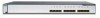
... V and 12 V with Cisco Network Assistant guide on Cisco.com. • Device manager You can use web interface that adapter from Cisco. It automatically senses when the internal power supply of a connected device fails and provides power to -DB-25 female DTE adapter. Console Port You can configure and manage switch clusters or standalone switches. Note On the Catalyst 3750G-24WS...
... V and 12 V with Cisco Network Assistant guide on Cisco.com. • Device manager You can use web interface that adapter from Cisco. It automatically senses when the internal power supply of a connected device fails and provides power to -DB-25 female DTE adapter. Console Port You can configure and manage switch clusters or standalone switches. Note On the Catalyst 3750G-24WS...

Hardware Installation Guide
Page 42
..., the following ports must be allowed to all times, because it in the absence of : 45•C Statement 1047 Catalyst 3750 Switch Hardware Installation Guide 2-4 OL-6336-10 Statement 1046 Warning To prevent the system from overheating, do not operate it serves ...of this product should be accessible at all national laws and regulations. Statement 1024 Warning This unit might have more than one power supply connection. Statement 1030 Warning Ultimate disposal of security. Statement 1019 Warning A readily accessible two-poled disconnect device must be handled according...
..., the following ports must be allowed to all times, because it in the absence of : 45•C Statement 1047 Catalyst 3750 Switch Hardware Installation Guide 2-4 OL-6336-10 Statement 1046 Warning To prevent the system from overheating, do not operate it serves ...of this product should be accessible at all national laws and regulations. Statement 1024 Warning This unit might have more than one power supply connection. Statement 1030 Warning Ultimate disposal of security. Statement 1019 Warning A readily accessible two-poled disconnect device must be handled according...
Hardware Installation Guide
Page 45
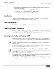
...RPS-N1=. Statement 370 As the switch powers on a DC switch, see the Cisco RPS documentation for the steps required to connect a PC to the switch and to an AC power outlet. OL-6336-10 Catalyst 3750 Switch Hardware Installation Guide 2-7 International Electrotechnical ...supply a number-2 Phillips screwdriver to the AC power connector on the switch and verify that the switch functions properly. Verifying Switch Operation Before you install the switch in standby mode when you should power on the switch, and connect the other LEDs remain continuous green. To power on the switch...
...RPS-N1=. Statement 370 As the switch powers on a DC switch, see the Cisco RPS documentation for the steps required to connect a PC to the switch and to an AC power outlet. OL-6336-10 Catalyst 3750 Switch Hardware Installation Guide 2-7 International Electrotechnical ...supply a number-2 Phillips screwdriver to the AC power connector on the switch and verify that the switch functions properly. Verifying Switch Operation Before you install the switch in standby mode when you should power on the switch, and connect the other LEDs remain continuous green. To power on the switch...

Hardware Installation Guide
Page 46
... the rack if you plan to the rear of the StackWise cable, the 0.5-meter cable is supplied. For switch dimensions, see the "StackWise Ports" section on a shelf as described in which you can order it easier to cable the... Catalyst 3750 Switch Hardware Installation Guide 2-8 OL-6336-10 The other switches. If you plan to manage switch stacks, see the switch software configuration guide. Powering Considerations Consider the following guidelines before you might affect the switch that becomes the stack master. Call Cisco Systems if your Cisco supplier. Powering Off the Switch ...
... the rack if you plan to the rear of the StackWise cable, the 0.5-meter cable is supplied. For switch dimensions, see the "StackWise Ports" section on a shelf as described in which you can order it easier to cable the... Catalyst 3750 Switch Hardware Installation Guide 2-8 OL-6336-10 The other switches. If you plan to manage switch stacks, see the switch software configuration guide. Powering Considerations Consider the following guidelines before you might affect the switch that becomes the stack master. Call Cisco Systems if your Cisco supplier. Powering Off the Switch ...

Hardware Installation Guide
Page 67
... 12X 11X 10 11 12 1X 2X 8 9 67 45 23 1 MODE STASCPKEDEUDPSLTXAMTASRTPRSSYST 1 1 86570 1 User-supplied screws After the switch is attached securely to wall studs or to a firmly attached plywood-mounting backboard. Chapter 2 Switch Installation Installing the Switch Mounting the Switch on page 2-7. See the Catalyst 3750 Switch Getting Started Guide for information on powering considerations. • Connect to...
... 12X 11X 10 11 12 1X 2X 8 9 67 45 23 1 MODE STASCPKEDEUDPSLTXAMTASRTPRSSYST 1 1 86570 1 User-supplied screws After the switch is attached securely to wall studs or to a firmly attached plywood-mounting backboard. Chapter 2 Switch Installation Installing the Switch Mounting the Switch on page 2-7. See the Catalyst 3750 Switch Getting Started Guide for information on powering considerations. • Connect to...

Hardware Installation Guide
Page 87
...Diagnosing Problems • For copper connections, determine if a crossover cable was required or the reverse. See Table 1-5 on page 1-12 for a description of supported SFP modules. Only standard-compliant cabling can cause one shutdown port can be seated, but the other... type. OL-6336-10 Catalyst 3750 Switch Hardware Installation Guide 3-3 Replace the crossover cable with a known, good module. See Appendix B, "Cable and Adapter Specifications," for Cisco to identify and validate that the power supply installed in the switch meets the power requirements of the cable are...
...Diagnosing Problems • For copper connections, determine if a crossover cable was required or the reverse. See Table 1-5 on page 1-12 for a description of supported SFP modules. Only standard-compliant cabling can cause one shutdown port can be seated, but the other... type. OL-6336-10 Catalyst 3750 Switch Hardware Installation Guide 3-3 Replace the crossover cable with a known, good module. See Appendix B, "Cable and Adapter Specifications," for Cisco to identify and validate that the power supply installed in the switch meets the power requirements of the cable are...

Hardware Installation Guide
Page 122
...must connect the Catalyst 3750G-12S-SD switch only to a DC-input power source that power is removed from -36 to -72 VDC. Caution The switch must comply with 5 A-branch-circuit protection. Figure C-4 Terminal Block Plug 60530 Catalyst 3750 Switch Hardware Installation ...Guide C-4 OL-6336-10 Step 2 Locate and remove the terminal block plug (see Figure C-4). Connecting to DC Power Appendix C Connecting to DC Power Wiring the DC-Input Power Source Warning Before performing any of the following procedures, ensure that has an input supply...
...must connect the Catalyst 3750G-12S-SD switch only to a DC-input power source that power is removed from -36 to -72 VDC. Caution The switch must comply with 5 A-branch-circuit protection. Figure C-4 Terminal Block Plug 60530 Catalyst 3750 Switch Hardware Installation ...Guide C-4 OL-6336-10 Step 2 Locate and remove the terminal block plug (see Figure C-4). Connecting to DC Power Appendix C Connecting to DC Power Wiring the DC-Input Power Source Warning Before performing any of the following procedures, ensure that has an input supply...

Hardware Installation Guide
Page 129
...Catalyst 3750 SERIES 2 3 90533 4 1 Catalyst 3750 switch 3 AC power cord 2 RJ-45-to-DB-9 adapter cable 4 StackWise cable (optional) Note For a DC switch, you can use either a crossover or a straight-through cables to connect the switch ports to other end of device on switches running Cisco IOS Release 12.2(18)SE or later. Therefore, you will have a DC power supply... terminal block. The auto-MDIX feature is enabled, the switch detects ...
...Catalyst 3750 SERIES 2 3 90533 4 1 Catalyst 3750 switch 3 AC power cord 2 RJ-45-to-DB-9 adapter cable 4 StackWise cable (optional) Note For a DC switch, you can use either a crossover or a straight-through cables to connect the switch ports to other end of device on switches running Cisco IOS Release 12.2(18)SE or later. Therefore, you will have a DC power supply... terminal block. The auto-MDIX feature is enabled, the switch detects ...

Hardware Installation Guide
Page 131
[email protected] [email protected] 1 2 90531 1 Catalyst 3750 switches 2 Power cord 3 RJ-45-to the console port of one of the switches in Figure D-4. Attach the DB-9 female DTE of a switch, as shown in the stack. The initial configuration for the ...entire stack can use the supplied RJ-45-to perform the initial configuration. Note If you have stacked your switches, connect to -DB-9 adapter cable OL-6336-09 Catalyst 3750 Switch Hardware Installation Guide D-5 To connect the switch console port to a PC, use ...
[email protected] [email protected] 1 2 90531 1 Catalyst 3750 switches 2 Power cord 3 RJ-45-to the console port of one of the switches in Figure D-4. Attach the DB-9 female DTE of a switch, as shown in the stack. The initial configuration for the ...entire stack can use the supplied RJ-45-to perform the initial configuration. Note If you have stacked your switches, connect to -DB-9 adapter cable OL-6336-09 Catalyst 3750 Switch Hardware Installation Guide D-5 To connect the switch console port to a PC, use ...

Hardware Installation Guide
Page 132
... ProcommPlus-makes communication between the switch and your switches, see the "Powering Considerations" section on self-test (POST), a series of the supplied AC power cord to a Cisco redundant power system (RPS), see the output display from the power-on a switch rear panel. Configure the baud... to a Power Source Follow these steps to connect to a power source: Step 1 Step 2 Step 3 Connect one end of tests that runs automatically to a grounded AC outlet. (Optional) If you can see the documentation that the switch functions properly. Catalyst 3750 Switch Hardware Installation ...
... ProcommPlus-makes communication between the switch and your switches, see the "Powering Considerations" section on self-test (POST), a series of the supplied AC power cord to a Cisco redundant power system (RPS), see the output display from the power-on a switch rear panel. Configure the baud... to a Power Source Follow these steps to connect to a power source: Step 1 Step 2 Step 3 Connect one end of tests that runs automatically to a grounded AC outlet. (Optional) If you can see the documentation that the switch functions properly. Catalyst 3750 Switch Hardware Installation ...

Hardware Installation Guide
Page 143
...10 numbering of SFP module ports 8-10 POST LEDs 2 results 1 running at power on 2 running at powerup 7, 6 power connecting to 7 connectors 21, 25 specifications 2-8 power connection warning 3 power on 7 power supply AC power outlet 25 RPS connector 25 procedures connection 39-45 DC grounding 2-3 installation 11-...30 product disposal warning 4 publications, related viii R rack-mounting 12-30 rear panel clearance 6 description 21-26 redundant power supply See RPS removing SFP modules 34-35 removing XENPAK modules 38 restricted access area warning 4, 1 RJ-45...
...10 numbering of SFP module ports 8-10 POST LEDs 2 results 1 running at power on 2 running at powerup 7, 6 power connecting to 7 connectors 21, 25 specifications 2-8 power connection warning 3 power on 7 power supply AC power outlet 25 RPS connector 25 procedures connection 39-45 DC grounding 2-3 installation 11-...30 product disposal warning 4 publications, related viii R rack-mounting 12-30 rear panel clearance 6 description 21-26 redundant power supply See RPS removing SFP modules 34-35 removing XENPAK modules 38 restricted access area warning 4, 1 RJ-45...

