
Hardware Installation Guide
Page 10
... SFP Module 3-47 Connecting to 1000BASE-T SFP Modules 3-48 Where to Go Next 3-50 4 C H A P T E R Troubleshooting 4-1 Understanding POST Results 4-1 Clearing the Switch IP Address and Configuration 4-2 Diagnosing Problems 4-3 Replacing a Failed Stack Member 4-7 A A P P E N D I X Technical Specifications A-1 B A P P E N D I X Connector and Cable Specifications B-1 Connector Specifications.../100 Ports B-7 Four Twisted-Pair Cable Pinouts for 1000BASE-T Ports B-8 Catalyst 3750 Switch Hardware Installation Guide viii 78-15136-02 and 100BASE-TX-Compatible Devices B-2 Connecting to 10BASE-T-
... SFP Module 3-47 Connecting to 1000BASE-T SFP Modules 3-48 Where to Go Next 3-50 4 C H A P T E R Troubleshooting 4-1 Understanding POST Results 4-1 Clearing the Switch IP Address and Configuration 4-2 Diagnosing Problems 4-3 Replacing a Failed Stack Member 4-7 A A P P E N D I X Technical Specifications A-1 B A P P E N D I X Connector and Cable Specifications B-1 Connector Specifications.../100 Ports B-7 Four Twisted-Pair Cable Pinouts for 1000BASE-T Ports B-8 Catalyst 3750 Switch Hardware Installation Guide viii 78-15136-02 and 100BASE-TX-Compatible Devices B-2 Connecting to 10BASE-T-

Hardware Installation Guide
Page 12
... or Replacing the Unit E-12 Overtemperature Warning E-14 Working During Lightning Activity E-16 Product Disposal Warning E-17 Chassis Warning for Rack-Mounting and Servicing E-19 Redundant Power Supply Connection Warning E-24 Switch Installation Warning E-25 Restricted Area E-27 Ethernet Cable Shielding in Offices E-28 Laser Beam Exposure E-30 Laser Radiation E-31 E-32 Catalyst 3750 Switch...
... or Replacing the Unit E-12 Overtemperature Warning E-14 Working During Lightning Activity E-16 Product Disposal Warning E-17 Chassis Warning for Rack-Mounting and Servicing E-19 Redundant Power Supply Connection Warning E-24 Switch Installation Warning E-25 Restricted Area E-27 Ethernet Cable Shielding in Offices E-28 Laser Beam Exposure E-30 Laser Radiation E-31 E-32 Catalyst 3750 Switch...

Hardware Installation Guide
Page 14
... in the Warranty Document Number field: 78-6310-02C0 b. d. You can vary, depending on the customer location. Replacement, Repair, or Refund Policy for Hardware Cisco or its exclusive warranty remedy. Cisco Limited Lifetime Hardware Warranty Terms 3. Catalyst 3750 Switch Hardware Installation Guide xii 78-15136-02 Enter this part number in which you would like to...
... in the Warranty Document Number field: 78-6310-02C0 b. d. You can vary, depending on the customer location. Replacement, Repair, or Refund Policy for Hardware Cisco or its exclusive warranty remedy. Cisco Limited Lifetime Hardware Warranty Terms 3. Catalyst 3750 Switch Hardware Installation Guide xii 78-15136-02 Enter this part number in which you would like to...

Hardware Installation Guide
Page 47
...Gigabit uplink connections to your SFP module documentation. 78-15136-02 Catalyst 3750 Switch Hardware Installation Guide 2-7 These transceiver modules are field-replaceable, providing the uplink interfaces when inserted in the Catalyst 3750 release notes. You can use fiber-optic cables with RJ-45 ...a fiber-optic SFP module. The Catalyst 3750 models support these Cisco SFP options: • 1000BASE-LX • 1000BASE-SX • 1000BASE-T For more information about these SFP modules, refer to other switches. SFP Modules The Catalyst 3750 switch uses Gigabit Ethernet SFP modules to ...
...Gigabit uplink connections to your SFP module documentation. 78-15136-02 Catalyst 3750 Switch Hardware Installation Guide 2-7 These transceiver modules are field-replaceable, providing the uplink interfaces when inserted in the Catalyst 3750 release notes. You can use fiber-optic cables with RJ-45 ...a fiber-optic SFP module. The Catalyst 3750 models support these Cisco SFP options: • 1000BASE-LX • 1000BASE-SX • 1000BASE-T For more information about these SFP modules, refer to other switches. SFP Modules The Catalyst 3750 switch uses Gigabit Ethernet SFP modules to ...

Hardware Installation Guide
Page 62
...NZS 3260 Clause 1.2.14.3 Service Personnel. Warning Do not stack the chassis on equipment that is to be allowed to install or replace this equipment. Warning The plug-socket combination must be accessible at all times because it can cause serious burns or weld the metal... working on any other equipment. If the chassis falls, it serves as defined by service personnel only as the main disconnecting device. Catalyst 3750 Switch Hardware Installation Guide 3-2 78-15136-02 Warning This equipment is connected to the terminals. Metal objects will heat up when connected to its...
...NZS 3260 Clause 1.2.14.3 Service Personnel. Warning Do not stack the chassis on equipment that is to be allowed to install or replace this equipment. Warning The plug-socket combination must be accessible at all times because it can cause serious burns or weld the metal... working on any other equipment. If the chassis falls, it serves as defined by service personnel only as the main disconnecting device. Catalyst 3750 Switch Hardware Installation Guide 3-2 78-15136-02 Warning This equipment is connected to the terminals. Metal objects will heat up when connected to its...

Hardware Installation Guide
Page 63
... Preparing for Installation Warning To prevent the switch from overheating, do not operate it in an area that the host is intended to earth ground during periods of 113° F (45° C). Warning ... to all national laws and regulations. Warning Attach only the Cisco RPS (model PWR675-AC-RPS-N1) to the RPS receptacle. Warning When installing or replacing the unit, the ground connection must always be handled according to the laser beam. 78-15136-02 Catalyst 3750 Switch Hardware Installation Guide 3-3 Warning Do not work on the...
... Preparing for Installation Warning To prevent the switch from overheating, do not operate it in an area that the host is intended to earth ground during periods of 113° F (45° C). Warning ... to all national laws and regulations. Warning Attach only the Cisco RPS (model PWR675-AC-RPS-N1) to the RPS receptacle. Warning When installing or replacing the unit, the ground connection must always be handled according to the laser beam. 78-15136-02 Catalyst 3750 Switch Hardware Installation Guide 3-3 Warning Do not work on the...

Hardware Installation Guide
Page 65
...replaced with a residential-use . Class A Notice for which special conditions of this type was sold or purchased by mistake, it should be aware of installation and protection distance are used and installed properly according to the Hungarian EMC Class A requirements (MSZEN55022). Statement 256 78-15136-02 Catalyst 3750 Switch... Hardware Installation Guide 3-5 If this . Chapter 3 Switch Installation Preparing for Installation Class A Notice for Korea Warning This is a Class...
...replaced with a residential-use . Class A Notice for which special conditions of this type was sold or purchased by mistake, it should be aware of installation and protection distance are used and installed properly according to the Hungarian EMC Class A requirements (MSZEN55022). Statement 256 78-15136-02 Catalyst 3750 Switch... Hardware Installation Guide 3-5 If this . Chapter 3 Switch Installation Preparing for Installation Class A Notice for Korea Warning This is a Class...

Hardware Installation Guide
Page 97
...Catalyst 3750 Switch Hardware Installation Guide 3-37 Insert one end of the StackWise cable into the connector of the other switch, and secure the screws tightly. Note Always use CMS, go to the "Launching the Switch Home Page" section on page C-3. Insert the other end of the switch. Note When the connectors are not being used, replace...3 Step 4 Use the window in the StackWise cable to the switch software configuration guide or the switch command reference. To use a Cisco-approved StackWise cable to connect the switches. Do not remove and insert the cable more often than is ...
...Catalyst 3750 Switch Hardware Installation Guide 3-37 Insert one end of the StackWise cable into the connector of the other switch, and secure the screws tightly. Note Always use CMS, go to the "Launching the Switch Home Page" section on page C-3. Insert the other end of the switch. Note When the connectors are not being used, replace...3 Step 4 Use the window in the StackWise cable to the switch software configuration guide or the switch command reference. To use a Cisco-approved StackWise cable to connect the switches. Do not remove and insert the cable more often than is ...

Hardware Installation Guide
Page 100
...switch. 3-40 Catalyst 3750 Switch Hardware Installation Guide 78-15136-02 Each SFP module has an internal serial EEPROM that the Catalyst 3750 switch supports. You can use any combination of the Catalyst 3750 switches. Use only Cisco... SFP modules on page 3-6 for cable stipulations for SFP connections. This encoding provides a way for Cisco to the Catalyst 3750...Installing and Removing SFP Modules Chapter 3 Switch Installation Figure 3-36 Incorrect Removal of the cable,...
...switch. 3-40 Catalyst 3750 Switch Hardware Installation Guide 78-15136-02 Each SFP module has an internal serial EEPROM that the Catalyst 3750 switch supports. You can use any combination of the Catalyst 3750 switches. Use only Cisco... SFP modules on page 3-6 for cable stipulations for SFP connections. This encoding provides a way for Cisco to the Catalyst 3750...Installing and Removing SFP Modules Chapter 3 Switch Installation Figure 3-36 Incorrect Removal of the cable,...

Hardware Installation Guide
Page 102
... 11 12 97169 Step 5 For fiber-optic SFP modules, remove the dust plugs from contamination and ambient light. 3-42 Catalyst 3750 Switch Hardware Installation Guide 78-15136-02 The plugs and caps protect the SFP module ports and cables from the optical ports, and store them for... later use. Installing and Removing SFP Modules Chapter 3 Switch Installation Note On some SFP modules, the send and receive (TX and RX) markings might be replaced by arrows that show the direction of the slot opening. Step 3 Step 4 Align the SFP module ...
... 11 12 97169 Step 5 For fiber-optic SFP modules, remove the dust plugs from contamination and ambient light. 3-42 Catalyst 3750 Switch Hardware Installation Guide 78-15136-02 The plugs and caps protect the SFP module ports and cables from the optical ports, and store them for... later use. Installing and Removing SFP Modules Chapter 3 Switch Installation Note On some SFP modules, the send and receive (TX and RX) markings might be replaced by arrows that show the direction of the slot opening. Step 3 Step 4 Align the SFP module ...

Hardware Installation Guide
Page 111
...Stack LEDs turn amber for 2 seconds. 78-15136-02 Catalyst 3750 Switch Hardware Installation Guide 4-1 CH A P T E R 4 Troubleshooting The LEDs on self-test (POST), port-connectivity problems, and overall switch performance. When the switch begins POST, the System, the RPS, the Master, the...Clearing the Switch IP Address and Configuration, page 4-2 • Replacing a Failed Stack Member, page 4-7 Understanding POST Results As the switch powers on, it begins POST, a series of the switch LEDs, see the "LEDs" section on Cisco.com, or the documentation that the switch functions properly....
...Stack LEDs turn amber for 2 seconds. 78-15136-02 Catalyst 3750 Switch Hardware Installation Guide 4-1 CH A P T E R 4 Troubleshooting The LEDs on self-test (POST), port-connectivity problems, and overall switch performance. When the switch begins POST, the System, the RPS, the Master, the...Clearing the Switch IP Address and Configuration, page 4-2 • Replacing a Failed Stack Member, page 4-7 Understanding POST Results As the switch powers on, it begins POST, a series of the switch LEDs, see the "LEDs" section on Cisco.com, or the documentation that the switch functions properly....
Hardware Installation Guide
Page 115
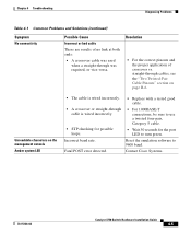
... incorrectly. • STP checking for the port LED to 9600 baud. Unreadable characters on page B-6. Fatal POST error detected. • Replace with a tested good cable. • For 1000BASE-T connections, be sure to use a twisted four-pair, Category 5 cable. •...; The cable is wired incorrectly. • A crossover or straight-through was required, or vice-versa. Contact Cisco Systems. 78-15136-02 Catalyst 3750 Switch Hardware Installation Guide 4-5 Chapter 4 Troubleshooting Diagnosing Problems Table 4-1 Common Problems and Solutions (continued) Symptom No connectivity ...
... incorrectly. • STP checking for the port LED to 9600 baud. Unreadable characters on page B-6. Fatal POST error detected. • Replace with a tested good cable. • For 1000BASE-T connections, be sure to use a twisted four-pair, Category 5 cable. •...; The cable is wired incorrectly. • A crossover or straight-through was required, or vice-versa. Contact Cisco Systems. 78-15136-02 Catalyst 3750 Switch Hardware Installation Guide 4-5 Chapter 4 Troubleshooting Diagnosing Problems Table 4-1 Common Problems and Solutions (continued) Symptom No connectivity ...

Hardware Installation Guide
Page 116
... recover from the switch, and replace it with a known good cable. Replace the SFP module with a Cisco-approved module. Secure the thumb screws on the errdisable recovery command. See Figure 3-35. Poor cable connection. Remove the StackWise cable, and inspect the cable and StackWise port for information on the StackWise cables. Catalyst 3750 Switch Hardware Installation Guide...
... recover from the switch, and replace it with a known good cable. Replace the SFP module with a Cisco-approved module. Secure the thumb screws on the errdisable recovery command. See Figure 3-35. Poor cable connection. Remove the StackWise cable, and inspect the cable and StackWise port for information on the StackWise cables. Catalyst 3750 Switch Hardware Installation Guide...
Hardware Installation Guide
Page 117
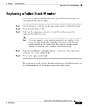
... function the same as were on the replacement switch. Step 4 Step 5 Make the same Ethernet and Gigabit Ethernet connections on the replacement switch (as the failed switch. 78-15136-02 Catalyst 3750 Switch Hardware Installation Guide 4-7 To assign the member number manually, refer to the stack. Power on the failed switch). The replacement switch will have the same configuration for any...
... function the same as were on the replacement switch. Step 4 Step 5 Make the same Ethernet and Gigabit Ethernet connections on the replacement switch (as the failed switch. 78-15136-02 Catalyst 3750 Switch Hardware Installation Guide 4-7 To assign the member number manually, refer to the stack. Power on the failed switch). The replacement switch will have the same configuration for any...

Hardware Installation Guide
Page 118
Replacing a Failed Stack Member Chapter 4 Troubleshooting Catalyst 3750 Switch Hardware Installation Guide 4-8 78-15136-02
Replacing a Failed Stack Member Chapter 4 Troubleshooting Catalyst 3750 Switch Hardware Installation Guide 4-8 78-15136-02

Hardware Installation Guide
Page 194
Index stacking the switches See also stacking starting the terminal emulation software D-9 table or shelf-mounting 3-36 wall mounting 3-32 warning E-5 See also procedures installing or replacing the unit warning E-12 installing SFP modules 3-41 to 3-43 IOS command-...methods for accessing the switch D-2 mode button 2-8 mounting, table or shelf 3-36 mounting, wall mounting 3-32 mounting brackets attaching 3-20 to 3-28 rack-mount 3-28 N noise, electrical 3-7 P packing list 3-7 PC, connecting to switch 3-9 performance problems, solving 4-3 IN-4 Catalyst 3750 Switch Hardware Installation Guide ...
Index stacking the switches See also stacking starting the terminal emulation software D-9 table or shelf-mounting 3-36 wall mounting 3-32 warning E-5 See also procedures installing or replacing the unit warning E-12 installing SFP modules 3-41 to 3-43 IOS command-...methods for accessing the switch D-2 mode button 2-8 mounting, table or shelf 3-36 mounting, wall mounting 3-32 mounting brackets attaching 3-20 to 3-28 rack-mount 3-28 N noise, electrical 3-7 P packing list 3-7 PC, connecting to switch 3-9 performance problems, solving 4-3 IN-4 Catalyst 3750 Switch Hardware Installation Guide ...