
Hardware Installation Guide
Page 8
... LED 2-9 RPS LED 2-9 Master LED 2-10 Port LEDs and Modes 2-10 Rear Panel Description 2-14 StackWise Ports 2-15 Power Connectors 2-16 Internal Power Supply Connector 2-16 Cisco RPS Connector 2-16 Console Port 2-17 Management Options 2-18 Network Configurations 2-19 Switch Installation 3-1 Preparing for Installation 3-1 Warnings 3-2 EMC Regulatory Statements 3-4 Catalyst 3750 Switch Hardware Installation Guide vi 78-15136-02
... LED 2-9 RPS LED 2-9 Master LED 2-10 Port LEDs and Modes 2-10 Rear Panel Description 2-14 StackWise Ports 2-15 Power Connectors 2-16 Internal Power Supply Connector 2-16 Cisco RPS Connector 2-16 Console Port 2-17 Management Options 2-18 Network Configurations 2-19 Switch Installation 3-1 Preparing for Installation 3-1 Warnings 3-2 EMC Regulatory Statements 3-4 Catalyst 3750 Switch Hardware Installation Guide vi 78-15136-02

Hardware Installation Guide
Page 9
... the Switch 3-19 Attaching Brackets to the Catalyst 3750G-24TS Switch 3-20 Attaching Brackets to the Catalyst 3750-24TS, 3750G-24T, 3750G-12S, and 3750-48TS Switches 3-25 Mounting the Switch in a Rack 3-28 Attaching the Cable Guide 3-30 Wall Mounting 3-32 Attaching the Brackets to the Switch for Wall-Mounting 3-32 Attaching the RPS Connector Cover 3-33 Mounting the Switch on...
... the Switch 3-19 Attaching Brackets to the Catalyst 3750G-24TS Switch 3-20 Attaching Brackets to the Catalyst 3750-24TS, 3750G-24T, 3750G-12S, and 3750-48TS Switches 3-25 Mounting the Switch in a Rack 3-28 Attaching the Cable Guide 3-30 Wall Mounting 3-32 Attaching the Brackets to the Switch for Wall-Mounting 3-32 Attaching the RPS Connector Cover 3-33 Mounting the Switch on...

Hardware Installation Guide
Page 10
... 4-7 A A P P E N D I X Technical Specifications A-1 B A P P E N D I X Connector and Cable Specifications B-1 Connector Specifications B-1 10/100/1000 Ports B-1 Connecting to 1000BASE-T Devices B-2 10/100 Ports B-3 SFP Module Ports B-5 Console Port B-6 Cable and Adapter Specifications B-6 Two Twisted-Pair Cable Pinouts B-6 Four Twisted-Pair Cable Pinouts for 10/100 Ports B-7 Four Twisted-Pair Cable Pinouts for 1000BASE-T Ports B-8 Catalyst 3750 Switch Hardware Installation...
... 4-7 A A P P E N D I X Technical Specifications A-1 B A P P E N D I X Connector and Cable Specifications B-1 Connector Specifications B-1 10/100/1000 Ports B-1 Connecting to 1000BASE-T Devices B-2 10/100 Ports B-3 SFP Module Ports B-5 Console Port B-6 Cable and Adapter Specifications B-6 Two Twisted-Pair Cable Pinouts B-6 Four Twisted-Pair Cable Pinouts for 10/100 Ports B-7 Four Twisted-Pair Cable Pinouts for 1000BASE-T Ports B-8 Catalyst 3750 Switch Hardware Installation...

Hardware Installation Guide
Page 31
Figure 1-3 Connecting the Power 1 STACK 1 STACK 2 CONSOLE 1.2A-100R>06A-A2T4,IN05GV0-~60 HZ DSCPIENPCPO+IUWF1T2IEESvDRFISO@NUR1MP3RPAAELNYMUOATLE 97176 1 Switch 2 2 AC power cord 78-15136-02 Catalyst 3750 Switch Hardware Installation Guide 1-3 Chapter 1 Using Express Setup Figure 1-2 Ethernet Cable Powering On the Switch 89887 Powering On the Switch Complete these steps to power on the switch: Step 1 Connect one end of the AC power cord to the power connector on the switch rear panel, as shown in Figure 1-3.
Figure 1-3 Connecting the Power 1 STACK 1 STACK 2 CONSOLE 1.2A-100R>06A-A2T4,IN05GV0-~60 HZ DSCPIENPCPO+IUWF1T2IEESvDRFISO@NUR1MP3RPAAELNYMUOATLE 97176 1 Switch 2 2 AC power cord 78-15136-02 Catalyst 3750 Switch Hardware Installation Guide 1-3 Chapter 1 Using Express Setup Figure 1-2 Ethernet Cable Powering On the Switch 89887 Powering On the Switch Complete these steps to power on the switch: Step 1 Connect one end of the AC power cord to the power connector on the switch rear panel, as shown in Figure 1-3.

Hardware Installation Guide
Page 46
...802.3ab. (The default setting is , the fastest line speed that is autonegotiate.) When set for this feature, refer to switches or hubs, use a crossover cable. For configuration information for autonegotiation, the port senses the speed and duplex settings of the ...Catalyst 3750 Switch Hardware Installation Guide 2-6 78-15136-02 Front Panel Description Chapter 2 Product Overview 10/100 and 10/100/1000 Ports You can use Category 3 or Category 4 cables. Note On switches running Cisco IOS Release 12.1(14)EA1 or later, you can use the mdix auto command in Appendix B, "Connector...
...802.3ab. (The default setting is , the fastest line speed that is autonegotiate.) When set for this feature, refer to switches or hubs, use a crossover cable. For configuration information for autonegotiation, the port senses the speed and duplex settings of the ...Catalyst 3750 Switch Hardware Installation Guide 2-6 78-15136-02 Front Panel Description Chapter 2 Product Overview 10/100 and 10/100/1000 Ports You can use Category 3 or Category 4 cables. Note On switches running Cisco IOS Release 12.1(14)EA1 or later, you can use the mdix auto command in Appendix B, "Connector...

Hardware Installation Guide
Page 47
You use Category 5 cable with LC or MT-RJ connectors to connect to a fiber-optic SFP module. You use fiber-optic cables with RJ-45 connectors to connect to other switches. The Catalyst 3750 models support these Cisco SFP options: • 1000BASE-LX • 1000BASE-SX &#...8226; 1000BASE-T For more information about these SFP modules, refer to establish fiber-optic connections. SFP Modules The Catalyst 3750 switch uses Gigabit ...
You use Category 5 cable with LC or MT-RJ connectors to connect to a fiber-optic SFP module. You use fiber-optic cables with RJ-45 connectors to connect to other switches. The Catalyst 3750 models support these Cisco SFP options: • 1000BASE-LX • 1000BASE-SX &#...8226; 1000BASE-T For more information about these SFP modules, refer to establish fiber-optic connections. SFP Modules The Catalyst 3750 switch uses Gigabit ...

Hardware Installation Guide
Page 54
... two StackWise ports. (See Figure 2-8 and Figure 2-9.) Figure 2-8 Catalyst 3750-24TS, 3750G-24T, 3750G-12S, and 3750-48TS Rear Panel 86548 STACK 1 STACK 2 CONSOLE 1.6A-100R>09A-A2T0,IN05GV0-~60 HZ [email protected] 1 23 4 5 1 StackWise ports 2 RJ-45 console port 3 Fan exhaust 4 AC power connector 5 RPS connector 2-14 Catalyst 3750 Switch Hardware Installation Guide 78-15136-02
... two StackWise ports. (See Figure 2-8 and Figure 2-9.) Figure 2-8 Catalyst 3750-24TS, 3750G-24T, 3750G-12S, and 3750-48TS Rear Panel 86548 STACK 1 STACK 2 CONSOLE 1.6A-100R>09A-A2T0,IN05GV0-~60 HZ [email protected] 1 23 4 5 1 StackWise ports 2 RJ-45 console port 3 Fan exhaust 4 AC power connector 5 RPS connector 2-14 Catalyst 3750 Switch Hardware Installation Guide 78-15136-02

Hardware Installation Guide
Page 55
... DSCPIENPCPO+IUWF1TI2EESvDRFISO@NUR1MP7RPAaELNYMUOATLE 1 23 4 5 1 StackWise ports 2 RJ-45 console port 3 Fan exhaust 4 AC power connector 5 RPS connector StackWise Ports The Catalyst 3750 switch ships with a 0.5-meter StackWise cable (72-2632-XX CABASY) that you can order these StackWise cables from your Cisco sales representative: • CAB-STACK-50CM= (0.5-meter cable) • CAB-STACK-1M= (1-meter cable...
... DSCPIENPCPO+IUWF1TI2EESvDRFISO@NUR1MP7RPAaELNYMUOATLE 1 23 4 5 1 StackWise ports 2 RJ-45 console port 3 Fan exhaust 4 AC power connector 5 RPS connector StackWise Ports The Catalyst 3750 switch ships with a 0.5-meter StackWise cable (72-2632-XX CABASY) that you can order these StackWise cables from your Cisco sales representative: • CAB-STACK-50CM= (0.5-meter cable) • CAB-STACK-1M= (1-meter cable...

Hardware Installation Guide
Page 56
... Catalyst 3750 Switch Hardware Installation Guide 78-15136-02 Warning Attach only the Cisco RPS (model PWR300-AC-RPS-N1) to the switch. Cisco RPS Connector Specific Cisco RPS modes support specific Catalyst 3750 switches: • Cisco RPS 300 (model PWR300-AC-RPS-N1) supports the Catalyst 3750-24TS, 3750G-24T, 3750G-12S, and 3750-48TS switches. • Cisco RPS 675 (model PWR675-AC-RPS-N1=) supports the Catalyst 3750...
... Catalyst 3750 Switch Hardware Installation Guide 78-15136-02 Warning Attach only the Cisco RPS (model PWR300-AC-RPS-N1) to the switch. Cisco RPS Connector Specific Cisco RPS modes support specific Catalyst 3750 switches: • Cisco RPS 300 (model PWR300-AC-RPS-N1) supports the Catalyst 3750-24TS, 3750G-24T, 3750G-12S, and 3750-48TS switches. • Cisco RPS 675 (model PWR675-AC-RPS-N1=) supports the Catalyst 3750...

Hardware Installation Guide
Page 57
.... For console port and adapter pinout information, see the "Connector and Cable Specifications" section on the Cisco RPS 675, refer to the Cisco RPS 675 Redundant Power System Hardware Installation Guide. Use the supplied RPS connector cable to connect the RPS to -DB-25 female DTE ... preventing loss of network traffic. For more information on page B-1. 78-15136-02 Catalyst 3750 Switch Hardware Installation Guide 2-17 You can order a kit (part number ACS-DSBUASYN=) containing that adapter from Cisco. The RPS is a redundant power system that can support six external network devices ...
.... For console port and adapter pinout information, see the "Connector and Cable Specifications" section on the Cisco RPS 675, refer to the Cisco RPS 675 Redundant Power System Hardware Installation Guide. Use the supplied RPS connector cable to connect the RPS to -DB-25 female DTE ... preventing loss of network traffic. For more information on page B-1. 78-15136-02 Catalyst 3750 Switch Hardware Installation Guide 2-17 You can order a kit (part number ACS-DSBUASYN=) containing that adapter from Cisco. The RPS is a redundant power system that can support six external network devices ...
Hardware Installation Guide
Page 67
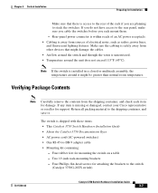
..., the temperature around the unit does not exceed 113°F (45°C). Rear-panel power connector is within reach of the rack if you rack mount them. - The switch is access to the rear of an AC power receptacle. • Cabling is missing or damaged..., contact your Cisco representative or reseller for support. Return all packing material to the rear panel, make sure you cable the switches before you are planning to the switch (Catalyst 3750G-24TS switch) 78-15136-02 Catalyst 3750 Switch Hardware Installation Guide 3-7 Four Phillips flat-head...
..., the temperature around the unit does not exceed 113°F (45°C). Rear-panel power connector is within reach of the rack if you rack mount them. - The switch is access to the rear of an AC power receptacle. • Cabling is missing or damaged..., contact your Cisco representative or reseller for support. Return all packing material to the rear panel, make sure you cable the switches before you are planning to the switch (Catalyst 3750G-24TS switch) 78-15136-02 Catalyst 3750 Switch Hardware Installation Guide 3-7 Four Phillips flat-head...

Hardware Installation Guide
Page 68
...screws for attaching the brackets to -DB-25 female DTE adapter. One redundant power system (RPS) connector cover (for Installation Chapter 3 Switch Installation - Verifying Switch Operation Before installing the switch in a rack, on a wall, or on page B-6. For console port and adapter pinout ...or shelf, you should power the switch and verify that adapter from Cisco. StackWise cable: 0.5-meter, 1-meter, or 3-meter cable. Note If you need to provide a RJ-45-to the switch (Catalyst 3750-24TS, 3750G-24T, and 3750-48TS switches) - To connect the switch console port to a terminal, you...
...screws for attaching the brackets to -DB-25 female DTE adapter. One redundant power system (RPS) connector cover (for Installation Chapter 3 Switch Installation - Verifying Switch Operation Before installing the switch in a rack, on a wall, or on page B-6. For console port and adapter pinout ...or shelf, you should power the switch and verify that adapter from Cisco. StackWise cable: 0.5-meter, 1-meter, or 3-meter cable. Note If you need to provide a RJ-45-to the switch (Catalyst 3750-24TS, 3750G-24T, and 3750-48TS switches) - To connect the switch console port to a terminal, you...

Hardware Installation Guide
Page 69
...data bits • 1 stop bit • No parity • None (flow control) After you have gained access to the switch, you are using a PC or terminal. 78-15136-02 Catalyst 3750 Switch Hardware Installation Guide 3-9 Start the terminal-emulation program if you can change the console baud rate through the Administration > Console Baud... the terminal. Attach the DB-9 female DTE adapter of the PC or terminal to match these steps to connect the PC or terminal to the switch: Step 1 Step 2 Step 3 Step 4 Configure the baud rate and character format of the RJ-45-to-DB-9 adapter cable to a PC,...
...data bits • 1 stop bit • No parity • None (flow control) After you have gained access to the switch, you are using a PC or terminal. 78-15136-02 Catalyst 3750 Switch Hardware Installation Guide 3-9 Start the terminal-emulation program if you can change the console baud rate through the Administration > Console Baud... the terminal. Attach the DB-9 female DTE adapter of the PC or terminal to match these steps to connect the PC or terminal to the switch: Step 1 Step 2 Step 3 Step 4 Configure the baud rate and character format of the RJ-45-to-DB-9 adapter cable to a PC,...
Hardware Installation Guide
Page 70
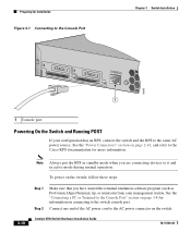
..., or minicom) from your configuration has an RPS, connect the switch and the RPS to the switch console port. See the "Power Connectors" section on page 2-16, and refer to the Cisco RPS documentation for more information. 3-10 Note Always put the RPS... section on page 3-8 for information on the switch. Preparing for Installation Figure 3-1 Connecting to the Console Port Chapter 3 Switch Installation STACK 1 STACK 2 CONSOLE 86685 1 1 Console port Powering On the Switch and Running POST If your management station. Catalyst 3750 Switch Hardware Installation Guide 78-15136-02
..., or minicom) from your configuration has an RPS, connect the switch and the RPS to the switch console port. See the "Power Connectors" section on page 2-16, and refer to the Cisco RPS documentation for more information. 3-10 Note Always put the RPS... section on page 3-8 for information on the switch. Preparing for Installation Figure 3-1 Connecting to the Console Port Chapter 3 Switch Installation STACK 1 STACK 2 CONSOLE 86685 1 1 Console port Powering On the Switch and Running POST If your management station. Catalyst 3750 Switch Hardware Installation Guide 78-15136-02

Hardware Installation Guide
Page 92
... 3-32 • Attaching the RPS Connector Cover, page 3-33 • Mounting the Switch on a Wall, page 3-34 Note The illustrations in this section show the Catalyst 3750G-24TS switch as an example. Follow the same steps to attach the second bracket to one side of the switch. All the Catalyst 3750 switches are wall-mounted following the same...
... 3-32 • Attaching the RPS Connector Cover, page 3-33 • Mounting the Switch on a Wall, page 3-34 Note The illustrations in this section show the Catalyst 3750G-24TS switch as an example. Follow the same steps to attach the second bracket to one side of the switch. All the Catalyst 3750 switches are wall-mounted following the same...

Hardware Installation Guide
Page 93
...-head screws to attach the RPS connector cover to the switch, install an RPS connector cover on the Catalyst 3750G-24TS Switch 86571 STACK 1 STACK 2 CONSOLE [email protected] 1 2 3 1 Phillips pan-head screws 3 RPS connector 2 RPS connector cover 78-15136-02 Catalyst 3750 Switch Hardware Installation Guide 3-33 Figure 3-31 Attaching the RPS Connector Cover on the back of the...
...-head screws to attach the RPS connector cover to the switch, install an RPS connector cover on the Catalyst 3750G-24TS Switch 86571 STACK 1 STACK 2 CONSOLE [email protected] 1 2 3 1 Phillips pan-head screws 3 RPS connector 2 RPS connector cover 78-15136-02 Catalyst 3750 Switch Hardware Installation Guide 3-33 Figure 3-31 Attaching the RPS Connector Cover on the back of the...

Hardware Installation Guide
Page 94
... attached securely to wall studs or to a firmly attached plywood mounting backboard. Installing the Switch Chapter 3 Switch Installation Figure 3-32 Attaching the RPS Connector Cover on the Catalyst 3750G-12S, 3750-24TS, 3750G-24T, and the 3750-48TS Switches STACK 1 STACK 2 CONSOLE 1.6A-100R>09A-A2T0,IN05GV0-~60 HZ [email protected] 1 2 3 1 Phillips pan-head screws 3 RPS...
... attached securely to wall studs or to a firmly attached plywood mounting backboard. Installing the Switch Chapter 3 Switch Installation Figure 3-32 Attaching the RPS Connector Cover on the Catalyst 3750G-12S, 3750-24TS, 3750G-24T, and the 3750-48TS Switches STACK 1 STACK 2 CONSOLE 1.6A-100R>09A-A2T0,IN05GV0-~60 HZ [email protected] 1 2 3 1 Phillips pan-head screws 3 RPS...

Hardware Installation Guide
Page 97
... 3 Step 4 Use the window in the StackWise cable to the switch software configuration guide or the switch command reference. Secure the screws tightly. Insert one end of the StackWise cable into the connector of the switch. Do not remove and insert the cable more often than is absolutely... Cisco-approved StackWise cable to StackWise Ports To use CMS, go to the "Launching the Switch Home Page" section on them to the StackWise ports: Step 1 Step 2 Remove the dust covers from the StackWise cables and StackWise ports, and store them from dust. 78-15136-02 Catalyst 3750 Switch ...
... 3 Step 4 Use the window in the StackWise cable to the switch software configuration guide or the switch command reference. Secure the screws tightly. Insert one end of the StackWise cable into the connector of the switch. Do not remove and insert the cable more often than is absolutely... Cisco-approved StackWise cable to StackWise Ports To use CMS, go to the "Launching the Switch Home Page" section on them to the StackWise ports: Step 1 Step 2 Remove the dust covers from the StackWise cables and StackWise ports, and store them from dust. 78-15136-02 Catalyst 3750 Switch ...

Hardware Installation Guide
Page 98
Also make sure to remove the StackWise cable from the StackWise port. Connecting StackWise Cable to StackWise Ports Figure 3-34 Inserting the StackWise Cable in a StackWise Port Chapter 3 Switch Installation STACK 1 STACK 2 CONSOLE 86549 When you remove the correct screws from the connector, make sure that you need to fully unscrew the screws before removing the connector. See Figure 3-35 for correct removal procedures and Figure 3-36 for incorrect removal procedures. 3-38 Catalyst 3750 Switch Hardware Installation Guide 78-15136-02
Also make sure to remove the StackWise cable from the StackWise port. Connecting StackWise Cable to StackWise Ports Figure 3-34 Inserting the StackWise Cable in a StackWise Port Chapter 3 Switch Installation STACK 1 STACK 2 CONSOLE 86549 When you remove the correct screws from the connector, make sure that you need to fully unscrew the screws before removing the connector. See Figure 3-35 for correct removal procedures and Figure 3-36 for incorrect removal procedures. 3-38 Catalyst 3750 Switch Hardware Installation Guide 78-15136-02

Hardware Installation Guide
Page 101
...connector, or the optical interfaces in the SFP module. Disconnect all cables before removing or installing an SFP module. Do not remove and insert SFP modules more often than is absolutely necessary. Figure 3-37 SFP Module with cables attached because of the SFP module. 78-15136-02 Catalyst 3750 Switch... Hardware Installation Guide 3-41 Find the send (TX) and receive (RX) markings that has a bale-clasp latch. Removing and installing an SFP module can shorten its useful life. Chapter 3 Switch Installation Installing and Removing ...
...connector, or the optical interfaces in the SFP module. Disconnect all cables before removing or installing an SFP module. Do not remove and insert SFP modules more often than is absolutely necessary. Figure 3-37 SFP Module with cables attached because of the SFP module. 78-15136-02 Catalyst 3750 Switch... Hardware Installation Guide 3-41 Find the send (TX) and receive (RX) markings that has a bale-clasp latch. Removing and installing an SFP module can shorten its useful life. Chapter 3 Switch Installation Installing and Removing ...