
Hardware Installation Guide
Page 8
... LED 2-9 RPS LED 2-9 Master LED 2-10 Port LEDs and Modes 2-10 Rear Panel Description 2-14 StackWise Ports 2-15 Power Connectors 2-16 Internal Power Supply Connector 2-16 Cisco RPS Connector 2-16 Console Port 2-17 Management Options 2-18 Network Configurations 2-19 Switch Installation 3-1 Preparing for Installation 3-1 Warnings 3-2 EMC Regulatory Statements 3-4 Catalyst 3750 Switch Hardware Installation Guide vi 78-15136-02
... LED 2-9 RPS LED 2-9 Master LED 2-10 Port LEDs and Modes 2-10 Rear Panel Description 2-14 StackWise Ports 2-15 Power Connectors 2-16 Internal Power Supply Connector 2-16 Cisco RPS Connector 2-16 Console Port 2-17 Management Options 2-18 Network Configurations 2-19 Switch Installation 3-1 Preparing for Installation 3-1 Warnings 3-2 EMC Regulatory Statements 3-4 Catalyst 3750 Switch Hardware Installation Guide vi 78-15136-02

Hardware Installation Guide
Page 9
... the Switch 3-19 Attaching Brackets to the Catalyst 3750G-24TS Switch 3-20 Attaching Brackets to the Catalyst 3750-24TS, 3750G-24T, 3750G-12S, and 3750-48TS Switches 3-25 Mounting the Switch in a Rack 3-28 Attaching the Cable Guide 3-30 Wall Mounting 3-32 Attaching the Brackets to the Switch for Wall-Mounting 3-32 Attaching the RPS Connector Cover 3-33 Mounting the Switch on...
... the Switch 3-19 Attaching Brackets to the Catalyst 3750G-24TS Switch 3-20 Attaching Brackets to the Catalyst 3750-24TS, 3750G-24T, 3750G-12S, and 3750-48TS Switches 3-25 Mounting the Switch in a Rack 3-28 Attaching the Cable Guide 3-30 Wall Mounting 3-32 Attaching the Brackets to the Switch for Wall-Mounting 3-32 Attaching the RPS Connector Cover 3-33 Mounting the Switch on...

Hardware Installation Guide
Page 10
... 4-7 A A P P E N D I X Technical Specifications A-1 B A P P E N D I X Connector and Cable Specifications B-1 Connector Specifications B-1 10/100/1000 Ports B-1 Connecting to 1000BASE-T Devices B-2 10/100 Ports B-3 SFP Module Ports B-5 Console Port B-6 Cable and Adapter Specifications B-6 Two Twisted-Pair Cable Pinouts B-6 Four Twisted-Pair Cable Pinouts for 10/100 Ports B-7 Four Twisted-Pair Cable Pinouts for 1000BASE-T Ports B-8 Catalyst 3750 Switch Hardware Installation...
... 4-7 A A P P E N D I X Technical Specifications A-1 B A P P E N D I X Connector and Cable Specifications B-1 Connector Specifications B-1 10/100/1000 Ports B-1 Connecting to 1000BASE-T Devices B-2 10/100 Ports B-3 SFP Module Ports B-5 Console Port B-6 Cable and Adapter Specifications B-6 Two Twisted-Pair Cable Pinouts B-6 Four Twisted-Pair Cable Pinouts for 10/100 Ports B-7 Four Twisted-Pair Cable Pinouts for 1000BASE-T Ports B-8 Catalyst 3750 Switch Hardware Installation...

Hardware Installation Guide
Page 31
Chapter 1 Using Express Setup Figure 1-2 Ethernet Cable Powering On the Switch 89887 Powering On the Switch Complete these steps to power on the switch: Step 1 Connect one end of the AC power cord to the power connector on the switch rear panel, as shown in Figure 1-3. Figure 1-3 Connecting the Power 1 STACK 1 STACK 2 CONSOLE 1.2A-100R>06A-A2T4,IN05GV0-~60 HZ DSCPIENPCPO+IUWF1T2IEESvDRFISO@NUR1MP3RPAAELNYMUOATLE 97176 1 Switch 2 2 AC power cord 78-15136-02 Catalyst 3750 Switch Hardware Installation Guide 1-3
Chapter 1 Using Express Setup Figure 1-2 Ethernet Cable Powering On the Switch 89887 Powering On the Switch Complete these steps to power on the switch: Step 1 Connect one end of the AC power cord to the power connector on the switch rear panel, as shown in Figure 1-3. Figure 1-3 Connecting the Power 1 STACK 1 STACK 2 CONSOLE 1.2A-100R>06A-A2T4,IN05GV0-~60 HZ DSCPIENPCPO+IUWF1T2IEESvDRFISO@NUR1MP3RPAAELNYMUOATLE 97176 1 Switch 2 2 AC power cord 78-15136-02 Catalyst 3750 Switch Hardware Installation Guide 1-3

Hardware Installation Guide
Page 46
... Note On switches running Cisco IOS Release 12.1(14)EA1 or later, you can also set these ports for speed and duplex autonegotiation in compliance with IEEE 802.3ab. (The default setting is autonegotiate.) When set for proper operation. Catalyst 3750 Switch Hardware Installation ...a crossover cable. For configuration information for the cables are described in Appendix B, "Connector and Cable Specifications." Pinouts for this feature, refer to the switch software configuration guide or the switch command reference. The automatic crossover feature is , the fastest line speed that the...
... Note On switches running Cisco IOS Release 12.1(14)EA1 or later, you can also set these ports for speed and duplex autonegotiation in compliance with IEEE 802.3ab. (The default setting is autonegotiate.) When set for proper operation. Catalyst 3750 Switch Hardware Installation ...a crossover cable. For configuration information for the cables are described in Appendix B, "Connector and Cable Specifications." Pinouts for this feature, refer to the switch software configuration guide or the switch command reference. The automatic crossover feature is , the fastest line speed that the...

Hardware Installation Guide
Page 47
... use the SFP modules for Gigabit uplink connections to a copper SFP module. You can use fiber-optic cables with RJ-45 connectors to connect to other switches. The Catalyst 3750 models support these Cisco SFP options: • 1000BASE-LX • 1000BASE-SX • 1000BASE-T For more information about these SFP modules, refer to establish fiber...
... use the SFP modules for Gigabit uplink connections to a copper SFP module. You can use fiber-optic cables with RJ-45 connectors to connect to other switches. The Catalyst 3750 models support these Cisco SFP options: • 1000BASE-LX • 1000BASE-SX • 1000BASE-T For more information about these SFP modules, refer to establish fiber...

Hardware Installation Guide
Page 54
... two StackWise ports. (See Figure 2-8 and Figure 2-9.) Figure 2-8 Catalyst 3750-24TS, 3750G-24T, 3750G-12S, and 3750-48TS Rear Panel 86548 STACK 1 STACK 2 CONSOLE 1.6A-100R>09A-A2T0,IN05GV0-~60 HZ [email protected] 1 23 4 5 1 StackWise ports 2 RJ-45 console port 3 Fan exhaust 4 AC power connector 5 RPS connector 2-14 Catalyst 3750 Switch Hardware Installation Guide 78-15136-02
... two StackWise ports. (See Figure 2-8 and Figure 2-9.) Figure 2-8 Catalyst 3750-24TS, 3750G-24T, 3750G-12S, and 3750-48TS Rear Panel 86548 STACK 1 STACK 2 CONSOLE 1.6A-100R>09A-A2T0,IN05GV0-~60 HZ [email protected] 1 23 4 5 1 StackWise ports 2 RJ-45 console port 3 Fan exhaust 4 AC power connector 5 RPS connector 2-14 Catalyst 3750 Switch Hardware Installation Guide 78-15136-02

Hardware Installation Guide
Page 55
... DSCPIENPCPO+IUWF1TI2EESvDRFISO@NUR1MP7RPAaELNYMUOATLE 1 23 4 5 1 StackWise ports 2 RJ-45 console port 3 Fan exhaust 4 AC power connector 5 RPS connector StackWise Ports The Catalyst 3750 switch ships with a 0.5-meter StackWise cable (72-2632-XX CABASY) that you can order these StackWise cables from your Cisco sales representative: • CAB-STACK-50CM= (0.5-meter cable) • CAB-STACK-1M= (1-meter cable...
... DSCPIENPCPO+IUWF1TI2EESvDRFISO@NUR1MP7RPAaELNYMUOATLE 1 23 4 5 1 StackWise ports 2 RJ-45 console port 3 Fan exhaust 4 AC power connector 5 RPS connector StackWise Ports The Catalyst 3750 switch ships with a 0.5-meter StackWise cable (72-2632-XX CABASY) that you can order these StackWise cables from your Cisco sales representative: • CAB-STACK-50CM= (0.5-meter cable) • CAB-STACK-1M= (1-meter cable...

Hardware Installation Guide
Page 56
... Overview Power Connectors The switch is an autoranging unit that supports input voltages between 100 and 240 VAC. Cisco RPS Connector Specific Cisco RPS modes support specific Catalyst 3750 switches: • Cisco RPS 300 (model PWR300-AC-RPS-N1) supports the Catalyst 3750-24TS, 3750G-24T, 3750G-12S, and 3750-48TS switches. • Cisco RPS 675 (model PWR675-AC-RPS-N1=) supports the Catalyst 3750 family of...
... Overview Power Connectors The switch is an autoranging unit that supports input voltages between 100 and 240 VAC. Cisco RPS Connector Specific Cisco RPS modes support specific Catalyst 3750 switches: • Cisco RPS 300 (model PWR300-AC-RPS-N1) supports the Catalyst 3750-24TS, 3750G-24T, 3750G-12S, and 3750-48TS switches. • Cisco RPS 675 (model PWR675-AC-RPS-N1=) supports the Catalyst 3750 family of...

Hardware Installation Guide
Page 57
... Power System Hardware Installation Guide. For console port and adapter pinout information, see the "Connector and Cable Specifications" section on the Cisco RPS 675, refer to the Cisco RPS 675 Redundant Power System Hardware Installation Guide. It automatically senses when the internal power ... the switch. Chapter 2 Product Overview Rear Panel Description Cisco RPS 675 The RPS is a redundant power system that can support six external network devices and provides power to one failed device at a time. For more information on page B-1. 78-15136-02 Catalyst 3750 Switch Hardware ...
... Power System Hardware Installation Guide. For console port and adapter pinout information, see the "Connector and Cable Specifications" section on the Cisco RPS 675, refer to the Cisco RPS 675 Redundant Power System Hardware Installation Guide. It automatically senses when the internal power ... the switch. Chapter 2 Product Overview Rear Panel Description Cisco RPS 675 The RPS is a redundant power system that can support six external network devices and provides power to one failed device at a time. For more information on page B-1. 78-15136-02 Catalyst 3750 Switch Hardware ...
Hardware Installation Guide
Page 67
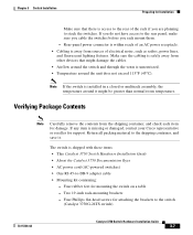
...are planning to the switch (Catalyst 3750G-24TS switch) 78-15136-02 Catalyst 3750 Switch Hardware Installation Guide 3-7 The switch is away from the shipping container, and check each item for mounting the switch on a table -...8226; Mounting kit containing: - Chapter 3 Switch Installation Preparing for Installation Make sure that might be greater than normal room temperature. Rear-panel power connector is installed in a closed or multirack ...• Airflow around the switch and through the vents is missing or damaged, contact your Cisco representative or reseller for support.
...are planning to the switch (Catalyst 3750G-24TS switch) 78-15136-02 Catalyst 3750 Switch Hardware Installation Guide 3-7 The switch is away from the shipping container, and check each item for mounting the switch on a table -...8226; Mounting kit containing: - Chapter 3 Switch Installation Preparing for Installation Make sure that might be greater than normal room temperature. Rear-panel power connector is installed in a closed or multirack ...• Airflow around the switch and through the vents is missing or damaged, contact your Cisco representative or reseller for support.

Hardware Installation Guide
Page 68
...Cisco. Verifying Switch Operation Before installing the switch in a rack, on a wall, or on a table or shelf, you don't specify the length of the mounting brackets - Preparing for wall-mounting brackets) - To connect the switch console port to a terminal, you need to provide a RJ-45-to a rack - One redundant power system (RPS) connector... is supplied by default. Two Phillips pan-head screws (for attaching the cable guide to the switch (Catalyst 3750-24TS, 3750G-24T, and 3750-48TS switches) - Four Phillips machine screws for attaching the brackets to -DB-25 female DTE adapter.
...Cisco. Verifying Switch Operation Before installing the switch in a rack, on a wall, or on a table or shelf, you don't specify the length of the mounting brackets - Preparing for wall-mounting brackets) - To connect the switch console port to a terminal, you need to provide a RJ-45-to a rack - One redundant power system (RPS) connector... is supplied by default. Two Phillips pan-head screws (for attaching the cable guide to the switch (Catalyst 3750-24TS, 3750G-24T, and 3750-48TS switches) - Four Phillips machine screws for attaching the brackets to -DB-25 female DTE adapter.

Hardware Installation Guide
Page 69
...the PC or terminal to the switch: Step 1 Step 2 Step 3 Step 4 Configure the baud rate and character format of the RJ-45-to-DB-9 adapter cable to a PC, or attach an appropriate adapter to -DB-9 adapter cable, insert the RJ-45 connector into the console port, as ...bits • 1 stop bit • No parity • None (flow control) After you have gained access to the switch, you are using a PC or terminal. 78-15136-02 Catalyst 3750 Switch Hardware Installation Guide 3-9 Start the terminal-emulation program if you can change the console baud rate through the Administration > Console Baud...
...the PC or terminal to the switch: Step 1 Step 2 Step 3 Step 4 Configure the baud rate and character format of the RJ-45-to-DB-9 adapter cable to a PC, or attach an appropriate adapter to -DB-9 adapter cable, insert the RJ-45 connector into the console port, as ...bits • 1 stop bit • No parity • None (flow control) After you have gained access to the switch, you are using a PC or terminal. 78-15136-02 Catalyst 3750 Switch Hardware Installation Guide 3-9 Start the terminal-emulation program if you can change the console baud rate through the Administration > Console Baud...
Hardware Installation Guide
Page 70
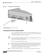
... to the Console Port Chapter 3 Switch Installation STACK 1 STACK 2 CONSOLE 86685 1 1 Console port Powering On the Switch and Running POST If your management station. See the "Power Connectors" section on page 2-16, and refer to the Cisco RPS documentation for information on connecting to...from your configuration has an RPS, connect the switch and the RPS to the AC power connector on the switch, follow these steps: Step 1 Step 2 Make sure that you are connecting devices to the switch console port. Catalyst 3750 Switch Hardware Installation Guide 78-15136-02 To power on...
... to the Console Port Chapter 3 Switch Installation STACK 1 STACK 2 CONSOLE 86685 1 1 Console port Powering On the Switch and Running POST If your management station. See the "Power Connectors" section on page 2-16, and refer to the Cisco RPS documentation for information on connecting to...from your configuration has an RPS, connect the switch and the RPS to the AC power connector on the switch, follow these steps: Step 1 Step 2 Make sure that you are connecting devices to the switch console port. Catalyst 3750 Switch Hardware Installation Guide 78-15136-02 To power on...

Hardware Installation Guide
Page 92
... Wall-Mounting 23 24 23X 24X Catalyst 3750 SERIES 25 26 27 28 1 Phillips truss-head screws 3-32 Catalyst 3750 Switch Hardware Installation Guide 1 78-15136-02 86687 Figure 3-30 Attaching the 19-inch Brackets for Wall-Mounting, page 3-32 • Attaching the RPS Connector Cover, page 3-33 • Mounting the Switch on a wall, follow the instructions...
... Wall-Mounting 23 24 23X 24X Catalyst 3750 SERIES 25 26 27 28 1 Phillips truss-head screws 3-32 Catalyst 3750 Switch Hardware Installation Guide 1 78-15136-02 86687 Figure 3-30 Attaching the 19-inch Brackets for Wall-Mounting, page 3-32 • Attaching the RPS Connector Cover, page 3-33 • Mounting the Switch on a wall, follow the instructions...

Hardware Installation Guide
Page 93
... the two Phillips pan-head screws to attach the RPS connector cover to the switch, install an RPS connector cover on the Catalyst 3750G-24TS Switch 86571 STACK 1 STACK 2 CONSOLE [email protected] 1 2 3 1 Phillips pan-head screws 3 RPS connector 2 RPS connector cover 78-15136-02 Catalyst 3750 Switch Hardware Installation Guide 3-33 Warning If an RPS is not connected...
... the two Phillips pan-head screws to attach the RPS connector cover to the switch, install an RPS connector cover on the Catalyst 3750G-24TS Switch 86571 STACK 1 STACK 2 CONSOLE [email protected] 1 2 3 1 Phillips pan-head screws 3 RPS connector 2 RPS connector cover 78-15136-02 Catalyst 3750 Switch Hardware Installation Guide 3-33 Warning If an RPS is not connected...

Hardware Installation Guide
Page 94
... attached securely to wall studs or to a firmly attached plywood mounting backboard. Installing the Switch Chapter 3 Switch Installation Figure 3-32 Attaching the RPS Connector Cover on the Catalyst 3750G-12S, 3750-24TS, 3750G-24T, and the 3750-48TS Switches STACK 1 STACK 2 CONSOLE 1.6A-100R>09A-A2T0,IN05GV0-~60 HZ [email protected] 1 2 3 1 Phillips pan-head screws 3 RPS...
... attached securely to wall studs or to a firmly attached plywood mounting backboard. Installing the Switch Chapter 3 Switch Installation Figure 3-32 Attaching the RPS Connector Cover on the Catalyst 3750G-12S, 3750-24TS, 3750G-24T, and the 3750-48TS Switches STACK 1 STACK 2 CONSOLE 1.6A-100R>09A-A2T0,IN05GV0-~60 HZ [email protected] 1 2 3 1 Phillips pan-head screws 3 RPS...

Hardware Installation Guide
Page 97
... end of the StackWise cable into the connector of the switch. Connecting StackWise Cable to StackWise Ports Follow these steps to connect the StackWise cable to the StackWise ports: Step 1 Step 2 Remove the dust covers from dust. 78-15136-02 Catalyst 3750 Switch Hardware Installation Guide 3-37 Chapter 3 Switch Installation Connecting StackWise Cable to StackWise Ports...
... end of the StackWise cable into the connector of the switch. Connecting StackWise Cable to StackWise Ports Follow these steps to connect the StackWise cable to the StackWise ports: Step 1 Step 2 Remove the dust covers from dust. 78-15136-02 Catalyst 3750 Switch Hardware Installation Guide 3-37 Chapter 3 Switch Installation Connecting StackWise Cable to StackWise Ports...

Hardware Installation Guide
Page 98
See Figure 3-35 for correct removal procedures and Figure 3-36 for incorrect removal procedures. 3-38 Catalyst 3750 Switch Hardware Installation Guide 78-15136-02 Also make sure that you need to fully unscrew the screws before removing the connector. Connecting StackWise Cable to StackWise Ports Figure 3-34 Inserting the StackWise Cable in a StackWise Port Chapter 3 Switch Installation STACK 1 STACK 2 CONSOLE 86549 When you remove the correct screws from the connector, make sure to remove the StackWise cable from the StackWise port.
See Figure 3-35 for correct removal procedures and Figure 3-36 for incorrect removal procedures. 3-38 Catalyst 3750 Switch Hardware Installation Guide 78-15136-02 Also make sure that you need to fully unscrew the screws before removing the connector. Connecting StackWise Cable to StackWise Ports Figure 3-34 Inserting the StackWise Cable in a StackWise Port Chapter 3 Switch Installation STACK 1 STACK 2 CONSOLE 86549 When you remove the correct screws from the connector, make sure to remove the StackWise cable from the StackWise port.

Hardware Installation Guide
Page 101
... 86575 To insert an SFP module into SFP Module Slots Figure 3-37 shows an SFP module that has a bale-clasp latch. Chapter 3 Switch Installation Installing and Removing SFP Modules For detailed instructions on installing, removing, and cabling the SFP module, refer to a bare metal surface on... the cables, the cable connector, or the optical interfaces in the SFP module. Do not remove and insert SFP modules more often than is absolutely necessary. Figure 3-37 SFP Module with cables attached because of the SFP module. 78-15136-02 Catalyst 3750 Switch Hardware Installation Guide 3-41 ...
... 86575 To insert an SFP module into SFP Module Slots Figure 3-37 shows an SFP module that has a bale-clasp latch. Chapter 3 Switch Installation Installing and Removing SFP Modules For detailed instructions on installing, removing, and cabling the SFP module, refer to a bare metal surface on... the cables, the cable connector, or the optical interfaces in the SFP module. Do not remove and insert SFP modules more often than is absolutely necessary. Figure 3-37 SFP Module with cables attached because of the SFP module. 78-15136-02 Catalyst 3750 Switch Hardware Installation Guide 3-41 ...