
Hardware Installation Guide
Page 9
... Powering Considerations 3-13 Cabling Considerations 3-14 Recommended Cabling Configurations 3-15 Installing the Switch 3-17 Rack Mounting 3-18 Removing Screws from the Switch 3-19 Attaching Brackets to the Catalyst 3750G-24TS Switch 3-20 Attaching Brackets to the Catalyst 3750-24TS, 3750G-24T, 3750G-12S, and 3750-48TS Switches 3-25 Mounting the Switch in a Rack 3-28 Attaching the Cable Guide 3-30 Wall Mounting 3-32 Attaching...
... Powering Considerations 3-13 Cabling Considerations 3-14 Recommended Cabling Configurations 3-15 Installing the Switch 3-17 Rack Mounting 3-18 Removing Screws from the Switch 3-19 Attaching Brackets to the Catalyst 3750G-24TS Switch 3-20 Attaching Brackets to the Catalyst 3750-24TS, 3750G-24T, 3750G-12S, and 3750-48TS Switches 3-25 Mounting the Switch in a Rack 3-28 Attaching the Cable Guide 3-30 Wall Mounting 3-32 Attaching...

Hardware Installation Guide
Page 42
...-12 SFP module slots • The switches support these SFP modules: - 1000BASE-SX - 1000BASE-LX - 1000BASE-T Note When installed in Catalyst 3750 switches, 1000BASE-T small form-factor pluggable (SFP) modules can stack up to the Catalyst 3750-24TS, 3750G-24T, 3750-48TS, and 3750G-12S switches. Features Chapter 2 Product Overview Figure 2-1 through Figure 2-5 show the Catalyst 3750 switches. These are hot-swappable • Power...
...-12 SFP module slots • The switches support these SFP modules: - 1000BASE-SX - 1000BASE-LX - 1000BASE-T Note When installed in Catalyst 3750 switches, 1000BASE-T small form-factor pluggable (SFP) modules can stack up to the Catalyst 3750-24TS, 3750G-24T, 3750-48TS, and 3750G-12S switches. Features Chapter 2 Product Overview Figure 2-1 through Figure 2-5 show the Catalyst 3750 switches. These are hot-swappable • Power...

Hardware Installation Guide
Page 43
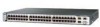
... are numbered 1 (left) and 2 (right). The ports are grouped in Figure 2-2 and Figure 2-3. Chapter 2 Product Overview Front Panel Description Note The Cisco RPS 300 does not support the Catalyst 3750G-24TS switch. - Figure 2-1 Catalyst 3750-24TS Front Panel 86541 SYST RPS MASTR STAT DUPLX SPEED STACK MODE 12 1X 34 56 78 9 10 11 12 11X...
... are numbered 1 (left) and 2 (right). The ports are grouped in Figure 2-2 and Figure 2-3. Chapter 2 Product Overview Front Panel Description Note The Cisco RPS 300 does not support the Catalyst 3750G-24TS switch. - Figure 2-1 Catalyst 3750-24TS Front Panel 86541 SYST RPS MASTR STAT DUPLX SPEED STACK MODE 12 1X 34 56 78 9 10 11 12 11X...

Hardware Installation Guide
Page 44
...9 10 11 12 11X 2X 12X 13 14 13X 15 16 17 18 19 20 21 22 23 24 23X 14X 24X 1 Catalyst 3750 SERIES 1 10/100/1000 ports Figure 2-3 Catalyst 3750G-24TS Front Panel Chapter 2 Product Overview 86543 86544 SYST RPS MASTR STAT DUPLX SPEED STACK MODE 12 1X 34 56 78 9 10... 16 17 18 19 20 21 22 23 24 23X 14X 24X Catalyst 3750 SERIES 25 26 27 28 1 2 1 10/100 ports 2 SFP module ports The Catalyst 3750G-12S SFP module slots are grouped in three sets of four, as shown in Figure 2-4. Catalyst 3750 Switch Hardware Installation Guide 2-4 78-15136-02 The ports are numbered 1 ...
...9 10 11 12 11X 2X 12X 13 14 13X 15 16 17 18 19 20 21 22 23 24 23X 14X 24X 1 Catalyst 3750 SERIES 1 10/100/1000 ports Figure 2-3 Catalyst 3750G-24TS Front Panel Chapter 2 Product Overview 86543 86544 SYST RPS MASTR STAT DUPLX SPEED STACK MODE 12 1X 34 56 78 9 10... 16 17 18 19 20 21 22 23 24 23X 14X 24X Catalyst 3750 SERIES 25 26 27 28 1 2 1 10/100 ports 2 SFP module ports The Catalyst 3750G-12S SFP module slots are grouped in three sets of four, as shown in Figure 2-4. Catalyst 3750 Switch Hardware Installation Guide 2-4 78-15136-02 The ports are numbered 1 ...

Hardware Installation Guide
Page 45
Port 3 is above port 4, and so on the far left, as shown in pairs. Figure 2-5 Catalyst 3750-48TS Front Panel 86542 SYST RPS MASTR STAT DUPLX SPEED STACK MODE 12 1X 2X 34 56 78 9 10 11 12 13 14...-02 Catalyst 3750 Switch Hardware Installation Guide 2-5 The first member of the pair (port 1) is above the second member (port 2) on . Chapter 2 Product Overview Figure 2-4 Catalyst 3750G-12S Front Panel Front Panel Description 97166 SYST RPS MASTR STAT DUPLX SPEED STACK MODE 1 2 3 4 5 6 7 8 9 10 Catalyst 3750 SERIES 11 12 1 1 SFP module ports The Catalyst 3750-48TS 10/...
Port 3 is above port 4, and so on the far left, as shown in pairs. Figure 2-5 Catalyst 3750-48TS Front Panel 86542 SYST RPS MASTR STAT DUPLX SPEED STACK MODE 12 1X 2X 34 56 78 9 10 11 12 13 14...-02 Catalyst 3750 Switch Hardware Installation Guide 2-5 The first member of the pair (port 1) is above the second member (port 2) on . Chapter 2 Product Overview Figure 2-4 Catalyst 3750G-12S Front Panel Front Panel Description 97166 SYST RPS MASTR STAT DUPLX SPEED STACK MODE 1 2 3 4 5 6 7 8 9 10 Catalyst 3750 SERIES 11 12 1 1 SFP module ports The Catalyst 3750-48TS 10/...

Hardware Installation Guide
Page 48
... 12X 1 Mode button 2 Stack LED 3 Speed LED 4 Duplex LED 5 Status LED 6 Master LED 7 RPS LED 8 System LED 9 Port LED 86545 Catalyst 3750 Switch Hardware Installation Guide 2-8 78-15136-02 All of the port modes. Figure 2-6 shows the Catalyst 3750-24TS, 3750G-24T, 3750G-24TS, 3750G-12S, and 3750-48TS LEDs and the Mode button that you use CMS to monitor...
... 12X 1 Mode button 2 Stack LED 3 Speed LED 4 Duplex LED 5 Status LED 6 Master LED 7 RPS LED 8 System LED 9 Port LED 86545 Catalyst 3750 Switch Hardware Installation Guide 2-8 78-15136-02 All of the port modes. Figure 2-6 shows the Catalyst 3750-24TS, 3750G-24T, 3750G-24TS, 3750G-12S, and 3750-48TS LEDs and the Mode button that you use CMS to monitor...

Hardware Installation Guide
Page 50
...Catalyst 3750G-24TS switches. Switch is highlighted. The port modes determine the type of the port LED colors also change to display the same selected mode. Table 2-4 lists the mode LEDs and their meanings. When you press the mode button on any one of the switches in the stack, all the other switches... LEDs, as a group or individually, display information about the switch and about the Cisco RPS 300, refer to interpret the port LED colors in the stack also display SPEED. 2-10 Catalyst 3750 Switch Hardware Installation Guide 78-15136-02 For more information about the ...
...Catalyst 3750G-24TS switches. Switch is highlighted. The port modes determine the type of the port LED colors also change to display the same selected mode. Table 2-4 lists the mode LEDs and their meanings. When you press the mode button on any one of the switches in the stack, all the other switches... LEDs, as a group or individually, display information about the switch and about the Cisco RPS 300, refer to interpret the port LED colors in the stack also display SPEED. 2-10 Catalyst 3750 Switch Hardware Installation Guide 78-15136-02 For more information about the ...

Hardware Installation Guide
Page 53
... bandwidth (32 Gbps). Chapter 2 Product Overview Front Panel Description • SFP port LEDs 3 and 4 on the Catalyst 3750-48TS switch show the status for StackWise ports 1 and 2, respectively. • SFP port LEDs 27 and 28 on the Catalyst 3750G-24TS switch show the status for StackWise ports 1 and 2, respectively. • The 10/100/1000 port LEDs 23...
... bandwidth (32 Gbps). Chapter 2 Product Overview Front Panel Description • SFP port LEDs 3 and 4 on the Catalyst 3750-48TS switch show the status for StackWise ports 1 and 2, respectively. • SFP port LEDs 27 and 28 on the Catalyst 3750G-24TS switch show the status for StackWise ports 1 and 2, respectively. • The 10/100/1000 port LEDs 23...

Hardware Installation Guide
Page 54
... two StackWise ports. (See Figure 2-8 and Figure 2-9.) Figure 2-8 Catalyst 3750-24TS, 3750G-24T, 3750G-12S, and 3750-48TS Rear Panel 86548 STACK 1 STACK 2 CONSOLE 1.6A-100R>09A-A2T0,IN05GV0-~60 HZ [email protected] 1 23 4 5 1 StackWise ports 2 RJ-45 console port 3 Fan exhaust 4 AC power connector 5 RPS connector 2-14 Catalyst 3750 Switch Hardware Installation Guide 78-15136-02
... two StackWise ports. (See Figure 2-8 and Figure 2-9.) Figure 2-8 Catalyst 3750-24TS, 3750G-24T, 3750G-12S, and 3750-48TS Rear Panel 86548 STACK 1 STACK 2 CONSOLE 1.6A-100R>09A-A2T0,IN05GV0-~60 HZ [email protected] 1 23 4 5 1 StackWise ports 2 RJ-45 console port 3 Fan exhaust 4 AC power connector 5 RPS connector 2-14 Catalyst 3750 Switch Hardware Installation Guide 78-15136-02

Hardware Installation Guide
Page 55
.... Equipment might be damaged if connected to similar Cisco equipment. Chapter 2 Product Overview Figure 2-9 Catalyst 3750G-24TS Rear Panel Rear Panel Description 86547 STACK 1 STACK 2 CONSOLE DSCPIENPCPO+IUWF1TI2EESvDRFISO@NUR1MP7RPAaELNYMUOATLE 1 23 4 5 1 StackWise ports 2 RJ-45 console port 3 Fan exhaust 4 AC power connector 5 RPS connector StackWise Ports The Catalyst 3750 switch ships with a 0.5-meter StackWise cable (72-2632...
.... Equipment might be damaged if connected to similar Cisco equipment. Chapter 2 Product Overview Figure 2-9 Catalyst 3750G-24TS Rear Panel Rear Panel Description 86547 STACK 1 STACK 2 CONSOLE DSCPIENPCPO+IUWF1TI2EESvDRFISO@NUR1MP7RPAaELNYMUOATLE 1 23 4 5 1 StackWise ports 2 RJ-45 console port 3 Fan exhaust 4 AC power connector 5 RPS connector StackWise Ports The Catalyst 3750 switch ships with a 0.5-meter StackWise cable (72-2632...

Hardware Installation Guide
Page 56
... the switch internal power supply should be connected to the RPS receptacle. 2-16 Catalyst 3750 Switch Hardware Installation Guide 78-15136-02 Cisco RPS Connector Specific Cisco RPS modes support specific Catalyst 3750 switches: • Cisco RPS 300 (model PWR300-AC-RPS-N1) supports the Catalyst 3750-24TS, 3750G-24T, 3750G-12S, and 3750-48TS switches. • Cisco RPS 675 (model PWR675-AC-RPS-N1=) supports the Catalyst 3750 family...
... the switch internal power supply should be connected to the RPS receptacle. 2-16 Catalyst 3750 Switch Hardware Installation Guide 78-15136-02 Cisco RPS Connector Specific Cisco RPS modes support specific Catalyst 3750 switches: • Cisco RPS 300 (model PWR300-AC-RPS-N1) supports the Catalyst 3750-24TS, 3750G-24T, 3750G-12S, and 3750-48TS switches. • Cisco RPS 675 (model PWR675-AC-RPS-N1=) supports the Catalyst 3750 family...
Hardware Installation Guide
Page 67
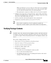
... lighting fixtures. The switch is missing or damaged, contact your Cisco representative or reseller for mounting the switch on a table - Four rubber feet for support. If you do not have access to the rear panel, make sure you cable the switches before you are planning to the switch (Catalyst 3750G-24TS switch) 78-15136-02 Catalyst 3750 Switch Hardware Installation Guide...
... lighting fixtures. The switch is missing or damaged, contact your Cisco representative or reseller for mounting the switch on a table - Four rubber feet for support. If you do not have access to the rear panel, make sure you cable the switches before you are planning to the switch (Catalyst 3750G-24TS switch) 78-15136-02 Catalyst 3750 Switch Hardware Installation Guide...

Hardware Installation Guide
Page 68
...-45-to the switch (Catalyst 3750-24TS, 3750G-24T, and 3750-48TS switches) - Catalyst 3750 Switch Hardware Installation Guide 3-8 78-15136-02 One redundant power system (RPS) connector cover (for Installation Chapter 3 Switch Installation - One cable guide and one black Phillips machine screw for attaching the cable guide to a terminal, you should power the switch and verify that adapter from Cisco. For console...
...-45-to the switch (Catalyst 3750-24TS, 3750G-24T, and 3750-48TS switches) - Catalyst 3750 Switch Hardware Installation Guide 3-8 78-15136-02 One redundant power system (RPS) connector cover (for Installation Chapter 3 Switch Installation - One cable guide and one black Phillips machine screw for attaching the cable guide to a terminal, you should power the switch and verify that adapter from Cisco. For console...

Hardware Installation Guide
Page 71
... turn amber for 2 seconds. If there is complete, only the SYST and STAT LEDs are installing the Catalyst 3750-24TS, 3750G-24T, 3750G-24T, 3750G-12S, or 3750-48TS switches, you can use the Cisco RPS 300. Warning Attach only the Cisco RPS 300 (model PWR300-AC-RPS-N1) to the RPS receptacle If you are green. When POST is...
... turn amber for 2 seconds. If there is complete, only the SYST and STAT LEDs are installing the Catalyst 3750-24TS, 3750G-24T, 3750G-24T, 3750G-12S, or 3750-48TS switches, you can use the Cisco RPS 300. Warning Attach only the Cisco RPS 300 (model PWR300-AC-RPS-N1) to the RPS receptacle If you are green. When POST is...

Hardware Installation Guide
Page 72
...-02 If you rack-mount them. • For concepts and procedures to manage switch stacks, refer to stack your Cisco supplier. Depending on page 2-15. The Catalyst 3750-24TS, 3750G-24TS, and 3750-48TS switches are the same depth, and the Catalyst 3750G-12S and 3750G-24T switches are planning to the rear of the rack if you don't specify the length...
...-02 If you rack-mount them. • For concepts and procedures to manage switch stacks, refer to stack your Cisco supplier. Depending on page 2-15. The Catalyst 3750-24TS, 3750G-24TS, and 3750-48TS switches are the same depth, and the Catalyst 3750G-12S and 3750G-24T switches are planning to the rear of the rack if you don't specify the length...

Hardware Installation Guide
Page 78
... provided with the switch. For the Catalyst 3750-24TS, 3750G-24T, 3750G-12S, and 3750-48TS switches, order part number RCKMNT-1RU=. 3-18 Catalyst 3750 Switch Hardware Installation Guide 78-15136-02 Installing the Switch Rack Mounting Chapter 3 Switch Installation Warning To prevent bodily injury when mounting or servicing this unit in these procedures: • Removing Screws from Cisco. For the Catalyst 3750G-24TS switches, order part...
... provided with the switch. For the Catalyst 3750-24TS, 3750G-24T, 3750G-12S, and 3750-48TS switches, order part number RCKMNT-1RU=. 3-18 Catalyst 3750 Switch Hardware Installation Guide 78-15136-02 Installing the Switch Rack Mounting Chapter 3 Switch Installation Warning To prevent bodily injury when mounting or servicing this unit in these procedures: • Removing Screws from Cisco. For the Catalyst 3750G-24TS switches, order part...

Hardware Installation Guide
Page 79
... the Catalyst 3750-24TS, 3750G-24T, and 3750-48TS Switches 86819 16 17 18 19 20 21 22 23 24 23X Catalyst 3750 SERIES 1 24X 2 Figure 3-11 Removing Screws from the Switch If you plan to remove the chassis screws in the switch chassis so that mounting brackets can be attached. Chapter 3 Switch Installation Installing the Switch Removing Screws from the Catalyst 3750G-12S Switch...
... the Catalyst 3750-24TS, 3750G-24T, and 3750-48TS Switches 86819 16 17 18 19 20 21 22 23 24 23X Catalyst 3750 SERIES 1 24X 2 Figure 3-11 Removing Screws from the Switch If you plan to remove the chassis screws in the switch chassis so that mounting brackets can be attached. Chapter 3 Switch Installation Installing the Switch Removing Screws from the Catalyst 3750G-12S Switch...

Hardware Installation Guide
Page 80
...Figure 3-18 show how to attach each type bracket to the opposite side. 3-20 Catalyst 3750 Switch Hardware Installation Guide 78-15136-02 Installing the Switch Chapter 3 Switch Installation Figure 3-12 shows how to the Catalyst 3750G-24TS Switch The bracket orientation and the brackets that you use depend on whether you are attaching ... part number 700-11523-XX; For 19-inch racks, use part number 700-12398-XX. Figure 3-12 Removing Screws from the 3750G-24TS Switch 86820 23 24 23X 24X Catalyst 3750 SERIES 25 26 27 28 Attaching Brackets to remove the chassis screws in a 1.5-RU...
...Figure 3-18 show how to attach each type bracket to the opposite side. 3-20 Catalyst 3750 Switch Hardware Installation Guide 78-15136-02 Installing the Switch Chapter 3 Switch Installation Figure 3-12 shows how to the Catalyst 3750G-24TS Switch The bracket orientation and the brackets that you use depend on whether you are attaching ... part number 700-11523-XX; For 19-inch racks, use part number 700-12398-XX. Figure 3-12 Removing Screws from the 3750G-24TS Switch 86820 23 24 23X 24X Catalyst 3750 SERIES 25 26 27 28 Attaching Brackets to remove the chassis screws in a 1.5-RU...
Hardware Installation Guide
Page 85
... bracket to the opposite side. Follow the same steps to attach the second bracket to one side of the switch. Chapter 3 Switch Installation Installing the Switch Attaching Brackets to the Catalyst 3750-24TS, 3750G-24T, 3750G-12S, and 3750-48TS Switches The bracket orientation and the brackets you use depend on whether you are attaching the brackets for 19-Inch...
... bracket to the opposite side. Follow the same steps to attach the second bracket to one side of the switch. Chapter 3 Switch Installation Installing the Switch Attaching Brackets to the Catalyst 3750-24TS, 3750G-24T, 3750G-12S, and 3750-48TS Switches The bracket orientation and the brackets you use depend on whether you are attaching the brackets for 19-Inch...

Hardware Installation Guide
Page 87
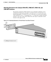
86563 Chapter 3 Switch Installation Figure 3-22 Attaching Brackets for 24-Inch Racks, Rear Panel Forward Installing the Switch 1.6A-100R>09A-A2T0,IN05GV0-~60 HZ [email protected] 1 1 Phillips flat-head screws Figure 3-23 Attaching Brackets for 19-Inch Telco Racks to Catalyst 3750-24TS, 3750G-24T, and 3750-48TS Switches 9 10 11 12 11X 12X 13 14 13X 15 16 17 18 19 20 21 22 23 24 23X 14X 24X Catalyst 3750 SERIES 1 2 1 1 Phillips flat-head screws 86564 78-15136-02 Catalyst 3750 Switch Hardware Installation Guide 3-27
86563 Chapter 3 Switch Installation Figure 3-22 Attaching Brackets for 24-Inch Racks, Rear Panel Forward Installing the Switch 1.6A-100R>09A-A2T0,IN05GV0-~60 HZ [email protected] 1 1 Phillips flat-head screws Figure 3-23 Attaching Brackets for 19-Inch Telco Racks to Catalyst 3750-24TS, 3750G-24T, and 3750-48TS Switches 9 10 11 12 11X 12X 13 14 13X 15 16 17 18 19 20 21 22 23 24 23X 14X 24X Catalyst 3750 SERIES 1 2 1 1 Phillips flat-head screws 86564 78-15136-02 Catalyst 3750 Switch Hardware Installation Guide 3-27


