
Hardware Installation Guide
Page 9
... Considerations 3-12 Powering Considerations 3-13 Cabling Considerations 3-14 Recommended Cabling Configurations 3-15 Installing the Switch 3-17 Rack Mounting 3-18 Removing Screws from the Switch 3-19 Attaching Brackets to the Catalyst 3750G-24TS Switch 3-20 Attaching Brackets to the Catalyst 3750-24TS, 3750G-24T, 3750G-12S, and 3750-48TS Switches 3-25 Mounting the Switch in a Rack 3-28 Attaching the Cable Guide 3-30 Wall Mounting 3-32 Attaching the...
... Considerations 3-12 Powering Considerations 3-13 Cabling Considerations 3-14 Recommended Cabling Configurations 3-15 Installing the Switch 3-17 Rack Mounting 3-18 Removing Screws from the Switch 3-19 Attaching Brackets to the Catalyst 3750G-24TS Switch 3-20 Attaching Brackets to the Catalyst 3750-24TS, 3750G-24T, 3750G-12S, and 3750-48TS Switches 3-25 Mounting the Switch in a Rack 3-28 Attaching the Cable Guide 3-30 Wall Mounting 3-32 Attaching the...

Hardware Installation Guide
Page 42
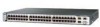
... Ethernet ports and 2 small form-factor pluggable (SFP) module slots - Catalyst 3750G-24T-24 10/100/1000 Ethernet ports - Catalyst 3750G-12S-12 SFP module slots • The switches support these SFP modules: - 1000BASE-SX - 1000BASE-LX - 1000BASE-T Note When installed in Catalyst 3750 switches, 1000BASE-T small form-factor pluggable (SFP) modules can stack up to the Catalyst 3750-24TS, 3750G-24T, 3750-48TS, and 3750G-12S switches.
... Ethernet ports and 2 small form-factor pluggable (SFP) module slots - Catalyst 3750G-24T-24 10/100/1000 Ethernet ports - Catalyst 3750G-12S-12 SFP module slots • The switches support these SFP modules: - 1000BASE-SX - 1000BASE-LX - 1000BASE-T Note When installed in Catalyst 3750 switches, 1000BASE-T small form-factor pluggable (SFP) modules can stack up to the Catalyst 3750-24TS, 3750G-24T, 3750-48TS, and 3750G-12S switches.

Hardware Installation Guide
Page 43
... 28. 78-15136-02 Catalyst 3750 Switch Hardware Installation Guide 2-3 Chapter 2 Product Overview Front Panel Description Note The Cisco RPS 300 does not support the Catalyst 3750G-24TS switch. - Connection for optional Cisco RPS 675 redundant power system that operates on the far left ) and 2 (right). The first member of Catalyst 3750 switches. Front Panel Description The Catalyst 3750-24TS 10/100 ports are grouped...
... 28. 78-15136-02 Catalyst 3750 Switch Hardware Installation Guide 2-3 Chapter 2 Product Overview Front Panel Description Note The Cisco RPS 300 does not support the Catalyst 3750G-24TS switch. - Connection for optional Cisco RPS 675 redundant power system that operates on the far left ) and 2 (right). The first member of Catalyst 3750 switches. Front Panel Description The Catalyst 3750-24TS 10/100 ports are grouped...

Hardware Installation Guide
Page 44
... 10 11 12 11X 2X 12X 13 14 13X 15 16 17 18 19 20 21 22 23 24 23X 14X 24X 1 Catalyst 3750 SERIES 1 10/100/1000 ports Figure 2-3 Catalyst 3750G-24TS Front Panel Chapter 2 Product Overview 86543 86544 SYST RPS MASTR STAT DUPLX SPEED STACK MODE 12 1X 34 56 78 9 10 ...16 17 18 19 20 21 22 23 24 23X 14X 24X Catalyst 3750 SERIES 25 26 27 28 1 2 1 10/100 ports 2 SFP module ports The Catalyst 3750G-12S SFP module slots are grouped in three sets of four, as shown in Figure 2-4. Catalyst 3750 Switch Hardware Installation Guide 2-4 78-15136-02 The ports are numbered ...
... 10 11 12 11X 2X 12X 13 14 13X 15 16 17 18 19 20 21 22 23 24 23X 14X 24X 1 Catalyst 3750 SERIES 1 10/100/1000 ports Figure 2-3 Catalyst 3750G-24TS Front Panel Chapter 2 Product Overview 86543 86544 SYST RPS MASTR STAT DUPLX SPEED STACK MODE 12 1X 34 56 78 9 10 ...16 17 18 19 20 21 22 23 24 23X 14X 24X Catalyst 3750 SERIES 25 26 27 28 1 2 1 10/100 ports 2 SFP module ports The Catalyst 3750G-12S SFP module slots are grouped in three sets of four, as shown in Figure 2-4. Catalyst 3750 Switch Hardware Installation Guide 2-4 78-15136-02 The ports are numbered ...

Hardware Installation Guide
Page 48
... 1 Mode button 2 Stack LED 3 Speed LED 4 Duplex LED 5 Status LED 6 Master LED 7 RPS LED 8 System LED 9 Port LED 86545 Catalyst 3750 Switch Hardware Installation Guide 2-8 78-15136-02 Figure 2-6 shows the Catalyst 3750-24TS, 3750G-24T, 3750G-24TS, 3750G-12S, and 3750-48TS LEDs and the Mode button that you use to select one of the LEDs described in this section are visible...
... 1 Mode button 2 Stack LED 3 Speed LED 4 Duplex LED 5 Status LED 6 Master LED 7 RPS LED 8 System LED 9 Port LED 86545 Catalyst 3750 Switch Hardware Installation Guide 2-8 78-15136-02 Figure 2-6 shows the Catalyst 3750-24TS, 3750G-24T, 3750G-24TS, 3750G-12S, and 3750-48TS LEDs and the Mode button that you use to select one of the LEDs described in this section are visible...

Hardware Installation Guide
Page 50
...has a port LED. When you press the mode button on any one of the switches in the stack, all the other switches in the stack change . Table 2-5 explains how to the Cisco RPS 300 Redundant Power System Hardware Installation Guide. Front Panel Description Chapter 2 Product Overview...the port LED colors also change to display SPEED, all the switches in the stack also display SPEED. 2-10 Catalyst 3750 Switch Hardware Installation Guide 78-15136-02 Note The Cisco RPS 300 does not support the Catalyst 3750G-24TS switches. Master LED The Master LED shows the stack master status. An...
...has a port LED. When you press the mode button on any one of the switches in the stack, all the other switches in the stack change . Table 2-5 explains how to the Cisco RPS 300 Redundant Power System Hardware Installation Guide. Front Panel Description Chapter 2 Product Overview...the port LED colors also change to display SPEED, all the switches in the stack also display SPEED. 2-10 Catalyst 3750 Switch Hardware Installation Guide 78-15136-02 Note The Cisco RPS 300 does not support the Catalyst 3750G-24TS switches. Master LED The Master LED shows the stack master status. An...

Hardware Installation Guide
Page 53
...Product Overview Front Panel Description • SFP port LEDs 3 and 4 on the Catalyst 3750-48TS switch show the status for StackWise ports 1 and 2, respectively. • SFP port LEDs 27 and 28 on the Catalyst 3750G-24TS switch show the status for StackWise ports 1 and 2, respectively. • The 10/100.../1000 port LEDs 23 and 24 on the Catalyst 3750G-24T switch show the status for StackWise ports 1 and 2, respectively. • ...
...Product Overview Front Panel Description • SFP port LEDs 3 and 4 on the Catalyst 3750-48TS switch show the status for StackWise ports 1 and 2, respectively. • SFP port LEDs 27 and 28 on the Catalyst 3750G-24TS switch show the status for StackWise ports 1 and 2, respectively. • The 10/100.../1000 port LEDs 23 and 24 on the Catalyst 3750G-24T switch show the status for StackWise ports 1 and 2, respectively. • ...

Hardware Installation Guide
Page 54
... port, and two StackWise ports. (See Figure 2-8 and Figure 2-9.) Figure 2-8 Catalyst 3750-24TS, 3750G-24T, 3750G-12S, and 3750-48TS Rear Panel 86548 STACK 1 STACK 2 CONSOLE 1.6A-100R>09A-A2T0,IN05GV0-~60 HZ [email protected] 1 23 4 5 1 StackWise ports 2 RJ-45 console port 3 Fan exhaust 4 AC power connector 5 RPS connector 2-14 Catalyst 3750 Switch Hardware Installation Guide 78-15136-02
... port, and two StackWise ports. (See Figure 2-8 and Figure 2-9.) Figure 2-8 Catalyst 3750-24TS, 3750G-24T, 3750G-12S, and 3750-48TS Rear Panel 86548 STACK 1 STACK 2 CONSOLE 1.6A-100R>09A-A2T0,IN05GV0-~60 HZ [email protected] 1 23 4 5 1 StackWise ports 2 RJ-45 console port 3 Fan exhaust 4 AC power connector 5 RPS connector 2-14 Catalyst 3750 Switch Hardware Installation Guide 78-15136-02

Hardware Installation Guide
Page 55
...-3M), and connect only to other nonapproved Cisco cables or equipment. Chapter 2 Product Overview Figure 2-9 Catalyst 3750G-24TS Rear Panel Rear Panel Description 86547 STACK 1 STACK 2 CONSOLE DSCPIENPCPO+IUWF1TI2EESvDRFISO@NUR1MP7RPAaELNYMUOATLE 1 23 4 5 1 StackWise ports 2 RJ-45 console port 3 Fan exhaust 4 AC power connector 5 RPS connector StackWise Ports The Catalyst 3750 switch ships with a 0.5-meter StackWise cable (72-2632...
...-3M), and connect only to other nonapproved Cisco cables or equipment. Chapter 2 Product Overview Figure 2-9 Catalyst 3750G-24TS Rear Panel Rear Panel Description 86547 STACK 1 STACK 2 CONSOLE DSCPIENPCPO+IUWF1TI2EESvDRFISO@NUR1MP7RPAaELNYMUOATLE 1 23 4 5 1 StackWise ports 2 RJ-45 console port 3 Fan exhaust 4 AC power connector 5 RPS connector StackWise Ports The Catalyst 3750 switch ships with a 0.5-meter StackWise cable (72-2632...

Hardware Installation Guide
Page 56
... through the internal power supply. Cisco RPS Connector Specific Cisco RPS modes support specific Catalyst 3750 switches: • Cisco RPS 300 (model PWR300-AC-RPS-N1) supports the Catalyst 3750-24TS, 3750G-24T, 3750G-12S, and 3750-48TS switches. • Cisco RPS 675 (model PWR675-AC-RPS-N1=) supports the Catalyst 3750 family of 300W. Note The Cisco RPS 300 does not support the Catalyst 3750G-24TS switches. Use the supplied RPS connector...
... through the internal power supply. Cisco RPS Connector Specific Cisco RPS modes support specific Catalyst 3750 switches: • Cisco RPS 300 (model PWR300-AC-RPS-N1) supports the Catalyst 3750-24TS, 3750G-24T, 3750G-12S, and 3750-48TS switches. • Cisco RPS 675 (model PWR675-AC-RPS-N1=) supports the Catalyst 3750 family of 300W. Note The Cisco RPS 300 does not support the Catalyst 3750G-24TS switches. Use the supplied RPS connector...
Hardware Installation Guide
Page 67
... damage the cables. • Airflow around the switch and through the vents is unrestricted. • Temperature around it . If any item is missing or damaged, contact your Cisco representative or reseller for Installation Make sure that might... receptacle. • Cabling is shipped with these items: • This Catalyst 3750 Switch Hardware Installation Guide • About the Catalyst 3750 Documentation flyer • AC power cord (AC-powered switches) • One RJ-45-to the switch (Catalyst 3750G-24TS switch) 78-15136-02 Catalyst 3750 Switch Hardware Installation Guide 3-7
... damage the cables. • Airflow around the switch and through the vents is unrestricted. • Temperature around it . If any item is missing or damaged, contact your Cisco representative or reseller for Installation Make sure that might... receptacle. • Cabling is shipped with these items: • This Catalyst 3750 Switch Hardware Installation Guide • About the Catalyst 3750 Documentation flyer • AC power cord (AC-powered switches) • One RJ-45-to the switch (Catalyst 3750G-24TS switch) 78-15136-02 Catalyst 3750 Switch Hardware Installation Guide 3-7

Hardware Installation Guide
Page 68
... the switch (Catalyst 3750-24TS, 3750G-24T, and 3750-48TS switches) - Verifying Switch Operation Before installing the switch in a rack, on a wall, or on a table or shelf, you don't specify the length of the mounting brackets - Catalyst 3750 Switch Hardware Installation Guide 3-8 78-15136-02 Preparing for wall mounting) - Note If you should power the switch and verify that adapter from Cisco. To connect the switch console...
... the switch (Catalyst 3750-24TS, 3750G-24T, and 3750-48TS switches) - Verifying Switch Operation Before installing the switch in a rack, on a wall, or on a table or shelf, you don't specify the length of the mounting brackets - Catalyst 3750 Switch Hardware Installation Guide 3-8 78-15136-02 Preparing for wall mounting) - Note If you should power the switch and verify that adapter from Cisco. To connect the switch console...

Hardware Installation Guide
Page 72
...Catalyst 3750-24TS, 3750G-24TS, and 3750-48TS switches are the same depth, and the Catalyst 3750G-12S and 3750G-24T switches are planning to stack the switches. Stacking switches of the same size together will make sure you cable the switches before you rack-mount them. • For concepts and procedures to manage switch... Configurations, page 3-15 Planning Considerations Before connecting the Catalyst 3750 switches in a stack, observe these planning considerations: • Size of recommended configurations. • Access to stack your Cisco supplier. If you do not have , you might...
...Catalyst 3750-24TS, 3750G-24TS, and 3750-48TS switches are the same depth, and the Catalyst 3750G-12S and 3750G-24T switches are planning to stack the switches. Stacking switches of the same size together will make sure you cable the switches before you rack-mount them. • For concepts and procedures to manage switch... Configurations, page 3-15 Planning Considerations Before connecting the Catalyst 3750 switches in a stack, observe these planning considerations: • Size of recommended configurations. • Access to stack your Cisco supplier. If you do not have , you might...

Hardware Installation Guide
Page 78
... Screws from Cisco. For the Catalyst 3750-24TS, 3750G-24T, 3750G-12S, and 3750-48TS switches, order part number RCKMNT-1RU=. 3-18 Catalyst 3750 Switch Hardware Installation Guide 78-15136-02 Installing the Switch Rack Mounting Chapter 3 Switch Installation Warning To prevent bodily injury when mounting or servicing this unit in a partially filled rack, load the rack from the bottom to the Catalyst 3750-24TS, 3750G-24T, 3750G-12S, and 3750-48TS Switches, page...
... Screws from Cisco. For the Catalyst 3750-24TS, 3750G-24T, 3750G-12S, and 3750-48TS switches, order part number RCKMNT-1RU=. 3-18 Catalyst 3750 Switch Hardware Installation Guide 78-15136-02 Installing the Switch Rack Mounting Chapter 3 Switch Installation Warning To prevent bodily injury when mounting or servicing this unit in a partially filled rack, load the rack from the bottom to the Catalyst 3750-24TS, 3750G-24T, 3750G-12S, and 3750-48TS Switches, page...

Hardware Installation Guide
Page 80
... number 700-12398-XX. Figure 3-12 Removing Screws from the 3750G-24TS Switch 86820 23 24 23X 24X Catalyst 3750 SERIES 25 26 27 28 Attaching Brackets to one side of the switch. Installing the Switch Chapter 3 Switch Installation Figure 3-12 shows how to the opposite side. 3-20 Catalyst 3750 Switch Hardware Installation Guide 78-15136-02 Follow the same steps...
... number 700-12398-XX. Figure 3-12 Removing Screws from the 3750G-24TS Switch 86820 23 24 23X 24X Catalyst 3750 SERIES 25 26 27 28 Attaching Brackets to one side of the switch. Installing the Switch Chapter 3 Switch Installation Figure 3-12 shows how to the opposite side. 3-20 Catalyst 3750 Switch Hardware Installation Guide 78-15136-02 Follow the same steps...

Hardware Installation Guide
Page 89
... Figure 3-26 Mounting the Catalyst 3750G-24TS Switch in a Rack Installing the Switch SYST RPS MASTR STAT DUPLX SPEED STACK MODE 12 1X 34 56 78 9 10 11 12 11X 2X 12X 1 13 14 13X 15 16 17 18 19 20 21 22 23 24 23X 14X 24X Catalyst 3750 SERIES 25 26 27 28 ...86566 1 Phillips machine screws Figure 3-27 Mounting the Catalyst 3750-24TS, 3750G-24T, 3750G-12S, and 3750-48TS Switches in a Rack SYST RPS MASTR STAT DUPLX SPYESETD SRTPASCK MODE MASTR STAT DUPLX SPEED STACK MODE 1 ...
... Figure 3-26 Mounting the Catalyst 3750G-24TS Switch in a Rack Installing the Switch SYST RPS MASTR STAT DUPLX SPEED STACK MODE 12 1X 34 56 78 9 10 11 12 11X 2X 12X 1 13 14 13X 15 16 17 18 19 20 21 22 23 24 23X 14X 24X Catalyst 3750 SERIES 25 26 27 28 ...86566 1 Phillips machine screws Figure 3-27 Mounting the Catalyst 3750-24TS, 3750G-24T, 3750G-12S, and 3750-48TS Switches in a Rack SYST RPS MASTR STAT DUPLX SPYESETD SRTPASCK MODE MASTR STAT DUPLX SPEED STACK MODE 1 ...

Hardware Installation Guide
Page 92
... Wall-Mounting 23 24 23X 24X Catalyst 3750 SERIES 25 26 27 28 1 Phillips truss-head screws 3-32 Catalyst 3750 Switch Hardware Installation Guide 1 78-15136-02 86687 Installing the Switch Chapter 3 Switch Installation Wall Mounting To install the switch on a Wall, page 3-34 Note The illustrations in this section show the Catalyst 3750G-24TS switch as an example. Follow the same...
... Wall-Mounting 23 24 23X 24X Catalyst 3750 SERIES 25 26 27 28 1 Phillips truss-head screws 3-32 Catalyst 3750 Switch Hardware Installation Guide 1 78-15136-02 86687 Installing the Switch Chapter 3 Switch Installation Wall Mounting To install the switch on a Wall, page 3-34 Note The illustrations in this section show the Catalyst 3750G-24TS switch as an example. Follow the same...

Hardware Installation Guide
Page 93
... an RPS with your switch, use the two Phillips pan-head screws to attach the RPS connector cover to the switch, install an RPS connector cover on the Catalyst 3750G-24TS Switch 86571 STACK 1 STACK 2 CONSOLE [email protected] 1 2 3 1 Phillips pan-head screws 3 RPS connector 2 RPS connector cover 78-15136-02 Catalyst 3750 Switch Hardware Installation Guide 3-33...
... an RPS with your switch, use the two Phillips pan-head screws to attach the RPS connector cover to the switch, install an RPS connector cover on the Catalyst 3750G-24TS Switch 86571 STACK 1 STACK 2 CONSOLE [email protected] 1 2 3 1 Phillips pan-head screws 3 RPS connector 2 RPS connector cover 78-15136-02 Catalyst 3750 Switch Hardware Installation Guide 3-33...

Hardware Installation Guide
Page 121
Appendix A Technical Specifications Table A-2 Specifications for the Catalyst 3750-24TS Switch (continued) Environmental Ranges Physical Dimensions Weight 8 lb (3.6 kg) Dimensions (H x D x W) 1.73 x 11.83 x 17.5 in. (4.39 x 30.05 x 44.45 cm) Table A-3 Specifications for the Catalyst 3750G-24T Switch Environmental Ranges Operating temperature 32 to 113°F (0 to 45°C) Storage temperature -13 to 158&#... Dimensions Weight 10 lb (4.55 kg) Dimensions (H x D x W) 1.73 x 12.83 x 17.5 in. (4.39 x 32.59 x 44.45 cm) 78-15136-02 Catalyst 3750 Switch Hardware Installation Guide A-3
Appendix A Technical Specifications Table A-2 Specifications for the Catalyst 3750-24TS Switch (continued) Environmental Ranges Physical Dimensions Weight 8 lb (3.6 kg) Dimensions (H x D x W) 1.73 x 11.83 x 17.5 in. (4.39 x 30.05 x 44.45 cm) Table A-3 Specifications for the Catalyst 3750G-24T Switch Environmental Ranges Operating temperature 32 to 113°F (0 to 45°C) Storage temperature -13 to 158&#... Dimensions Weight 10 lb (4.55 kg) Dimensions (H x D x W) 1.73 x 12.83 x 17.5 in. (4.39 x 32.59 x 44.45 cm) 78-15136-02 Catalyst 3750 Switch Hardware Installation Guide A-3

Hardware Installation Guide
Page 122
Appendix A Technical Specifications Table A-4 Specifications for the Catalyst 3750G-24TS Switch Environmental Ranges Operating temperature 32 to 113°F (0 to 45°C) Storage temperature -13 to 158°F (-25 to 70°C) ...Dimensions Weight 12.5 lb (5.68 kg) Dimensions (H x D x W) 2.59 x 11.60 x 17.5 in. (6.59 x 29.46 x 44.45 cm) Table A-5 Specifications for the Catalyst 3750-48TS Switch Environmental Ranges Operating temperature Storage temperature Relative humidity Operating altitude Storage altitude Power Requirements AC input voltage 32 to 113°F (0 to 45°C) -13...
Appendix A Technical Specifications Table A-4 Specifications for the Catalyst 3750G-24TS Switch Environmental Ranges Operating temperature 32 to 113°F (0 to 45°C) Storage temperature -13 to 158°F (-25 to 70°C) ...Dimensions Weight 12.5 lb (5.68 kg) Dimensions (H x D x W) 2.59 x 11.60 x 17.5 in. (6.59 x 29.46 x 44.45 cm) Table A-5 Specifications for the Catalyst 3750-48TS Switch Environmental Ranges Operating temperature Storage temperature Relative humidity Operating altitude Storage altitude Power Requirements AC input voltage 32 to 113°F (0 to 45°C) -13...


