
Hardware Installation Guide
Page 2
...area is an adaptation of a program developed by FCC regulations, and you may radiate radio-frequency energy. THE SPECIFICATIONS AND INFORMATION REGARDING THE PRODUCTS IN THIS MANUAL ARE SUBJECT TO CHANGE WITHOUT NOTICE. ALL STATEMENTS, INFORMATION, AND ... are designed to radio communications. and Aironet, ASIST, BPX, Catalyst, CCDA, CCDP, CCIE, CCNA, CCNP, Cisco, the Cisco Certified Internetwork Expert logo, Cisco IOS, the Cisco IOS logo, Cisco Press, Cisco Systems, Cisco Systems Capital, the Cisco Systems logo, Empowering the Internet Generation, Enterprise/Solver, EtherChannel, ...
...area is an adaptation of a program developed by FCC regulations, and you may radiate radio-frequency energy. THE SPECIFICATIONS AND INFORMATION REGARDING THE PRODUCTS IN THIS MANUAL ARE SUBJECT TO CHANGE WITHOUT NOTICE. ALL STATEMENTS, INFORMATION, AND ... are designed to radio communications. and Aironet, ASIST, BPX, Catalyst, CCDA, CCDP, CCIE, CCNA, CCNP, Cisco, the Cisco Certified Internetwork Expert logo, Cisco IOS, the Cisco IOS logo, Cisco Press, Cisco Systems, Cisco Systems Capital, the Cisco Systems logo, Empowering the Internet Generation, Enterprise/Solver, EtherChannel, ...

Hardware Installation Guide
Page 7
... 2-19 Installing the Switch on a Wall 2-20 Attaching the Brackets to the Switch 2-21 Mounting the Switch to a Wall 2-22 Powering On the Switch and Running POST 2-24 Connecting to DC Power 2-25 Preparing for Installation 2-25 Grounding the Switch 2-26 Wiring the... Go Next 2-43 Troubleshooting 3-1 Understanding POST Results 3-1 Correcting Module POST Failures 3-2 Diagnosing Problems 3-3 Technical Specifications A-1 Connectors and Cable Specifications B-1 Connector Specifications B-1 10/100 Ports B-1 100BASE-FX Ports B-2 Contents 78-6461-04 Catalyst 2900 Series XL Hardware Installation Guide vii
... 2-19 Installing the Switch on a Wall 2-20 Attaching the Brackets to the Switch 2-21 Mounting the Switch to a Wall 2-22 Powering On the Switch and Running POST 2-24 Connecting to DC Power 2-25 Preparing for Installation 2-25 Grounding the Switch 2-26 Wiring the... Go Next 2-43 Troubleshooting 3-1 Understanding POST Results 3-1 Correcting Module POST Failures 3-2 Diagnosing Problems 3-3 Technical Specifications A-1 Connectors and Cable Specifications B-1 Connector Specifications B-1 10/100 Ports B-1 100BASE-FX Ports B-2 Contents 78-6461-04 Catalyst 2900 Series XL Hardware Installation Guide vii

Hardware Installation Guide
Page 8
... Ports B-3 Console Port B-3 Cable and Adapter Specifications B-4 Crossover and Straight-Through Cable Pinouts B-4 RJ-21 Cable Pinouts B-5 Console Port B-5 Identifying a Rollover Cable B-6 Connecting to a PC B-6 Connecting to a Terminal B-7 Translated Safety Warnings C-1 Attaching the Cisco RPS (model PWR600-AC-RPS) C-1 Attaching the Cisco RPS (model PWR300-AC-RPS-N1) C-2 Qualified... C-14 Supply Circuit Warning C-15 Voltage Warning C-16 Power Supply Warning C-17 Lightning Activity Warning C-19 Product Disposal Warning C-21 Catalyst 2900 Series XL Hardware Installation Guide viii 78-6461-04
... Ports B-3 Console Port B-3 Cable and Adapter Specifications B-4 Crossover and Straight-Through Cable Pinouts B-4 RJ-21 Cable Pinouts B-5 Console Port B-5 Identifying a Rollover Cable B-6 Connecting to a PC B-6 Connecting to a Terminal B-7 Translated Safety Warnings C-1 Attaching the Cisco RPS (model PWR600-AC-RPS) C-1 Attaching the Cisco RPS (model PWR300-AC-RPS-N1) C-2 Qualified... C-14 Supply Circuit Warning C-15 Voltage Warning C-16 Power Supply Warning C-17 Lightning Activity Warning C-19 Product Disposal Warning C-21 Catalyst 2900 Series XL Hardware Installation Guide viii 78-6461-04

Hardware Installation Guide
Page 11
... they support, and the LEDs. Chapter 3, "Troubleshooting," describes how to install a switch, and provides troubleshooting information and specifications. It describes the physical and performance characteristics of Catalyst 2900 series XL switches. Organization This guide is for the networking or computer technician responsible for installing a switch in a rack, on a desk, or on a wall. Chapter 2, "Installation," provides...
... they support, and the LEDs. Chapter 3, "Troubleshooting," describes how to install a switch, and provides troubleshooting information and specifications. It describes the physical and performance characteristics of Catalyst 2900 series XL switches. Organization This guide is for the networking or computer technician responsible for installing a switch in a rack, on a desk, or on a wall. Chapter 2, "Installation," provides...

Hardware Installation Guide
Page 12
... Commands and keywords are in boldface. • Arguments for the switches and the regulatory agency approvals. Notes contain helpful suggestions or references to materials not contained in this guide. Catalyst 2900 Series XL Hardware Installation Guide xii 78-6461-04 Conventions This ...screen font. • Nonprinting characters, such as passwords or tabs, are in angle brackets (< >). Appendix B, "Connectors and Cable Specifications," describes the connectors, cables, and adapters that could result in equipment damage or loss of the warnings in this manual. Conventions Preface ...
... Commands and keywords are in boldface. • Arguments for the switches and the regulatory agency approvals. Notes contain helpful suggestions or references to materials not contained in this guide. Catalyst 2900 Series XL Hardware Installation Guide xii 78-6461-04 Conventions This ...screen font. • Nonprinting characters, such as passwords or tabs, are in angle brackets (< >). Appendix B, "Connectors and Cable Specifications," describes the connectors, cables, and adapters that could result in equipment damage or loss of the warnings in this manual. Conventions Preface ...

Hardware Installation Guide
Page 18
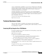
...specific CD and you are connected to -use tool for this platform, click Give Us Your Feedback. Cisco.com Cisco.com is a powerful, easy-to the Internet, click the pencil-and-paper icon in the world. Through Cisco.com, you display the document listing for doing business with Cisco. Obtaining Technical Assistance Cisco provides Cisco... anywhere in the toolbar to bug-doc@cisco.com. Click Submit to the Cisco documentation group. Customers and partners can find information about Cisco and our networking solutions, xviii Catalyst 2900 Series XL Hardware Installation Guide 78-6461...
...specific CD and you are connected to -use tool for this platform, click Give Us Your Feedback. Cisco.com Cisco.com is a powerful, easy-to the Internet, click the pencil-and-paper icon in the world. Through Cisco.com, you display the document listing for doing business with Cisco. Obtaining Technical Assistance Cisco provides Cisco... anywhere in the toolbar to bug-doc@cisco.com. Click Submit to the Cisco documentation group. Customers and partners can find information about Cisco and our networking solutions, xviii Catalyst 2900 Series XL Hardware Installation Guide 78-6461...
Hardware Installation Guide
Page 19
... who need information or assistance on Cisco.com to obtain additional personalized information and services. Registered users can resolve technical issues with Cisco. In each of an order, access technical support, and view benefits specific to their relationships with online technical support..., download and test software packages, and order Cisco learning materials and merchandise. To register for Cisco.com, go to the following website: http://www.cisco.com/register/ 78-6461-04 Catalyst 2900 Series XL...
... who need information or assistance on Cisco.com to obtain additional personalized information and services. Registered users can resolve technical issues with Cisco. In each of an order, access technical support, and view benefits specific to their relationships with online technical support..., download and test software packages, and order Cisco learning materials and merchandise. To register for Cisco.com, go to the following website: http://www.cisco.com/register/ 78-6461-04 Catalyst 2900 Series XL...

Hardware Installation Guide
Page 24
... such as CiscoWorks2000 LAN Management Suite (LMS) and HP OpenView. CMS is enhanced to monitor and control the switch and switch cluster members. Catalyst 2900 Series XL Hardware Installation Guide 1-4 78-6461-04 You can fully configure and monitor the...and monitor individual switches and switch clusters by using these front-panel components. You can manage the switch from an SNMP-compatible management station that is a graphical user interface that can be launched from the CLI. You can fully configure and monitor a standalone switch, a specific cluster member, or...
... such as CiscoWorks2000 LAN Management Suite (LMS) and HP OpenView. CMS is enhanced to monitor and control the switch and switch cluster members. Catalyst 2900 Series XL Hardware Installation Guide 1-4 78-6461-04 You can fully configure and monitor the...and monitor individual switches and switch clusters by using these front-panel components. You can manage the switch from an SNMP-compatible management station that is a graphical user interface that can be launched from the CLI. You can fully configure and monitor a standalone switch, a specific cluster member, or...

Hardware Installation Guide
Page 26
...can be explicitly set for more info on the Catalyst 2900 XL switches provide protocol support for the cables are described in any compatible network device up to 328 feet (100 meters) away: • 10BASE-T-compatible devices, such as workstations, Cisco IP Phones, and hubs through standard RJ-45 ... Phones-connected to the 10/100 port-must be connected to workstations, servers, routers, and Cisco IP Phones, be set to operate in Appendix B, "Connectors and Cable Specifications." These ports also can use a crossover cable. A port operating at 10BASE-T can be sure that both devices ...
...can be explicitly set for more info on the Catalyst 2900 XL switches provide protocol support for the cables are described in any compatible network device up to 328 feet (100 meters) away: • 10BASE-T-compatible devices, such as workstations, Cisco IP Phones, and hubs through standard RJ-45 ... Phones-connected to the 10/100 port-must be connected to workstations, servers, routers, and Cisco IP Phones, be set to operate in Appendix B, "Connectors and Cable Specifications." These ports also can use a crossover cable. A port operating at 10BASE-T can be sure that both devices ...

Hardware Installation Guide
Page 33
...(redundancy has been allocated to the appropriate switch documentation for redundant power system (RPS) descriptions specific for the switch. Pressing the Mode button on the Catalyst 2912 XL, 2924C XL, 2924 XL, 2924MF XL, 2924M XL, and 2924M XL DC Switches Color Off Green Blinking green Amber RPS ... connected but not functioning. • The RPS could have failed. For more information see the "Cisco RPS Connector" section on the Catalyst 2912 LRE XL and 2924 LRE XL Switches Color Off Solid green Blinking green RPS Status RPS is not installed. RPS is connected and ready...
...(redundancy has been allocated to the appropriate switch documentation for redundant power system (RPS) descriptions specific for the switch. Pressing the Mode button on the Catalyst 2912 XL, 2924C XL, 2924 XL, 2924MF XL, 2924M XL, and 2924M XL DC Switches Color Off Green Blinking green Amber RPS ... connected but not functioning. • The RPS could have failed. For more information see the "Cisco RPS Connector" section on the Catalyst 2912 LRE XL and 2924 LRE XL Switches Color Off Solid green Blinking green RPS Status RPS is not installed. RPS is connected and ready...

Hardware Installation Guide
Page 42
... might be damaged. If the supply voltage is not in the RPS documentation. Cisco RPS Connector Specific Cisco RPS models support specific Catalyst 2900 XL switches: • Cisco RPS 600 (model PWR600-AC-RPS)-supports the Catalyst 2912 XL, 2924C XL, 2924 XL, 2924MF XL, and 2924M XL switches. • Cisco RPS 300 (model PWR300-AC-RPS-N1)-supports the...
... might be damaged. If the supply voltage is not in the RPS documentation. Cisco RPS Connector Specific Cisco RPS models support specific Catalyst 2900 XL switches: • Cisco RPS 600 (model PWR600-AC-RPS)-supports the Catalyst 2912 XL, 2924C XL, 2924 XL, 2924MF XL, and 2924M XL switches. • Cisco RPS 300 (model PWR300-AC-RPS-N1)-supports the...

Hardware Installation Guide
Page 51
Rear-panel power connector is within the ranges listed in Appendix A, "Technical Specifications." • Airflow around the switch and through the vents is unrestricted. • Temperature around it might be easily read. - Your Catalyst 2900 XL switch is missing or damaged, contact your Cisco representative or reseller for support. Return all packing materials to ports is...
Rear-panel power connector is within the ranges listed in Appendix A, "Technical Specifications." • Airflow around the switch and through the vents is unrestricted. • Temperature around it might be easily read. - Your Catalyst 2900 XL switch is missing or damaged, contact your Cisco representative or reseller for support. Return all packing materials to ports is...

Hardware Installation Guide
Page 79
...-TX devices: Step 1 When connecting to workstations, servers, routers, and Cisco IP Phones, connect a straight-through Category 5 cable to switches or repeaters, use a crossover Category 5 cable. When connecting to an ... you can explicitly set can reduce performance or result in the "Cable and Adapter Specifications" section on both ends of the connection. Pinouts for configuring the 10/100 Ethernet ... • Set the port speed and duplex parameters on page B-4. 78-6461-04 Catalyst 2900 Series XL Hardware Installation Guide 2-35 Connecting devices that have their speed and duplex...
...-TX devices: Step 1 When connecting to workstations, servers, routers, and Cisco IP Phones, connect a straight-through Category 5 cable to switches or repeaters, use a crossover Category 5 cable. When connecting to an ... you can explicitly set can reduce performance or result in the "Cable and Adapter Specifications" section on both ends of the connection. Pinouts for configuring the 10/100 Ethernet ... • Set the port speed and duplex parameters on page B-4. 78-6461-04 Catalyst 2900 Series XL Hardware Installation Guide 2-35 Connecting devices that have their speed and duplex...

Hardware Installation Guide
Page 86
... Cisco. or terminal-emulation software to a terminal. Connecting to a Module Port Chapter 2 Installation Connecting to a Module Port For information about installing and connecting to modules in the Catalyst 2924M XL and 2912MF XL module slots, refer to the switch console port. For console port and adapter pinout information, see the "Cable and Adapter Specifications...
... Cisco. or terminal-emulation software to a terminal. Connecting to a Module Port Chapter 2 Installation Connecting to a Module Port For information about installing and connecting to modules in the Catalyst 2924M XL and 2912MF XL module slots, refer to the switch console port. For console port and adapter pinout information, see the "Cable and Adapter Specifications...

Hardware Installation Guide
Page 99
A A P P E N D I X Technical Specifications Table A-1, Table A-2, Table A-3, and Table A-5 list the technical specifications for additional specifications. For switches that support modules (Catalyst 2912MF XL and 2924M XL), also refer to the Catalyst 2900 Series XL Modules Installation Guide and the Catalyst 2900 Series XL ATM Modules Installation Guide for the Catalyst 2900 series switches. Table A-6 lists the agency approvals for EMI and safety. 78-6461-04 Catalyst 2900 Series XL Hardware Installation Guide A-1
A A P P E N D I X Technical Specifications Table A-1, Table A-2, Table A-3, and Table A-5 list the technical specifications for additional specifications. For switches that support modules (Catalyst 2912MF XL and 2924M XL), also refer to the Catalyst 2900 Series XL Modules Installation Guide and the Catalyst 2900 Series XL ATM Modules Installation Guide for the Catalyst 2900 series switches. Table A-6 lists the agency approvals for EMI and safety. 78-6461-04 Catalyst 2900 Series XL Hardware Installation Guide A-1
Hardware Installation Guide
Page 100
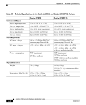
Appendix A Technical Specifications Table A-1 Technical Specifications for the Catalyst 2912 XL and Catalyst 2912MF XL Switches Environmental Ranges Operating temperature Storage temperature Operating humidity Operating altitude Storage altitude Power Requirements AC input voltage DC input voltages Catalyst 2912 XL 32 to 113°F (0 to 45°C) -4 ...(maximum) 239 Btus per hour 7 lb (3.2 kg) Dimensions (H x W x D) 1.73 x 17.5 x 9.79 in. (4.4 x 44.5 x 24.8 cm) Catalyst 2912MF XL 32 to 113°F (0 to 45°C) -4 to 149°F (-10 to 65°C) 10 to 85% (noncondensing) Up to 10,000 ft...
Appendix A Technical Specifications Table A-1 Technical Specifications for the Catalyst 2912 XL and Catalyst 2912MF XL Switches Environmental Ranges Operating temperature Storage temperature Operating humidity Operating altitude Storage altitude Power Requirements AC input voltage DC input voltages Catalyst 2912 XL 32 to 113°F (0 to 45°C) -4 ...(maximum) 239 Btus per hour 7 lb (3.2 kg) Dimensions (H x W x D) 1.73 x 17.5 x 9.79 in. (4.4 x 44.5 x 24.8 cm) Catalyst 2912MF XL 32 to 113°F (0 to 45°C) -4 to 149°F (-10 to 65°C) 10 to 85% (noncondensing) Up to 10,000 ft...

Hardware Installation Guide
Page 101
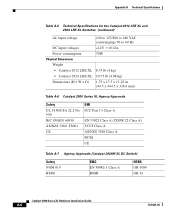
Appendix A Technical Specifications Table A-2 Technical Specifications for the Catalyst 2924 XL and Catalyst 2924C XL Switches Catalyst 2924 XL Environmental Operating Ranges Operating temperature 32 to 113°F (0 to 45°C) Storage temperature -4 to 149°F (-10 to 65°C) Operating ... m) AC input voltage DC input voltages 100 to 127/200 to 240 VAC (autoranging) 50 to -14 dBm 78-6461-04 Catalyst 2900 Series XL Hardware Installation Guide A-3 dBm = decibel milliwatt Catalyst 2924C XL 32 to 113°F (0 to 45°C) -4 to 149°F (-10 to 65°C) 10 to 85% ...
Appendix A Technical Specifications Table A-2 Technical Specifications for the Catalyst 2924 XL and Catalyst 2924C XL Switches Catalyst 2924 XL Environmental Operating Ranges Operating temperature 32 to 113°F (0 to 45°C) Storage temperature -4 to 149°F (-10 to 65°C) Operating ... m) AC input voltage DC input voltages 100 to 127/200 to 240 VAC (autoranging) 50 to -14 dBm 78-6461-04 Catalyst 2900 Series XL Hardware Installation Guide A-3 dBm = decibel milliwatt Catalyst 2924C XL 32 to 113°F (0 to 45°C) -4 to 149°F (-10 to 65°C) 10 to 85% ...
Hardware Installation Guide
Page 102
Appendix A Technical Specifications Table A-3 Technical Specifications for the Catalyst 2924M XL Switches Environmental Operating Ranges Operating temperature 32 to 113°F (0 to 45°C) Storage temperature -4 to 149°F (-10 to 65°C) Operating humidity 10 to ... Btus per hour Physical Dimensions Weight 13.5 lb (6.12 kg) 15 lb (6.8 kg) with two modules installed Dimensions (H x W x D) 3.46 x 17.5 x 12 in. (8.8 x 44.5 x 30.5 cm) Catalyst 2900 Series XL Hardware Installation Guide A-4 78-6461-04
Appendix A Technical Specifications Table A-3 Technical Specifications for the Catalyst 2924M XL Switches Environmental Operating Ranges Operating temperature 32 to 113°F (0 to 45°C) Storage temperature -4 to 149°F (-10 to 65°C) Operating humidity 10 to ... Btus per hour Physical Dimensions Weight 13.5 lb (6.12 kg) 15 lb (6.8 kg) with two modules installed Dimensions (H x W x D) 3.46 x 17.5 x 12 in. (8.8 x 44.5 x 30.5 cm) Catalyst 2900 Series XL Hardware Installation Guide A-4 78-6461-04
Hardware Installation Guide
Page 103
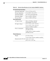
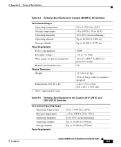
...,000 ft (3000 m) Up to 15,000 ft (4570 m) 100W -36 to 15,000 ft (4570 m) Catalyst 2900 Series XL Hardware Installation Guide A-5 Appendix A Technical Specifications 78-6461-04 Table A-4 Technical Specifications for Catalyst 2924M XL DC Switches Environmental Ranges Operating temperature Storage temperature Operating humidity Operating altitude Storage altitude Power Requirements Power consumption DC...
...,000 ft (3000 m) Up to 15,000 ft (4570 m) 100W -36 to 15,000 ft (4570 m) Catalyst 2900 Series XL Hardware Installation Guide A-5 Appendix A Technical Specifications 78-6461-04 Table A-4 Technical Specifications for Catalyst 2924M XL DC Switches Environmental Ranges Operating temperature Storage temperature Operating humidity Operating altitude Storage altitude Power Requirements Power consumption DC...
Hardware Installation Guide
Page 104
... A Technical Specifications Table A-5 Technical Specifications for the Catalyst 2912 LRE XL and 2924 LRE XL Switches (continued) AC input voltage 100 to 127/200 to 240 VAC (autoranging) 50 to 60 Hz DC input voltages +12V @12A Power consumption 70W Physical Dimensions Weight • Catalyst 2912 LRE XL 8.75 lb (4 kg) • Catalyst 2924 LRE XL..., TS001 CE EMI FCC Part 15 Class A EN 55022 Class A (CISPR 22 Class A) VCCI Class A AS/NZS 3548 Class A BCIQ CE Table A-7 Agency Approvals (Catalyst 2924M XL DC Switch) Safety NOM 019 BSMI EMC EN 50082-1 Class A BSMI NEBS GR-1089 GR-63...
... A Technical Specifications Table A-5 Technical Specifications for the Catalyst 2912 LRE XL and 2924 LRE XL Switches (continued) AC input voltage 100 to 127/200 to 240 VAC (autoranging) 50 to 60 Hz DC input voltages +12V @12A Power consumption 70W Physical Dimensions Weight • Catalyst 2912 LRE XL 8.75 lb (4 kg) • Catalyst 2924 LRE XL..., TS001 CE EMI FCC Part 15 Class A EN 55022 Class A (CISPR 22 Class A) VCCI Class A AS/NZS 3548 Class A BCIQ CE Table A-7 Agency Approvals (Catalyst 2924M XL DC Switch) Safety NOM 019 BSMI EMC EN 50082-1 Class A BSMI NEBS GR-1089 GR-63...