
Hardware Installation Guide
Page 6
... DC Power Connector 1-21 Cisco RPS Connector 1-22 Console Port 1-23 2 C H A P T E R Installation 2-1 Preparing for Installation 2-1 Warnings 2-1 EMC Regulatory Statements 2-4 U.S.A. 2-4 Taiwan 2-4 Japan 2-5 Korea 2-5 Hungary 2-6 Installation Guidelines 2-6 Verifying Package Contents 2-7 Installing the Switch on a Table or Shelf 2-9 Installing the Switch in a Rack 2-9 Removing Screws from the Switch 2-11 Attaching the Brackets to a Catalyst 2912 XL, 2924C XL...
... DC Power Connector 1-21 Cisco RPS Connector 1-22 Console Port 1-23 2 C H A P T E R Installation 2-1 Preparing for Installation 2-1 Warnings 2-1 EMC Regulatory Statements 2-4 U.S.A. 2-4 Taiwan 2-4 Japan 2-5 Korea 2-5 Hungary 2-6 Installation Guidelines 2-6 Verifying Package Contents 2-7 Installing the Switch on a Table or Shelf 2-9 Installing the Switch in a Rack 2-9 Removing Screws from the Switch 2-11 Attaching the Brackets to a Catalyst 2912 XL, 2924C XL...

Hardware Installation Guide
Page 7
...18 Attaching the Optional Cable Guide 2-19 Installing the Switch on a Wall 2-20 Attaching the Brackets to the Switch 2-21 Mounting the Switch to a Wall 2-22 Powering On the Switch and Running POST 2-24 Connecting to DC Power 2-25 Preparing for Installation 2-25 Grounding the Switch 2-26 Wiring the DC-Input Power Source 2-29... Correcting Module POST Failures 3-2 Diagnosing Problems 3-3 Technical Specifications A-1 Connectors and Cable Specifications B-1 Connector Specifications B-1 10/100 Ports B-1 100BASE-FX Ports B-2 Contents 78-6461-04 Catalyst 2900 Series XL Hardware Installation Guide vii
...18 Attaching the Optional Cable Guide 2-19 Installing the Switch on a Wall 2-20 Attaching the Brackets to the Switch 2-21 Mounting the Switch to a Wall 2-22 Powering On the Switch and Running POST 2-24 Connecting to DC Power 2-25 Preparing for Installation 2-25 Grounding the Switch 2-26 Wiring the DC-Input Power Source 2-29... Correcting Module POST Failures 3-2 Diagnosing Problems 3-3 Technical Specifications A-1 Connectors and Cable Specifications B-1 Connector Specifications B-1 10/100 Ports B-1 100BASE-FX Ports B-2 Contents 78-6461-04 Catalyst 2900 Series XL Hardware Installation Guide vii

Hardware Installation Guide
Page 9
INDEX Class 1 Laser Product Warning C-22 Laser Beam Exposure Warning C-23 No On/Off Switch Warning C-24 Chassis Warning-Rack-Mounting and Servicing C-25 Reinforced Insulation Warning C-29 LAN Connections Only Warning C-30 No Field-Replaceable Units Warning C-31 Installation ... Equipment Warning C-36 Ground Connection Warning C-37 Qualified Personnel Warning C-38 DC Power Disconnection Warning C-39 Exposed Wire Lead Warning C-41 Contents 78-6461-04 Catalyst 2900 Series XL Hardware Installation Guide ix
INDEX Class 1 Laser Product Warning C-22 Laser Beam Exposure Warning C-23 No On/Off Switch Warning C-24 Chassis Warning-Rack-Mounting and Servicing C-25 Reinforced Insulation Warning C-29 LAN Connections Only Warning C-30 No Field-Replaceable Units Warning C-31 Installation ... Equipment Warning C-36 Ground Connection Warning C-37 Qualified Personnel Warning C-38 DC Power Disconnection Warning C-39 Exposed Wire Lead Warning C-41 Contents 78-6461-04 Catalyst 2900 Series XL Hardware Installation Guide ix

Hardware Installation Guide
Page 11
... Installation Guide xi It describes the physical and performance characteristics of Catalyst 2900 series XL switches. Chapter 2, "Installation," provides the procedures for installing and configuring a Catalyst 2900 series XL switch. Organization This guide is for the networking or computer technician responsible for installing a switch in a rack, on a desk, or on a wall. Chapter 3, "Troubleshooting," describes how...
... Installation Guide xi It describes the physical and performance characteristics of Catalyst 2900 series XL switches. Chapter 2, "Installation," provides the procedures for installing and configuring a Catalyst 2900 series XL switch. Organization This guide is for the networking or computer technician responsible for installing a switch in a rack, on a desk, or on a wall. Chapter 3, "Troubleshooting," describes how...

Hardware Installation Guide
Page 12
...these conventions: • Commands and keywords are in boldface. • Arguments for the switches and the regulatory agency approvals. Notes contain helpful suggestions or references to the switch. Caution Means reader be used to connect to materials not contained in this manual. ...Conventions Preface Appendix A, "Technical Specifications," lists the physical and environmental specifications for which you supply values are in this guide. Catalyst 2900 Series XL...
...these conventions: • Commands and keywords are in boldface. • Arguments for the switches and the regulatory agency approvals. Notes contain helpful suggestions or references to the switch. Caution Means reader be used to connect to materials not contained in this manual. ...Conventions Preface Appendix A, "Technical Specifications," lists the physical and environmental specifications for which you supply values are in this guide. Catalyst 2900 Series XL...

Hardware Installation Guide
Page 15
... only in the "Obtaining Documentation" section on page xvi. • Release Notes for the Catalyst 2900 Series XL and Catalyst 3500 Series XL Switches (not orderable but is available on Cisco.com for the latest information. 78-6461-04 Catalyst 2900 Series XL Hardware Installation Guide xv Se förklaringar av de varningar som fö...
... only in the "Obtaining Documentation" section on page xvi. • Release Notes for the Catalyst 2900 Series XL and Catalyst 3500 Series XL Switches (not orderable but is available on Cisco.com for the latest information. 78-6461-04 Catalyst 2900 Series XL Hardware Installation Guide xv Se förklaringar av de varningar som fö...

Hardware Installation Guide
Page 16
... online help (available only from the switch CMS software) • Catalyst 2900 Series XL Hardware Installation Guide (order number DOC-786461=) • Catalyst 3500 Series XL Hardware Installation Guide (order number DOC-786456=) • Catalyst 2900 Series XL Modules Installation Guide (order...1000BASE-T Gigabit Interface Converter Installation Note (not orderable but is available on Cisco.com) • Catalyst GigaStack Gigabit Interface Converter Hardware Installation Guide (order number DOC-786460=) • Cisco LRE CPE Hardware Installation Guide (order number DOC-7811469=) • ...
... online help (available only from the switch CMS software) • Catalyst 2900 Series XL Hardware Installation Guide (order number DOC-786461=) • Catalyst 3500 Series XL Hardware Installation Guide (order number DOC-786456=) • Catalyst 2900 Series XL Modules Installation Guide (order...1000BASE-T Gigabit Interface Converter Installation Note (not orderable but is available on Cisco.com) • Catalyst GigaStack Gigabit Interface Converter Hardware Installation Guide (order number DOC-786460=) • Cisco LRE CPE Hardware Installation Guide (order number DOC-7811469=) • ...

Hardware Installation Guide
Page 21
...shared memory, and then forwards the packet to the destination port 78-6461-04 Catalyst 2900 Series XL Hardware Installation Guide 1-1 The Catalyst 2900 XL switches have these topics that allows an Ethernet network to reach distances up to which ...Catalyst 2900 series XL switches, hereafter referred to as the switches. • Switch features, including management options • Descriptions of the front and rear panels • Descriptions of the LEDs Features The switches are stackable 10/100 Ethernet switches to 4921 feet (1500 meters). The switches can connect workstations, Cisco...
...shared memory, and then forwards the packet to the destination port 78-6461-04 Catalyst 2900 Series XL Hardware Installation Guide 1-1 The Catalyst 2900 XL switches have these topics that allows an Ethernet network to reach distances up to which ...Catalyst 2900 series XL switches, hereafter referred to as the switches. • Switch features, including management options • Descriptions of the front and rear panels • Descriptions of the LEDs Features The switches are stackable 10/100 Ethernet switches to 4921 feet (1500 meters). The switches can connect workstations, Cisco...

Hardware Installation Guide
Page 22
... • On the Catalyst 2912 LRE XL and 2924 LRE XL switches, up to 24 LRE ports through one RJ-21 connector and hot swapping capability with the Cisco LRE customer premises equipment (CPE) devices • Supports up to 2048 MAC addresses on the Catalyst 2924 XL, 2924C XL..., and 2912 XL switches • Supports up to 8192 MAC addresses on the Catalyst 2924M XL, Catalyst 2924M XL DC and Catalyst 2912MF XL switches Figure 1-1 shows the switch models. Catalyst ...
... • On the Catalyst 2912 LRE XL and 2924 LRE XL switches, up to 24 LRE ports through one RJ-21 connector and hot swapping capability with the Cisco LRE customer premises equipment (CPE) devices • Supports up to 2048 MAC addresses on the Catalyst 2924 XL, 2924C XL..., and 2912 XL switches • Supports up to 8192 MAC addresses on the Catalyst 2924M XL, Catalyst 2924M XL DC and Catalyst 2912MF XL switches Figure 1-1 shows the switch models. Catalyst ...

Hardware Installation Guide
Page 23
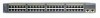
Chapter 1 Product Overview Figure 1-1 Catalyst 2900 Series XL Switches Version Number Description WS-C2912-LRE-XL 4 fixed autosensing 10/100 ports INPUT OUTPUT PWR PWR RESET TEMP FAN 9X 10X 11X 12X 12 LRE ports Cisco RPS 300 WS-C2924-LRE-XL 4 fixed autosensing 10/100 ports 24 LRE ports INPUT OUTPUT PWR PWR... 4 5 100BASE-FX 6 7 8 9 10 11 12 WS-C2924M-XL WS-C2924M-XLEM-DC 24 fixed autosensing 10/100 ports 2 expansion slots 12 MODE 1X 2X 3X Catalyst 2900 SERIES XL 4X 5X 6X 7X 8X 9X 10X 11X 100BaseFX 12X 13X 14X 15X 16X 17X 18X 19X 20X 21X 22X 23X 24X...
Chapter 1 Product Overview Figure 1-1 Catalyst 2900 Series XL Switches Version Number Description WS-C2912-LRE-XL 4 fixed autosensing 10/100 ports INPUT OUTPUT PWR PWR RESET TEMP FAN 9X 10X 11X 12X 12 LRE ports Cisco RPS 300 WS-C2924-LRE-XL 4 fixed autosensing 10/100 ports 24 LRE ports INPUT OUTPUT PWR PWR... 4 5 100BASE-FX 6 7 8 9 10 11 12 WS-C2924M-XL WS-C2924M-XLEM-DC 24 fixed autosensing 10/100 ports 2 expansion slots 12 MODE 1X 2X 3X Catalyst 2900 SERIES XL 4X 5X 6X 7X 8X 9X 10X 11X 100BaseFX 12X 13X 14X 15X 16X 17X 18X 19X 20X 21X 22X 23X 24X...

Hardware Installation Guide
Page 24
...port-level settings. • Command-line Interface (CLI)-The switch IOS CLI software is enhanced to the Catalyst 2900 Series XL and Catalyst 3500 Series XL Software Configuration Guide. You can manage the switch from an SNMP-compatible management station that can be launched from... groups. For more information about CMS, the CLI, and SNMP refer to support desktop-switching features. Catalyst 2900 Series XL Hardware Installation Guide 1-4 78-6461-04 You can manage switch configuration settings, performance, security, and collect statistics by using Telnet from the CLI. You ...
...port-level settings. • Command-line Interface (CLI)-The switch IOS CLI software is enhanced to the Catalyst 2900 Series XL and Catalyst 3500 Series XL Software Configuration Guide. You can manage the switch from an SNMP-compatible management station that can be launched from... groups. For more information about CMS, the CLI, and SNMP refer to support desktop-switching features. Catalyst 2900 Series XL Hardware Installation Guide 1-4 78-6461-04 You can manage switch configuration settings, performance, security, and collect statistics by using Telnet from the CLI. You ...

Hardware Installation Guide
Page 26
... device supports it) and configures itself accordingly. Unlike the 3524-PWR XL switch, the Catalyst 2900 XL switches do not provide inline power. For more information about these features. Pinouts for Cisco IP Phones and per-port priority override. When connecting the switch to switches or hubs, use Category 3 and 4 cables. The 10/100 ports on...
... device supports it) and configures itself accordingly. Unlike the 3524-PWR XL switch, the Catalyst 2900 XL switches do not provide inline power. For more information about these features. Pinouts for Cisco IP Phones and per-port priority override. When connecting the switch to switches or hubs, use Category 3 and 4 cables. The 10/100 ports on...

Hardware Installation Guide
Page 27
... connected through a private branch exchange (PBX) switch, a Cisco LRE 48 POTS Splitter can be up to 6562 feet (2 kilometers). The link between the switch and the attached device can be over distances of up to private telephone networks and the public system telephone network 78-6461-04 Catalyst 2900 Series XL Hardware Installation Guide...
... connected through a private branch exchange (PBX) switch, a Cisco LRE 48 POTS Splitter can be up to 6562 feet (2 kilometers). The link between the switch and the attached device can be over distances of up to private telephone networks and the public system telephone network 78-6461-04 Catalyst 2900 Series XL Hardware Installation Guide...

Hardware Installation Guide
Page 28
...Number WS-X2914-XL WS-X2914-XL-V WS-X2922-XL WS-X2922-XL-V WS-X2924-XL-V Catalyst 2900 Series XL Hardware Installation Guide 1-8 78-6461-04 Digital telephones connected to digital PBX switches that use frequencies above 700 kHz. [CSCdu73260] If the installation does not have a PBX, a... of digital PBX switches, some digital PBX switch services use the 0 to the PSTN. Module Slots The module slots (see Figure 1-2) are designed to the Installation Notes for the Catalyst 2900 XL hot-swappable modules. Note Cisco Long-Reach Ethernet (LRE) products are for the Cisco LRE 48 POTS Splitter...
...Number WS-X2914-XL WS-X2914-XL-V WS-X2922-XL WS-X2922-XL-V WS-X2924-XL-V Catalyst 2900 Series XL Hardware Installation Guide 1-8 78-6461-04 Digital telephones connected to digital PBX switches that use frequencies above 700 kHz. [CSCdu73260] If the installation does not have a PBX, a... of digital PBX switches, some digital PBX switch services use the 0 to the PSTN. Module Slots The module slots (see Figure 1-2) are designed to the Installation Notes for the Catalyst 2900 XL hot-swappable modules. Note Cisco Long-Reach Ethernet (LRE) products are for the Cisco LRE 48 POTS Splitter...

Hardware Installation Guide
Page 29
... on self-test (POST) verifies that the module is reduced to the Release Notes for Catalyst 2900 series XL switches. A power-on expansion modules for the Catalyst 2900 Series XL and Catalyst 3500 Series XL Switches. You can use to select a port mode. Figure 1-5, Figure 1-6, and Figure 1-7... show the location of the LEDs and the Mode button that switch. Catalyst 2900 Series XL Hardware Installation Guide 1-9 Chapter 1 Product Overview Front-Panel Description Table 1-1 Expansion Modules (continued) Module Type Model Number...
... on self-test (POST) verifies that the module is reduced to the Release Notes for Catalyst 2900 series XL switches. A power-on expansion modules for the Catalyst 2900 Series XL and Catalyst 3500 Series XL Switches. You can use to select a port mode. Figure 1-5, Figure 1-6, and Figure 1-7... show the location of the LEDs and the Mode button that switch. Catalyst 2900 Series XL Hardware Installation Guide 1-9 Chapter 1 Product Overview Front-Panel Description Table 1-1 Expansion Modules (continued) Module Type Model Number...

Hardware Installation Guide
Page 30
... the utilization meter (UTL) are visible on the Cluster Management Suite (CMS) window and, if the switch is a cluster member, on the CMS Cluster Manager window. The Catalyst 2900 Series XL and Catalyst 3500 Series XL Software Configuration Guide describes how to use CMS to manage standalone or individual... switches and how to use cluster management software to manage switch clusters]. Figure 1-5 Catalyst 2912 XL, 2924 XL, and 2924C XL LEDs 10/100 port LEDs System LED Port mode LEDs MODE 1X 2X...
... the utilization meter (UTL) are visible on the Cluster Management Suite (CMS) window and, if the switch is a cluster member, on the CMS Cluster Manager window. The Catalyst 2900 Series XL and Catalyst 3500 Series XL Software Configuration Guide describes how to use CMS to manage standalone or individual... switches and how to use cluster management software to manage switch clusters]. Figure 1-5 Catalyst 2912 XL, 2924 XL, and 2924C XL LEDs 10/100 port LEDs System LED Port mode LEDs MODE 1X 2X...

Hardware Installation Guide
Page 32
... Status System is operating normally. For information on the System LED colors during POST, see the "Powering On the Switch and Running POST" section on page 2-24. 1-12 Catalyst 2900 Series XL Hardware Installation Guide 78-6461-04 System is not powered up. System is receiving power but is... receiving power and functioning properly. Front-Panel Description Figure 1-7 Catalyst 2912 LRE XL and 2924 LRE XL LEDs 10/100 port LEDs Chapter 1 Product Overview SYSTEM RPS MODE LRE STAT DUPLX SPEED Mode button...
... Status System is operating normally. For information on the System LED colors during POST, see the "Powering On the Switch and Running POST" section on page 2-24. 1-12 Catalyst 2900 Series XL Hardware Installation Guide 78-6461-04 System is not powered up. System is receiving power but is... receiving power and functioning properly. Front-Panel Description Figure 1-7 Catalyst 2912 LRE XL and 2924 LRE XL LEDs 10/100 port LEDs Chapter 1 Product Overview SYSTEM RPS MODE LRE STAT DUPLX SPEED Mode button...

Hardware Installation Guide
Page 33
.... Table 1-3 RPS LED on the Catalyst 2912 XL, 2924C XL, 2924 XL, 2924MF XL, 2924M XL, and 2924M XL DC Switches Color Off Green Blinking green Amber RPS Status RPS is unavailable because it restarts. For more information see the "Cisco RPS Connector" section on the RPS ...not functioning. • The RPS could have failed. • The fan in standby mode. RPS is not a recommended configuration. All other Catalyst 2900 XL and Catalyst 3500 XL switches use the Cisco RPS 300 (model PWR300-AC-RPS-N1). Chapter 1 Product Overview Front-Panel Description RPS LED The...
.... Table 1-3 RPS LED on the Catalyst 2912 XL, 2924C XL, 2924 XL, 2924MF XL, 2924M XL, and 2924M XL DC Switches Color Off Green Blinking green Amber RPS Status RPS is unavailable because it restarts. For more information see the "Cisco RPS Connector" section on the RPS ...not functioning. • The RPS could have failed. • The fan in standby mode. RPS is not a recommended configuration. All other Catalyst 2900 XL and Catalyst 3500 XL switches use the Cisco RPS 300 (model PWR300-AC-RPS-N1). Chapter 1 Product Overview Front-Panel Description RPS LED The...

Hardware Installation Guide
Page 34
...Table 1-6 and Table 1-7 list the port LED colors. Front-Panel Description Chapter 1 Product Overview Table 1-3 RPS LED on the Catalyst 2912 LRE XL and 2924 LRE XL Switches (continued) Color Solid amber Blinking amber RPS Status The RPS is the default mode. Table 1-4 Port Mode LEDs on the RPS... Cisco Systems. The internal power supply in use by the switch. (See Figure 1-8.) The port duplex mode: full duplex or half duplex, and default modes: • 10/100 ports: auto • 100BaseFX ports: auto • Gigabit ports: auto The port operating speed: 10 or 100 Mbps. 1-14 Catalyst 2900...
...Table 1-6 and Table 1-7 list the port LED colors. Front-Panel Description Chapter 1 Product Overview Table 1-3 RPS LED on the Catalyst 2912 LRE XL and 2924 LRE XL Switches (continued) Color Solid amber Blinking amber RPS Status The RPS is the default mode. Table 1-4 Port Mode LEDs on the RPS... Cisco Systems. The internal power supply in use by the switch. (See Figure 1-8.) The port duplex mode: full duplex or half duplex, and default modes: • 10/100 ports: auto • 100BaseFX ports: auto • Gigabit ports: auto The port operating speed: 10 or 100 Mbps. 1-14 Catalyst 2900...

Hardware Installation Guide
Page 35
... Note When the LRE mode is active, the 10/100 switch ports on the remote CPE. Ethernet link status of the LRE ports on all Catalyst 2900 XL and Catalyst 3500 XL switches except the Catalyst 2912 LRE XL and Catalyst 2924 LRE XL switches. The port duplex mode: full duplex or half duplex. ...Chapter 1 Product Overview Front-Panel Description Table 1-5 Port Mode LEDs on Catalyst 2912 LRE XL and 2924 LRE XL Switches Mode LED LRE STAT DUPLX SPEED Port Mode LRE link status Port status Port duplex mode Port speed Description Long-Reach ...
... Note When the LRE mode is active, the 10/100 switch ports on the remote CPE. Ethernet link status of the LRE ports on all Catalyst 2900 XL and Catalyst 3500 XL switches except the Catalyst 2912 LRE XL and Catalyst 2924 LRE XL switches. The port duplex mode: full duplex or half duplex. ...Chapter 1 Product Overview Front-Panel Description Table 1-5 Port Mode LEDs on Catalyst 2912 LRE XL and 2924 LRE XL Switches Mode LED LRE STAT DUPLX SPEED Port Mode LRE link status Port status Port duplex mode Port speed Description Long-Reach ...


