
Hardware Installation Guide
Page 6
... DC Power Connector 1-21 Cisco RPS Connector 1-22 Console Port 1-23 2 C H A P T E R Installation 2-1 Preparing for Installation 2-1 Warnings 2-1 EMC Regulatory Statements 2-4 U.S.A. 2-4 Taiwan 2-4 Japan 2-5 Korea 2-5 Hungary 2-6 Installation Guidelines 2-6 Verifying Package Contents 2-7 Installing the Switch on a Table or Shelf 2-9 Installing the Switch in a Rack 2-9 Removing Screws from the Switch 2-11 Attaching the Brackets to a Catalyst 2912 XL, 2924C XL...
... DC Power Connector 1-21 Cisco RPS Connector 1-22 Console Port 1-23 2 C H A P T E R Installation 2-1 Preparing for Installation 2-1 Warnings 2-1 EMC Regulatory Statements 2-4 U.S.A. 2-4 Taiwan 2-4 Japan 2-5 Korea 2-5 Hungary 2-6 Installation Guidelines 2-6 Verifying Package Contents 2-7 Installing the Switch on a Table or Shelf 2-9 Installing the Switch in a Rack 2-9 Removing Screws from the Switch 2-11 Attaching the Brackets to a Catalyst 2912 XL, 2924C XL...

Hardware Installation Guide
Page 7
...18 Attaching the Optional Cable Guide 2-19 Installing the Switch on a Wall 2-20 Attaching the Brackets to the Switch 2-21 Mounting the Switch to a Wall 2-22 Powering On the Switch and Running POST 2-24 Connecting to DC Power 2-25 Preparing for Installation 2-25 Grounding the Switch 2-26 Wiring the DC-Input Power Source 2-29... Correcting Module POST Failures 3-2 Diagnosing Problems 3-3 Technical Specifications A-1 Connectors and Cable Specifications B-1 Connector Specifications B-1 10/100 Ports B-1 100BASE-FX Ports B-2 Contents 78-6461-04 Catalyst 2900 Series XL Hardware Installation Guide vii
...18 Attaching the Optional Cable Guide 2-19 Installing the Switch on a Wall 2-20 Attaching the Brackets to the Switch 2-21 Mounting the Switch to a Wall 2-22 Powering On the Switch and Running POST 2-24 Connecting to DC Power 2-25 Preparing for Installation 2-25 Grounding the Switch 2-26 Wiring the DC-Input Power Source 2-29... Correcting Module POST Failures 3-2 Diagnosing Problems 3-3 Technical Specifications A-1 Connectors and Cable Specifications B-1 Connector Specifications B-1 10/100 Ports B-1 100BASE-FX Ports B-2 Contents 78-6461-04 Catalyst 2900 Series XL Hardware Installation Guide vii

Hardware Installation Guide
Page 9
INDEX Class 1 Laser Product Warning C-22 Laser Beam Exposure Warning C-23 No On/Off Switch Warning C-24 Chassis Warning-Rack-Mounting and Servicing C-25 Reinforced Insulation Warning C-29 LAN Connections Only Warning C-30 No Field-Replaceable Units Warning C-31 Installation ... Equipment Warning C-36 Ground Connection Warning C-37 Qualified Personnel Warning C-38 DC Power Disconnection Warning C-39 Exposed Wire Lead Warning C-41 Contents 78-6461-04 Catalyst 2900 Series XL Hardware Installation Guide ix
INDEX Class 1 Laser Product Warning C-22 Laser Beam Exposure Warning C-23 No On/Off Switch Warning C-24 Chassis Warning-Rack-Mounting and Servicing C-25 Reinforced Insulation Warning C-29 LAN Connections Only Warning C-30 No Field-Replaceable Units Warning C-31 Installation ... Equipment Warning C-36 Ground Connection Warning C-37 Qualified Personnel Warning C-38 DC Power Disconnection Warning C-39 Exposed Wire Lead Warning C-41 Contents 78-6461-04 Catalyst 2900 Series XL Hardware Installation Guide ix

Hardware Installation Guide
Page 11
... that you are familiar with the concepts and terminology of Catalyst 2900 series XL switches. Chapter 2, "Installation," provides the procedures for installing and configuring a Catalyst 2900 series XL switch. Preface Audience This guide is organized into the following chapters: Chapter 1, "Product Overview," summarizes the switch features and describes the ports, the standards they support, and...
... that you are familiar with the concepts and terminology of Catalyst 2900 series XL switches. Chapter 2, "Installation," provides the procedures for installing and configuring a Catalyst 2900 series XL switch. Preface Audience This guide is organized into the following chapters: Chapter 1, "Product Overview," summarizes the switch features and describes the ports, the standards they support, and...

Hardware Installation Guide
Page 12
... the regulatory agency approvals. Notes contain helpful suggestions or references to the switch. In this guide. Appendix B, "Connectors and Cable Specifications," describes the connectors, cables, and adapters that could result in angle brackets (< >). Catalyst 2900 Series XL Hardware Installation Guide xii 78-6461-04 Appendix C, "Translated Safety Warnings," provides translations in various...
... the regulatory agency approvals. Notes contain helpful suggestions or references to the switch. In this guide. Appendix B, "Connectors and Cable Specifications," describes the connectors, cables, and adapters that could result in angle brackets (< >). Catalyst 2900 Series XL Hardware Installation Guide xii 78-6461-04 Appendix C, "Translated Safety Warnings," provides translations in various...

Hardware Installation Guide
Page 15
... xvi. • Release Notes for the Catalyst 2900 Series XL and Catalyst 3500 Series XL Switches (not orderable but is available on Cisco.com) Note Switch requirements and procedures for initial configurations and software upgrades tend to the release notes on Cisco.com for the latest information. 78-6461-04 Catalyst 2900 Series XL Hardware Installation Guide...
... xvi. • Release Notes for the Catalyst 2900 Series XL and Catalyst 3500 Series XL Switches (not orderable but is available on Cisco.com) Note Switch requirements and procedures for initial configurations and software upgrades tend to the release notes on Cisco.com for the latest information. 78-6461-04 Catalyst 2900 Series XL Hardware Installation Guide...

Hardware Installation Guide
Page 16
... online help (available only from the switch CMS software) • Catalyst 2900 Series XL Hardware Installation Guide (order number DOC-786461=) • Catalyst 3500 Series XL Hardware Installation Guide (order number DOC-786456=) • Catalyst 2900 Series XL Modules Installation Guide (order...1000BASE-T Gigabit Interface Converter Installation Note (not orderable but is available on Cisco.com) • Catalyst GigaStack Gigabit Interface Converter Hardware Installation Guide (order number DOC-786460=) • Cisco LRE CPE Hardware Installation Guide (order number DOC-7811469=) • ...
... online help (available only from the switch CMS software) • Catalyst 2900 Series XL Hardware Installation Guide (order number DOC-786461=) • Catalyst 3500 Series XL Hardware Installation Guide (order number DOC-786456=) • Catalyst 2900 Series XL Modules Installation Guide (order...1000BASE-T Gigabit Interface Converter Installation Note (not orderable but is available on Cisco.com) • Catalyst GigaStack Gigabit Interface Converter Hardware Installation Guide (order number DOC-786460=) • Cisco LRE CPE Hardware Installation Guide (order number DOC-7811469=) • ...

Hardware Installation Guide
Page 21
...and rear panels • Descriptions of the LEDs Features The switches are stackable 10/100 Ethernet switches to which you can be deployed as servers, routers, and other network devices. The Catalyst 2900 XL switches have these topics that allows an Ethernet network to reach distances... shared memory, and then forwards the packet to the destination port 78-6461-04 Catalyst 2900 Series XL Hardware Installation Guide 1-1 The switches can connect workstations, Cisco IP Phones, and other network devices such as backbone switches, aggregating 10/100 and Gigabit Ethernet traffic from other...
...and rear panels • Descriptions of the LEDs Features The switches are stackable 10/100 Ethernet switches to which you can be deployed as servers, routers, and other network devices. The Catalyst 2900 XL switches have these topics that allows an Ethernet network to reach distances... shared memory, and then forwards the packet to the destination port 78-6461-04 Catalyst 2900 Series XL Hardware Installation Guide 1-1 The switches can connect workstations, Cisco IP Phones, and other network devices such as backbone switches, aggregating 10/100 and Gigabit Ethernet traffic from other...

Hardware Installation Guide
Page 22
... • On the Catalyst 2912 LRE XL and 2924 LRE XL switches, up to 24 LRE ports through one RJ-21 connector and hot swapping capability with the Cisco LRE customer premises equipment (CPE) devices • Supports up to 2048 MAC addresses on the Catalyst 2924 XL, 2924C XL..., and 2912 XL switches • Supports up to 8192 MAC addresses on the Catalyst 2924M XL, Catalyst 2924M XL DC and Catalyst 2912MF XL switches Figure 1-1 shows the switch models. Catalyst ...
... • On the Catalyst 2912 LRE XL and 2924 LRE XL switches, up to 24 LRE ports through one RJ-21 connector and hot swapping capability with the Cisco LRE customer premises equipment (CPE) devices • Supports up to 2048 MAC addresses on the Catalyst 2924 XL, 2924C XL..., and 2912 XL switches • Supports up to 8192 MAC addresses on the Catalyst 2924M XL, Catalyst 2924M XL DC and Catalyst 2912MF XL switches Figure 1-1 shows the switch models. Catalyst ...

Hardware Installation Guide
Page 23
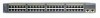
Chapter 1 Product Overview Figure 1-1 Catalyst 2900 Series XL Switches Version Number Description WS-C2912-LRE-XL 4 fixed autosensing 10/100 ports INPUT OUTPUT PWR PWR RESET TEMP FAN 9X 10X 11X 12X 12 LRE ports Cisco RPS 300 WS-C2924-LRE-XL 4 fixed autosensing 10/100 ports 24 LRE ports INPUT OUTPUT PWR PWR... 4 5 100BASE-FX 6 7 8 9 10 11 12 WS-C2924M-XL WS-C2924M-XLEM-DC 24 fixed autosensing 10/100 ports 2 expansion slots 12 MODE 1X 2X 3X Catalyst 2900 SERIES XL 4X 5X 6X 7X 8X 9X 10X 11X 100BaseFX 12X 13X 14X 15X 16X 17X 18X 19X 20X 21X 22X 23X 24X...
Chapter 1 Product Overview Figure 1-1 Catalyst 2900 Series XL Switches Version Number Description WS-C2912-LRE-XL 4 fixed autosensing 10/100 ports INPUT OUTPUT PWR PWR RESET TEMP FAN 9X 10X 11X 12X 12 LRE ports Cisco RPS 300 WS-C2924-LRE-XL 4 fixed autosensing 10/100 ports 24 LRE ports INPUT OUTPUT PWR PWR... 4 5 100BASE-FX 6 7 8 9 10 11 12 WS-C2924M-XL WS-C2924M-XLEM-DC 24 fixed autosensing 10/100 ports 2 expansion slots 12 MODE 1X 2X 3X Catalyst 2900 SERIES XL 4X 5X 6X 7X 8X 9X 10X 11X 100BaseFX 12X 13X 14X 15X 16X 17X 18X 19X 20X 21X 22X 23X 24X...

Hardware Installation Guide
Page 24
...module slots (see Figure 1-3), and up to twenty-four Long-Reach Ethernet ports (See Figure 1-4). Catalyst 2900 Series XL Hardware Installation Guide 1-4 78-6461-04 The switch supports a comprehensive set of MIB extensions and four Remote Monitoring (RMON) groups. Front-Panel Description ... display network topologies to gather link information and to display switch images to the Catalyst 2900 Series XL and Catalyst 3500 Series XL Software Configuration Guide. Front-Panel Description Depending on the switch. This section describes these interfaces: • Cluster Management Suite...
...module slots (see Figure 1-3), and up to twenty-four Long-Reach Ethernet ports (See Figure 1-4). Catalyst 2900 Series XL Hardware Installation Guide 1-4 78-6461-04 The switch supports a comprehensive set of MIB extensions and four Remote Monitoring (RMON) groups. Front-Panel Description ... display network topologies to gather link information and to display switch images to the Catalyst 2900 Series XL and Catalyst 3500 Series XL Software Configuration Guide. Front-Panel Description Depending on the switch. This section describes these interfaces: • Cluster Management Suite...

Hardware Installation Guide
Page 26
...as high-speed workstations, Cisco IP Phones, servers, hubs, routers, and other switches through , twisted-pair cable. The 10/100 ports on the Catalyst 2900 XL switches provide protocol support for more info on the Catalyst 3524-PWR XL switch, refer to the Catalyst 3500 Series XL Hardware ...Cable Specifications." When connecting the switch to an AC power source. Pinouts for 100BASE-TX traffic. These ports also can use a crossover cable. For more information about these features. Catalyst 2900 Series XL Hardware Installation Guide 1-6 78-6461-04 Cisco IP Phones-connected to the...
...as high-speed workstations, Cisco IP Phones, servers, hubs, routers, and other switches through , twisted-pair cable. The 10/100 ports on the Catalyst 2900 XL switches provide protocol support for more info on the Catalyst 3524-PWR XL switch, refer to the Catalyst 3500 Series XL Hardware ...Cable Specifications." When connecting the switch to an AC power source. Pinouts for 100BASE-TX traffic. These ports also can use a crossover cable. For more information about these features. Catalyst 2900 Series XL Hardware Installation Guide 1-6 78-6461-04 Cisco IP Phones-connected to the...

Hardware Installation Guide
Page 27
... the same Catalyst 2900 LRE XL switch, and you can hot swap the CPE devices without powering down the switch or disrupting the other telephone services are configured for each CPE device can be connected to the patch panel through a private branch exchange (PBX) switch, a Cisco LRE 48...data (high-frequency) and voice (low-frequency) traffic from the telephone line to the Catalyst 2900 Series XL and Catalyst 3500 Series XL Software Configuration Guide. For information about the Cisco LRE CPE devices, refer to private telephone networks and the public system telephone network 78-6461...
... the same Catalyst 2900 LRE XL switch, and you can hot swap the CPE devices without powering down the switch or disrupting the other telephone services are configured for each CPE device can be connected to the patch panel through a private branch exchange (PBX) switch, a Cisco LRE 48...data (high-frequency) and voice (low-frequency) traffic from the telephone line to the Catalyst 2900 Series XL and Catalyst 3500 Series XL Software Configuration Guide. For information about the Cisco LRE CPE devices, refer to private telephone networks and the public system telephone network 78-6461...

Hardware Installation Guide
Page 28
...-Reach Ethernet (LRE) products are for the Cisco LRE 48 POTS Splitter. For more information about homologated POTS splitters, contact your Cisco sales representative. Each module port is internally switched to other switch ports and is required to directly connect to the Installation Notes for the Catalyst 2900 XL hot-swappable modules. Table 1-1 lists the...
...-Reach Ethernet (LRE) products are for the Cisco LRE 48 POTS Splitter. For more information about homologated POTS splitters, contact your Cisco sales representative. Each module port is internally switched to other switch ports and is required to directly connect to the Installation Notes for the Catalyst 2900 XL hot-swappable modules. Table 1-1 lists the...

Hardware Installation Guide
Page 29
... in module slots and tighten the thumb screws. A power-on expansion modules for the Catalyst 2900 Series XL and Catalyst 3500 Series XL Switches. If you insert them in a 2924M XL or Catalyst 2912MF XL switch (both supporting 8192 MAC addresses), the module fails POST. You can use to select... configure themselves when you install one of the LEDs and the Mode button that you use the switch LEDs to the Catalyst 2900 Series XL Modules Installation Guide and the Catalyst 2900 Series XL ATM Modules Installation and Configuration Guide for detailed information on self-test (POST) ...
... in module slots and tighten the thumb screws. A power-on expansion modules for the Catalyst 2900 Series XL and Catalyst 3500 Series XL Switches. If you insert them in a 2924M XL or Catalyst 2912MF XL switch (both supporting 8192 MAC addresses), the module fails POST. You can use to select... configure themselves when you install one of the LEDs and the Mode button that you use the switch LEDs to the Catalyst 2900 Series XL Modules Installation Guide and the Catalyst 2900 Series XL ATM Modules Installation and Configuration Guide for detailed information on self-test (POST) ...

Hardware Installation Guide
Page 30
...section except the utilization meter (UTL) are visible on the Cluster Management Suite (CMS) window and, if the switch is a cluster member, on the CMS Cluster Manager window. Figure 1-5 Catalyst 2912 XL, 2924 XL, and 2924C XL LEDs 10/100 port LEDs System LED Port mode LEDs MODE 1X ...6X 7X Mode RPS button LED 47288 1-10 Catalyst 2900 Series XL Hardware Installation Guide 78-6461-04 The Catalyst 2900 Series XL and Catalyst 3500 Series XL Software Configuration Guide describes how to use CMS to manage standalone or individual switches and how to use cluster management software to manage...
...section except the utilization meter (UTL) are visible on the Cluster Management Suite (CMS) window and, if the switch is a cluster member, on the CMS Cluster Manager window. Figure 1-5 Catalyst 2912 XL, 2924 XL, and 2924C XL LEDs 10/100 port LEDs System LED Port mode LEDs MODE 1X ...6X 7X Mode RPS button LED 47288 1-10 Catalyst 2900 Series XL Hardware Installation Guide 78-6461-04 The Catalyst 2900 Series XL and Catalyst 3500 Series XL Software Configuration Guide describes how to use CMS to manage standalone or individual switches and how to use cluster management software to manage...

Hardware Installation Guide
Page 32
... the System LED colors during POST, see the "Powering On the Switch and Running POST" section on page 2-24. 1-12 Catalyst 2900 Series XL Hardware Installation Guide 78-6461-04 System is receiving power and functioning properly. Front-Panel Description Figure 1-7 Catalyst 2912 LRE XL and 2924 LRE XL LEDs 10/100 port...
... the System LED colors during POST, see the "Powering On the Switch and Running POST" section on page 2-24. 1-12 Catalyst 2900 Series XL Hardware Installation Guide 78-6461-04 System is receiving power and functioning properly. Front-Panel Description Figure 1-7 Catalyst 2912 LRE XL and 2924 LRE XL LEDs 10/100 port...

Hardware Installation Guide
Page 33
... is not a recommended configuration. Chapter 1 Product Overview Front-Panel Description RPS LED The Catalyst 2912 LRE XL and Catalyst 2924 LRE XL switches use the Cisco RPS 600 (model PWR600-AC-RPS). All other Catalyst 2900 XL and Catalyst 3500 XL switches use the Cisco RPS 300 (model PWR300-AC-RPS-N1). RPS is providing power to another...
... is not a recommended configuration. Chapter 1 Product Overview Front-Panel Description RPS LED The Catalyst 2912 LRE XL and Catalyst 2924 LRE XL switches use the Cisco RPS 600 (model PWR600-AC-RPS). All other Catalyst 2900 XL and Catalyst 3500 XL switches use the Cisco RPS 300 (model PWR300-AC-RPS-N1). RPS is providing power to another...

Hardware Installation Guide
Page 34
... Contact Cisco Systems. The internal power supply in use by the switch. (See Figure 1-8.) The port duplex mode: full duplex or half duplex, and default modes: • 10/100 ports: auto • 100BaseFX ports: auto • Gigabit ports: auto The port operating speed: 10 or 100 Mbps. 1-14 Catalyst 2900 ... allocated to this device). Press the Standby/Active button on the Catalyst 2912 XL, 2924C XL, 2924 XL, 2924MF XL, 2924M XL, and 2924M XL DC Switches Mode LED STAT UTL FDUP 100 Port Mode Port status Switch utilization Port duplex mode Port speed Description The port status. Front-...
... Contact Cisco Systems. The internal power supply in use by the switch. (See Figure 1-8.) The port duplex mode: full duplex or half duplex, and default modes: • 10/100 ports: auto • 100BaseFX ports: auto • Gigabit ports: auto The port operating speed: 10 or 100 Mbps. 1-14 Catalyst 2900 ... allocated to this device). Press the Standby/Active button on the Catalyst 2912 XL, 2924C XL, 2924 XL, 2924MF XL, 2924M XL, and 2924M XL DC Switches Mode LED STAT UTL FDUP 100 Port Mode Port status Switch utilization Port duplex mode Port speed Description The port status. Front-...

Hardware Installation Guide
Page 35
... default setting is active, the 10/100 switch ports on the Catalyst 2912 LRE XL and Catalyst 2924 LRE XL switches. The port operating speed: 10 or 100 Mbps. Default mode on all Catalyst 2900 XL and Catalyst 3500 XL switches except the Catalyst 2912 LRE XL and Catalyst 2924 LRE XL switches. The port duplex mode: full duplex or...
... default setting is active, the 10/100 switch ports on the Catalyst 2912 LRE XL and Catalyst 2924 LRE XL switches. The port operating speed: 10 or 100 Mbps. Default mode on all Catalyst 2900 XL and Catalyst 3500 XL switches except the Catalyst 2912 LRE XL and Catalyst 2924 LRE XL switches. The port duplex mode: full duplex or...


