
Hardware Installation Guide
Page 8
... B-5 Identifying a Rollover Cable B-6 Connecting to a PC B-6 Connecting to a Terminal B-7 Translated Safety Warnings C-1 Attaching the Cisco RPS (model PWR600-AC-RPS) C-1 Attaching the Cisco RPS (model PWR300-AC-RPS-N1) C-2 Qualified Personnel Warning C-3 Installation Warning C-4 Jewelry Removal Warning C-5 Stacking the Chassis... Breaker (15A) Warning C-12 Grounded Equipment Warning C-14 Supply Circuit Warning C-15 Voltage Warning C-16 Power Supply Warning C-17 Lightning Activity Warning C-19 Product Disposal Warning C-21 Catalyst 2900 Series XL Hardware Installation Guide viii 78-6461-04
... B-5 Identifying a Rollover Cable B-6 Connecting to a PC B-6 Connecting to a Terminal B-7 Translated Safety Warnings C-1 Attaching the Cisco RPS (model PWR600-AC-RPS) C-1 Attaching the Cisco RPS (model PWR300-AC-RPS-N1) C-2 Qualified Personnel Warning C-3 Installation Warning C-4 Jewelry Removal Warning C-5 Stacking the Chassis... Breaker (15A) Warning C-12 Grounded Equipment Warning C-14 Supply Circuit Warning C-15 Voltage Warning C-16 Power Supply Warning C-17 Lightning Activity Warning C-19 Product Disposal Warning C-21 Catalyst 2900 Series XL Hardware Installation Guide viii 78-6461-04
Hardware Installation Guide
Page 41
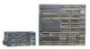
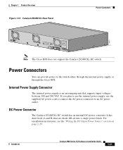
...the supplied AC power cord to connect the AC power connector to the switch either through the internal power supply or through the Cisco RPS. DC Power Connector The Catalyst 2924M XL DC switch has an internal DC-power converter. For installation instructions, see the ...are diode-OR-ed into a single power block. It has dual feeds (A and B) that supports input voltages between 100 and 240 VAC. B +- Chapter 1 Product Overview Figure 1-13 Catalyst 2924M XL Rear Panel Power Connectors 74070 CONSOLE BERFEOFREERPOCTOWONEMNRAENCUTAINL G DC INPUT ICNUPRURTE: 3N6T:- 72 4-2A A ...
...the supplied AC power cord to connect the AC power connector to the switch either through the internal power supply or through the Cisco RPS. DC Power Connector The Catalyst 2924M XL DC switch has an internal DC-power converter. For installation instructions, see the ...are diode-OR-ed into a single power block. It has dual feeds (A and B) that supports input voltages between 100 and 240 VAC. B +- Chapter 1 Product Overview Figure 1-13 Catalyst 2924M XL Rear Panel Power Connectors 74070 CONSOLE BERFEOFREERPOCTOWONEMNRAENCUTAINL G DC INPUT ICNUPRURTE: 3N6T:- 72 4-2A A ...

Hardware Installation Guide
Page 42
...two AC input power modules for four external devices that has an input supply voltage from -36 to -72 VDC. RPS Connector on the Catalyst 2912 XL, 2924C XL, 2924 XL, 2924MF XL, and 2924M XL Switches The Cisco RPS 600 (model PWR600-AC-RPS) provides a quasi-redundant power source for...power source that use up to 150W DC each. Cisco RPS Connector Specific Cisco RPS models support specific Catalyst 2900 XL switches: • Cisco RPS 600 (model PWR600-AC-RPS)-supports the Catalyst 2912 XL, 2924C XL, 2924 XL, 2924MF XL, and 2924M XL switches. • Cisco RPS 300 (model PWR300-AC-RPS-N1)-supports ...
...two AC input power modules for four external devices that has an input supply voltage from -36 to -72 VDC. RPS Connector on the Catalyst 2912 XL, 2924C XL, 2924 XL, 2924MF XL, and 2924M XL Switches The Cisco RPS 600 (model PWR600-AC-RPS) provides a quasi-redundant power source for...power source that use up to 150W DC each. Cisco RPS Connector Specific Cisco RPS models support specific Catalyst 2900 XL switches: • Cisco RPS 600 (model PWR600-AC-RPS)-supports the Catalyst 2912 XL, 2924C XL, 2924 XL, 2924MF XL, and 2924M XL switches. • Cisco RPS 300 (model PWR300-AC-RPS-N1)-supports ...
Hardware Installation Guide
Page 47
Warning Do not touch the power supply when the power cord is connected. If the voltage indicated on the phase conductors (all national laws and regulations. 78-6461-04 Catalyst 2900 Series XL Hardware Installation Guide 2-3 Ensure that a fuse or circuit breaker no larger than 120 VAC,... system or connect or disconnect cables during normal use. Warning Ultimate disposal of lightning activity. For systems without a power switch, line voltages are present within the power supply when the power cord is connected to earth ground during periods of this product should ...
Warning Do not touch the power supply when the power cord is connected. If the voltage indicated on the phase conductors (all national laws and regulations. 78-6461-04 Catalyst 2900 Series XL Hardware Installation Guide 2-3 Ensure that a fuse or circuit breaker no larger than 120 VAC,... system or connect or disconnect cables during normal use. Warning Ultimate disposal of lightning activity. For systems without a power switch, line voltages are present within the power supply when the power cord is connected to earth ground during periods of this product should ...
Hardware Installation Guide
Page 100
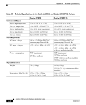
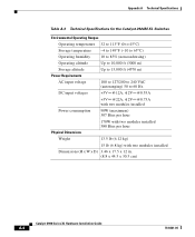
Appendix A Technical Specifications Table A-1 Technical Specifications for the Catalyst 2912 XL and Catalyst 2912MF XL Switches Environmental Ranges Operating temperature Storage temperature Operating humidity Operating altitude Storage altitude Power Requirements AC input voltage DC input voltages Catalyst 2912 XL 32 to 113°F (0 to 45°C) -4 ...(maximum) 239 Btus per hour 7 lb (3.2 kg) Dimensions (H x W x D) 1.73 x 17.5 x 9.79 in. (4.4 x 44.5 x 24.8 cm) Catalyst 2912MF XL 32 to 113°F (0 to 45°C) -4 to 149°F (-10 to 65°C) 10 to 85% (noncondensing) Up to 10,000 ft...
Appendix A Technical Specifications Table A-1 Technical Specifications for the Catalyst 2912 XL and Catalyst 2912MF XL Switches Environmental Ranges Operating temperature Storage temperature Operating humidity Operating altitude Storage altitude Power Requirements AC input voltage DC input voltages Catalyst 2912 XL 32 to 113°F (0 to 45°C) -4 ...(maximum) 239 Btus per hour 7 lb (3.2 kg) Dimensions (H x W x D) 1.73 x 17.5 x 9.79 in. (4.4 x 44.5 x 24.8 cm) Catalyst 2912MF XL 32 to 113°F (0 to 45°C) -4 to 149°F (-10 to 65°C) 10 to 85% (noncondensing) Up to 10,000 ft...

Hardware Installation Guide
Page 101
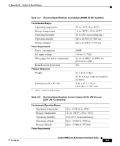
...Switches Catalyst 2924 XL Environmental Operating Ranges Operating temperature 32 to 113°F (0 to 45°C) Storage temperature -4 to 149°F (-10 to 65°C) Operating humidity 10 to 85% (noncondensing) Operating altitude Up to 10,000 ft (3000 m) Storage altitude Power Requirements Up to 15,000 ft (4570 m) AC input voltage... DC input voltages 100 to 127/200 to 240 VAC (autoranging) 50 to -14 dBm 78-6461-04 Catalyst 2900 Series XL Hardware Installation Guide A-3 Transmit - 1. nm = ...
...Switches Catalyst 2924 XL Environmental Operating Ranges Operating temperature 32 to 113°F (0 to 45°C) Storage temperature -4 to 149°F (-10 to 65°C) Operating humidity 10 to 85% (noncondensing) Operating altitude Up to 10,000 ft (3000 m) Storage altitude Power Requirements Up to 15,000 ft (4570 m) AC input voltage... DC input voltages 100 to 127/200 to 240 VAC (autoranging) 50 to -14 dBm 78-6461-04 Catalyst 2900 Series XL Hardware Installation Guide A-3 Transmit - 1. nm = ...
Hardware Installation Guide
Page 102
...Catalyst 2924M XL Switches Environmental Operating Ranges Operating temperature 32 to 113°F (0 to 45°C) Storage temperature -4 to 149°F (-10 to 65°C) Operating humidity 10 to 85% (noncondensing) Operating altitude Up to 10,000 ft (3000 m) Storage altitude Up to 15,000 ft (4570 m) Power Requirements AC input voltage... 100 to 127/200 to 240 VAC (autoranging) 50 to 60 Hz DC input voltages +5V @12A, +12V @0.55A +5V @22A, +12V @0.75A with two modules installed Power ...
...Catalyst 2924M XL Switches Environmental Operating Ranges Operating temperature 32 to 113°F (0 to 45°C) Storage temperature -4 to 149°F (-10 to 65°C) Operating humidity 10 to 85% (noncondensing) Operating altitude Up to 10,000 ft (3000 m) Storage altitude Up to 15,000 ft (4570 m) Power Requirements AC input voltage... 100 to 127/200 to 240 VAC (autoranging) 50 to 60 Hz DC input voltages +5V @12A, +12V @0.55A +5V @22A, +12V @0.75A with two modules installed Power ...
Hardware Installation Guide
Page 103
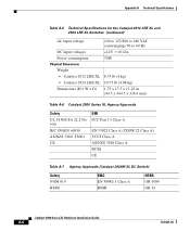
... Ranges Operating temperature Storage temperature Operating humidity Operating altitude Storage altitude Power Requirements Power consumption DC input voltage Wire gauge for the Catalyst 2912 LRE XL and 2924 LRE XL Switches Environmental Operating Ranges Operating temperature Storage temperature Operating humidity Operating altitude Storage altitude Power Requirements 32 to 113°F (0 to 45°...
... Ranges Operating temperature Storage temperature Operating humidity Operating altitude Storage altitude Power Requirements Power consumption DC input voltage Wire gauge for the Catalyst 2912 LRE XL and 2924 LRE XL Switches Environmental Operating Ranges Operating temperature Storage temperature Operating humidity Operating altitude Storage altitude Power Requirements 32 to 113°F (0 to 45°...
Hardware Installation Guide
Page 104
... Table A-5 Technical Specifications for the Catalyst 2912 LRE XL and 2924 LRE XL Switches (continued) AC input voltage 100 to 127/200 to 240 VAC (autoranging) 50 to 60 Hz DC input voltages +12V @12A Power consumption 70W Physical Dimensions Weight • Catalyst 2912 LRE XL 8.75 lb (4 kg) • Catalyst 2924 LRE XL 10.75... 3260, TS001 CE EMI FCC Part 15 Class A EN 55022 Class A (CISPR 22 Class A) VCCI Class A AS/NZS 3548 Class A BCIQ CE Table A-7 Agency Approvals (Catalyst 2924M XL DC Switch) Safety NOM 019 BSMI EMC EN 50082-1 Class A BSMI NEBS GR-1089 GR-63...
... Table A-5 Technical Specifications for the Catalyst 2912 LRE XL and 2924 LRE XL Switches (continued) AC input voltage 100 to 127/200 to 240 VAC (autoranging) 50 to 60 Hz DC input voltages +12V @12A Power consumption 70W Physical Dimensions Weight • Catalyst 2912 LRE XL 8.75 lb (4 kg) • Catalyst 2924 LRE XL 10.75... 3260, TS001 CE EMI FCC Part 15 Class A EN 55022 Class A (CISPR 22 Class A) VCCI Class A AS/NZS 3548 Class A BCIQ CE Table A-7 Agency Approvals (Catalyst 2924M XL DC Switch) Safety NOM 019 BSMI EMC EN 50082-1 Class A BSMI NEBS GR-1089 GR-63...

Hardware Installation Guide
Page 161
Index RJ-45-to-DB-25 B-7 RJ-45-to-DB-9 B-6 terminal emulation software 2-42 TN power warning C-10 translated warnings C-1 to C-28 U UTL LED 1-14, 1-16 V VDSL defined 1-1 very-high-data-rate digital subscriber line See VDSL voltage warning C-16 W warnings defined xiii to xv translated C-1 to C-28 78-6461-04 Catalyst 2900 Series XL Hardware Installation Guide IN-7
Index RJ-45-to-DB-25 B-7 RJ-45-to-DB-9 B-6 terminal emulation software 2-42 TN power warning C-10 translated warnings C-1 to C-28 U UTL LED 1-14, 1-16 V VDSL defined 1-1 very-high-data-rate digital subscriber line See VDSL voltage warning C-16 W warnings defined xiii to xv translated C-1 to C-28 78-6461-04 Catalyst 2900 Series XL Hardware Installation Guide IN-7