
Hardware Installation Guide
Page 11
... install a switch, and provides troubleshooting information and specifications. We assume that might arise when you are familiar with the concepts and terminology of the problems that you are installing the switch. 78-6461-04 Catalyst 2900 Series XL Hardware Installation Guide xi Purpose The Catalyst 2900 Series XL Hardware Installation Guide documents the hardware features of the switches, explains how to identify and resolve some of Ethernet and local area networking. Chapter 2, "Installation...
... install a switch, and provides troubleshooting information and specifications. We assume that might arise when you are familiar with the concepts and terminology of the problems that you are installing the switch. 78-6461-04 Catalyst 2900 Series XL Hardware Installation Guide xi Purpose The Catalyst 2900 Series XL Hardware Installation Guide documents the hardware features of the switches, explains how to identify and resolve some of Ethernet and local area networking. Chapter 2, "Installation...

Hardware Installation Guide
Page 21
...; Autonegotiates speed and duplex operation on all 10/100 ports • Operates in full-duplex mode on all 100BASE-FX ports • Checks for errors on a received packet, determines the destination port, stores the packet in shared memory, and then forwards the packet to the destination port 78-6461-04 Catalyst 2900 Series XL Hardware Installation Guide 1-1 The switches can connect workstations, Cisco IP Phones, and other network devices such as backbone switches, aggregating 10...
...; Autonegotiates speed and duplex operation on all 10/100 ports • Operates in full-duplex mode on all 100BASE-FX ports • Checks for errors on a received packet, determines the destination port, stores the packet in shared memory, and then forwards the packet to the destination port 78-6461-04 Catalyst 2900 Series XL Hardware Installation Guide 1-1 The switches can connect workstations, Cisco IP Phones, and other network devices such as backbone switches, aggregating 10...

Hardware Installation Guide
Page 22
...-T, Gigabit Ethernet, and asynchronous transfer mode (ATM) modules • On the Catalyst 2924M XL DC switch, a direct current (DC) power converter • On the Catalyst 2912 LRE XL and 2924 LRE XL switches, up to 24 LRE ports through one RJ-21 connector and hot swapping capability with the Cisco LRE customer premises equipment (CPE) devices • Supports up to 2048 MAC addresses on...
...-T, Gigabit Ethernet, and asynchronous transfer mode (ATM) modules • On the Catalyst 2924M XL DC switch, a direct current (DC) power converter • On the Catalyst 2912 LRE XL and 2924 LRE XL switches, up to 24 LRE ports through one RJ-21 connector and hot swapping capability with the Cisco LRE customer premises equipment (CPE) devices • Supports up to 2048 MAC addresses on...

Hardware Installation Guide
Page 24
... from a remote management station. • Simple network management protocol (SNMP)-SNMP provides a means to the switch console port or by using Telnet from anywhere in your network through a web browser such as CiscoWorks2000 LAN Management Suite (LMS) and HP OpenView. You can have a set of LEDs and a Mode button. You can manage the switch from the CLI. and port-level settings. • Command-line Interface (CLI)-The switch IOS CLI software is already installed on the model, the switch front panels can manage switch configuration settings, performance...
... from a remote management station. • Simple network management protocol (SNMP)-SNMP provides a means to the switch console port or by using Telnet from anywhere in your network through a web browser such as CiscoWorks2000 LAN Management Suite (LMS) and HP OpenView. You can have a set of LEDs and a Mode button. You can manage the switch from the CLI. and port-level settings. • Command-line Interface (CLI)-The switch IOS CLI software is already installed on the model, the switch front panels can manage switch configuration settings, performance...

Hardware Installation Guide
Page 26
.... The 10/100 ports on the Catalyst 3524-PWR XL switch, refer to the Catalyst 3500 Series XL Hardware Installation Guide. Catalyst 2900 Series XL Hardware Installation Guide 1-6 78-6461-04 When connecting the switch to switches or hubs, use Category 3 and 4 cables. Refer to the Catalyst 2900 Series XL and Catalyst 3500 Series XL Software Configuration Guide for more info on the Catalyst 2900 XL switches provide protocol support for autonegotiation, the port senses the speed and duplex settings of half duplex, full duplex, 10 Mbps...
.... The 10/100 ports on the Catalyst 3524-PWR XL switch, refer to the Catalyst 3500 Series XL Hardware Installation Guide. Catalyst 2900 Series XL Hardware Installation Guide 1-6 78-6461-04 When connecting the switch to switches or hubs, use Category 3 and 4 cables. Refer to the Catalyst 2900 Series XL and Catalyst 3500 Series XL Software Configuration Guide for more info on the Catalyst 2900 XL switches provide protocol support for autonegotiation, the port senses the speed and duplex settings of half duplex, full duplex, 10 Mbps...

Hardware Installation Guide
Page 27
... PBX routes voice traffic to the switch and private branch exchange (PBX) switch or Public-Switched Telephone Network (PSTN). or 62.5/125-micron multimode fiber-optic cabling. Long-Reach Ethernet Ports The Long-Reach Ethernet (LRE) ports (Figure 1-4) use 50/125- The default mode for full-duplex operation, the connection can hot swap the CPE devices without powering down the switch or disrupting the other telephone services are configured for each...
... PBX routes voice traffic to the switch and private branch exchange (PBX) switch or Public-Switched Telephone Network (PSTN). or 62.5/125-micron multimode fiber-optic cabling. Long-Reach Ethernet Ports The Long-Reach Ethernet (LRE) ports (Figure 1-4) use 50/125- The default mode for full-duplex operation, the connection can hot swap the CPE devices without powering down the switch or disrupting the other telephone services are configured for each...

Hardware Installation Guide
Page 28
... digital PBX switch services use frequencies above 700 kHz. [CSCdu73260] If the installation does not have a PBX, a homologated POTS splitter is required to directly connect to 700 kHz frequency range. Table 1-1 Expansion Modules Module Type 10/100 Ethernet 100 BASE-FX Model Number WS-X2914-XL WS-X2914-XL-V WS-X2922-XL WS-X2922-XL-V WS-X2924-XL-V Catalyst 2900 Series XL Hardware Installation Guide 1-8 78-6461...
... digital PBX switch services use frequencies above 700 kHz. [CSCdu73260] If the installation does not have a PBX, a homologated POTS splitter is required to directly connect to 700 kHz frequency range. Table 1-1 Expansion Modules Module Type 10/100 Ethernet 100 BASE-FX Model Number WS-X2914-XL WS-X2914-XL-V WS-X2922-XL WS-X2922-XL-V WS-X2924-XL-V Catalyst 2900 Series XL Hardware Installation Guide 1-8 78-6461...

Hardware Installation Guide
Page 29
... Overview Front-Panel Description Table 1-1 Expansion Modules (continued) Module Type Model Number 1000BASE-T 1Ethernet Gigabit WS-X2932-XL WS-X2931-XL ATM WS-X2971-XL WS-X2972-XL WS-X2951-XL WS-X2961-XL 1. If you install one of the LEDs and the Mode button that you insert them in a 2924M XL or Catalyst 2912MF XL switch (both supporting 8192 MAC addresses), the module fails POST. Catalyst 2900 Series XL Hardware Installation Guide 1-9
... Overview Front-Panel Description Table 1-1 Expansion Modules (continued) Module Type Model Number 1000BASE-T 1Ethernet Gigabit WS-X2932-XL WS-X2931-XL ATM WS-X2971-XL WS-X2972-XL WS-X2951-XL WS-X2961-XL 1. If you install one of the LEDs and the Mode button that you insert them in a 2924M XL or Catalyst 2912MF XL switch (both supporting 8192 MAC addresses), the module fails POST. Catalyst 2900 Series XL Hardware Installation Guide 1-9

Hardware Installation Guide
Page 34
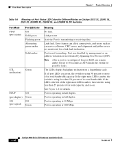
... this device). Table 1-6 and Table 1-7 list the port LED colors. These port LEDs, as a group or individually, display information about the switch and about the individual ports. Contact Cisco Systems. The internal power supply in use by the switch. (See Figure 1-8.) The port duplex mode: full duplex or half duplex, and default modes: • 10/100 ports: auto • 100BaseFX ports: auto • Gigabit ports: auto The port operating speed: 10 or 100 Mbps. 1-14 Catalyst 2900 Series XL Hardware Installation Guide 78-6461-04...
... this device). Table 1-6 and Table 1-7 list the port LED colors. These port LEDs, as a group or individually, display information about the switch and about the individual ports. Contact Cisco Systems. The internal power supply in use by the switch. (See Figure 1-8.) The port duplex mode: full duplex or half duplex, and default modes: • 10/100 ports: auto • 100BaseFX ports: auto • Gigabit ports: auto The port operating speed: 10 or 100 Mbps. 1-14 Catalyst 2900 Series XL Hardware Installation Guide 78-6461-04...
Hardware Installation Guide
Page 36
... port LED can affect connectivity, and errors such as STP checks the switch for details. Link fault. Port is operating at 100 Mbps. 1-16 Catalyst 2900 Series XL Hardware Installation Guide 78-6461-04 The LEDs display backplane utilization on Catalyst 2912 XL, 2924C XL, 2924 XL, 2924MF XL, 2924M XL, and 2924M XL DC Switches Port Mode STAT (port status) Port LED Color Off Solid green Flashing green Alternating green-amber Solid amber UTL Green (utilization) FDUP (port duplex) 100 (port speed) Off Green...
... port LED can affect connectivity, and errors such as STP checks the switch for details. Link fault. Port is operating at 100 Mbps. 1-16 Catalyst 2900 Series XL Hardware Installation Guide 78-6461-04 The LEDs display backplane utilization on Catalyst 2912 XL, 2924C XL, 2924 XL, 2924MF XL, 2924M XL, and 2924M XL DC Switches Port Mode STAT (port status) Port LED Color Off Solid green Flashing green Alternating green-amber Solid amber UTL Green (utilization) FDUP (port duplex) 100 (port speed) Off Green...
Hardware Installation Guide
Page 37
...-duplex mode. 78-6461-04 Catalyst 2900 Series XL Hardware Installation Guide 1-17 Green LRE link present on the LRE port. Amber LRE port on the switch and WALL port on the LRE CPE unable to a LRE CPE. DUPLX Blinking amber Cisco IOS Release 12.0(5.x)WC1/ WC21 Activity on the 10/100 ports. Cyan (off ) LRE port or remote CPE Ethernet port is reconfigured, the port LED can remain amber for up to reflect Ethernet link status. The Ethernet link default settings...
...-duplex mode. 78-6461-04 Catalyst 2900 Series XL Hardware Installation Guide 1-17 Green LRE link present on the LRE port. Amber LRE port on the switch and WALL port on the LRE CPE unable to a LRE CPE. DUPLX Blinking amber Cisco IOS Release 12.0(5.x)WC1/ WC21 Activity on the 10/100 ports. Cyan (off ) LRE port or remote CPE Ethernet port is reconfigured, the port LED can remain amber for up to reflect Ethernet link status. The Ethernet link default settings...

Hardware Installation Guide
Page 38
... not provide information about the connected Cisco 575 LRE CPE devices. The Catalyst 2900 LRE XL switches do not support the Cisco 585 LRE CPE devices. 2. Figure 1-9 shows bandwidth utilization percentages displayed by the right-most LEDs. The LEDs on Catalyst 2900 LRE XL switches with this release or higher, use the Port Settings window or the show remote interfaces status user EXEC command. Figure 1-9 Bandwidth Utilization 47293 SYSTEM...
... not provide information about the connected Cisco 575 LRE CPE devices. The Catalyst 2900 LRE XL switches do not support the Cisco 585 LRE CPE devices. 2. Figure 1-9 shows bandwidth utilization percentages displayed by the right-most LEDs. The LEDs on Catalyst 2900 LRE XL switches with this release or higher, use the Port Settings window or the show remote interfaces status user EXEC command. Figure 1-9 Bandwidth Utilization 47293 SYSTEM...

Hardware Installation Guide
Page 69
... 2 Unpack the shipping box, and verify its contents. Chapter 2 Installation Connecting to DC Power The System LED flashes green, and the RPS LED turns off . In addition to the items described in turn off . If POST fails, refer to Chapter 3, "Troubleshooting," to a DC-input power source. As each turn off in the Catalyst 2900 Series XL Installation Guide, the switch is operational. Obtain the following necessary tools and equipment...
... 2 Unpack the shipping box, and verify its contents. Chapter 2 Installation Connecting to DC Power The System LED flashes green, and the RPS LED turns off . In addition to the items described in turn off . If POST fails, refer to Chapter 3, "Troubleshooting," to a DC-input power source. As each turn off in the Catalyst 2900 Series XL Installation Guide, the switch is operational. Obtain the following necessary tools and equipment...

Hardware Installation Guide
Page 79
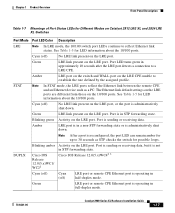
... Switch Connecting to switches or repeaters, use a crossover Category 5 cable. To maximize performance, choose one of these steps to connect to 10BASE-T and 100BASE-TX devices: Step 1 When connecting to workstations, servers, routers, and Cisco IP Phones, connect a straight-through Category 5 cable to operate at the speed of the connection. Pinouts for configuring the 10/100 Ethernet ports: • Let the ports autonegotiate both speed and duplex. • Set the port speed and duplex...
... Switch Connecting to switches or repeaters, use a crossover Category 5 cable. To maximize performance, choose one of these steps to connect to 10BASE-T and 100BASE-TX devices: Step 1 When connecting to workstations, servers, routers, and Cisco IP Phones, connect a straight-through Category 5 cable to operate at the speed of the connection. Pinouts for configuring the 10/100 Ethernet ports: • Let the ports autonegotiate both speed and duplex. • Set the port speed and duplex...
Hardware Installation Guide
Page 82
... other switch ports. 2-38 Catalyst 2900 Series XL Hardware Installation Guide 78-6461-04 This takes about 30 seconds, and then the port LED turns green. Repeat Steps 1 through a patch panel. The port LED is amber while the STP discovers the topology and searches for solutions to connect each 100BASE-FX port. Note You can connect both the switch and the connected device have established link. The port LED turns on the switch model, you can connect...
... other switch ports. 2-38 Catalyst 2900 Series XL Hardware Installation Guide 78-6461-04 This takes about 30 seconds, and then the port LED turns green. Repeat Steps 1 through a patch panel. The port LED is amber while the STP discovers the topology and searches for solutions to connect each 100BASE-FX port. Note You can connect both the switch and the connected device have established link. The port LED turns on the switch model, you can connect...
Hardware Installation Guide
Page 85
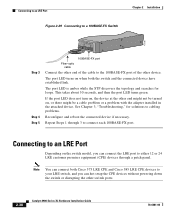
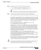
...-LRE-48), refer to the Catalyst 2900 Series XL and Catalyst 3500 Series XL Software Configuration Guide. For more information about the Cisco LRE CPE devices, refer to the PSTN. Note If a connection to a telephone network is not required at all, a splitter is required to directly connect to the Cisco LRE CPE Hardware Installation Guide. The splitter routes LRE data (high-frequency) and voice (low-frequency) traffic from the telephone line to...
...-LRE-48), refer to the Catalyst 2900 Series XL and Catalyst 3500 Series XL Software Configuration Guide. For more information about the Cisco LRE CPE devices, refer to the PSTN. Note If a connection to a telephone network is not required at all, a splitter is required to directly connect to the Cisco LRE CPE Hardware Installation Guide. The splitter routes LRE data (high-frequency) and voice (low-frequency) traffic from the telephone line to...

Hardware Installation Guide
Page 86
... the "Cable and Adapter Specifications" section on page B-4. You can change the port baud rate to a terminal. or terminal-emulation software to the Catalyst 2900 Series XL Modules Installation Guide and the Catalyst 2900 Series XL ATM Modules Installation and Configuration Guide. Connecting to the Console Port Use the supplied rollover cable and DB-9 adapter to connect a PC to the switch: Step 1 Step 2 Configure your PC or terminal possible during the setup program. Follow these switch console port default characteristics: • 9600 baud • 8 data bits •...
... the "Cable and Adapter Specifications" section on page B-4. You can change the port baud rate to a terminal. or terminal-emulation software to the Catalyst 2900 Series XL Modules Installation Guide and the Catalyst 2900 Series XL ATM Modules Installation and Configuration Guide. Connecting to the Console Port Use the supplied rollover cable and DB-9 adapter to connect a PC to the switch: Step 1 Step 2 Configure your PC or terminal possible during the setup program. Follow these switch console port default characteristics: • 9600 baud • 8 data bits •...
Hardware Installation Guide
Page 89
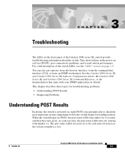
... switch. CH A P T E R 3 Troubleshooting The LEDs on , eight POSTs run automatically to 8x each turn off in the power-on page 1-9. See the Catalyst 2900 Series XL and Catalyst 3500 Series XL Software Configuration Guide, the Catalyst 2900 Series XL and Catalyst 3500 Series XL Command Reference, or the documentation that came with number 1x. The port status LEDs for details. You can also get statistics from the browser interface, from the command-line interface (CLI), or from an SNMP...
... switch. CH A P T E R 3 Troubleshooting The LEDs on , eight POSTs run automatically to 8x each turn off in the power-on page 1-9. See the Catalyst 2900 Series XL and Catalyst 3500 Series XL Software Configuration Guide, the Catalyst 2900 Series XL and Catalyst 3500 Series XL Command Reference, or the documentation that came with number 1x. The port status LEDs for details. You can also get statistics from the browser interface, from the command-line interface (CLI), or from an SNMP...
Hardware Installation Guide
Page 95
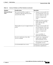
...; Change to establish an LRE link with the profile selected by terminating them with other services in bundle. • Consider use of spectrally incompatible services. Excessive interference from other services. • Restrict the use of improving trunk quality. Chapter 3 Troubleshooting Diagnosing Problems Table 3-2 Common Problems and Their Solutions (continued) Symptom LRE status LED stays amber. Consult Cisco sales representative for installation optimization. 78-6461-04 Catalyst 2900 Series XL Hardware Installation Guide 3-7 For...
...; Change to establish an LRE link with the profile selected by terminating them with other services in bundle. • Consider use of spectrally incompatible services. Excessive interference from other services. • Restrict the use of improving trunk quality. Chapter 3 Troubleshooting Diagnosing Problems Table 3-2 Common Problems and Their Solutions (continued) Symptom LRE status LED stays amber. Consult Cisco sales representative for installation optimization. 78-6461-04 Catalyst 2900 Series XL Hardware Installation Guide 3-7 For...

Hardware Installation Guide
Page 111
... order a kit (part number ACS-DSBUASYN=) containing this adapter from Cisco. 78-6461-04 Catalyst 2900 Series XL Hardware Installation Guide B-7 Appendix B Connectors and Cable Specifications Identifying a Rollover Cable Table B-2 Console Port Signaling and Cabling Using a DB-9 Adapter Console Port (DTE) RJ-45-to-RJ-45 Rollover Cable Signal RJ-45 Pin RJ-45 Pin RTS 1 8 Not connected 2 7 TxD 3 6 GND 4 5 GND 5 4 RxD 6 3 Not connected 7 2 CTS 8 1 RJ-45-to-DB-9 Terminal Adapter DB-9 Pin 8 6 2 5 5 3 4 7 Console Device Signal...
... order a kit (part number ACS-DSBUASYN=) containing this adapter from Cisco. 78-6461-04 Catalyst 2900 Series XL Hardware Installation Guide B-7 Appendix B Connectors and Cable Specifications Identifying a Rollover Cable Table B-2 Console Port Signaling and Cabling Using a DB-9 Adapter Console Port (DTE) RJ-45-to-RJ-45 Rollover Cable Signal RJ-45 Pin RJ-45 Pin RTS 1 8 Not connected 2 7 TxD 3 6 GND 4 5 GND 5 4 RxD 6 3 Not connected 7 2 CTS 8 1 RJ-45-to-DB-9 Terminal Adapter DB-9 Pin 8 6 2 5 5 3 4 7 Console Device Signal...


