

Hardware Installation Guide
Page 8
... Refund Policy for Hardware Cisco or its exclusive warranty remedy. Cisco reserves the right to refund the purchase price as the original end user continues to own or use commercially reasonable efforts to ship a replacement part within ten (10) working days after receipt of the ...limited to five (5) years from Company telephone number Product model number Product serial number Maintenance contract number Catalyst 2950 Switch Hardware Installation Guide viii OL-6156-01 In the event of a discontinuance of product manufacture, the Cisco warranty support is limited to five (5) years.
... Refund Policy for Hardware Cisco or its exclusive warranty remedy. Cisco reserves the right to refund the purchase price as the original end user continues to own or use commercially reasonable efforts to ship a replacement part within ten (10) working days after receipt of the ...limited to five (5) years from Company telephone number Product model number Product serial number Maintenance contract number Catalyst 2950 Switch Hardware Installation Guide viii OL-6156-01 In the event of a discontinuance of product manufacture, the Cisco warranty support is limited to five (5) years.

Hardware Installation Guide
Page 30
Front-Panel Description Chapter 1 Overview For limitations and restrictions when you are using a non-Cisco approved CWDM GBIC module, remove the module from the switch, and replace it with POTS Splitters" section on page 2-31. If the installation does not have a serial EEPROM ... GBIC module is invalid, the switch places the interface in the switch, the switch software reads the EEPROM to nine supported switches. Note If you use a POTS splitter with the Catalyst 2950 LRE switches and Cisco LRE CPE, see the "Limitations and Restrictions with a Cisco-approved module. For more information...
Front-Panel Description Chapter 1 Overview For limitations and restrictions when you are using a non-Cisco approved CWDM GBIC module, remove the module from the switch, and replace it with POTS Splitters" section on page 2-31. If the installation does not have a serial EEPROM ... GBIC module is invalid, the switch places the interface in the switch, the switch software reads the EEPROM to nine supported switches. Note If you use a POTS splitter with the Catalyst 2950 LRE switches and Cisco LRE CPE, see the "Limitations and Restrictions with a Cisco-approved module. For more information...

Hardware Installation Guide
Page 31
... Port 1. Note By using the media-type {sfp | rj45 | auto-select} interface configuration command at the CLI, you can configure the Catalyst 2950 LRE switch so that are field-replaceable. OL-6156-01 Catalyst 2950 Switch Hardware Installation Guide 1-11 For example, you can connect to other . You use Category 5 cable with LC or MT-RJ connectors...
... Port 1. Note By using the media-type {sfp | rj45 | auto-select} interface configuration command at the CLI, you can configure the Catalyst 2950 LRE switch so that are field-replaceable. OL-6156-01 Catalyst 2950 Switch Hardware Installation Guide 1-11 For example, you can connect to other . You use Category 5 cable with LC or MT-RJ connectors...

Hardware Installation Guide
Page 32
... modules, and a short link distance can send up to avoid overloading the receiver. the distance depends on the Catalyst 2950 LRE switch. Note When using a non-Cisco approved SFP module, remove the module from the switch, and replace it with 62.5-micron diameter MMF, you should insert a 5-decibel (dB) or 10-dB inline optical attenuator between...
... modules, and a short link distance can send up to avoid overloading the receiver. the distance depends on the Catalyst 2950 LRE switch. Note When using a non-Cisco approved SFP module, remove the module from the switch, and replace it with 62.5-micron diameter MMF, you should insert a 5-decibel (dB) or 10-dB inline optical attenuator between...

Hardware Installation Guide
Page 49
...chassis on a wall with optical instruments. Do not open the chassis or attempt to remove or replace any components. Statement 121D OL-6156-01 Catalyst 2950 Switch Hardware Installation Guide 2-3 Chapter 2 Installation Preparing for Installation Warning This equipment is intended to be...Statement 121C Warning The Catalyst 2950ST-24 LRE 997 contains no field-replaceable units (FRUs). For information about obtaining service for this unit, contact your reseller or Cisco sales representative. Statement 39 Warning Before working on the back of the switch. If the chassis ...
...chassis on a wall with optical instruments. Do not open the chassis or attempt to remove or replace any components. Statement 121D OL-6156-01 Catalyst 2950 Switch Hardware Installation Guide 2-3 Chapter 2 Installation Preparing for Installation Warning This equipment is intended to be...Statement 121C Warning The Catalyst 2950ST-24 LRE 997 contains no field-replaceable units (FRUs). For information about obtaining service for this unit, contact your reseller or Cisco sales representative. Statement 39 Warning Before working on the back of the switch. If the chassis ...
Hardware Installation Guide
Page 69
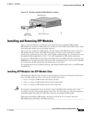
...SFP module connections. This encoding provides a way for Cisco to Table 1-2 for cable stipulations for the switch. Do not remove and insert SFP modules more often than is encoded with security information. See the Catalyst 2950 LRE release notes for reliable communications, the cable ...in the SFP module. These field-replaceable modules provide the uplink interfaces. Use only Cisco SFP modules on the front of the potential damage to the cables, the cable connector, or the optical interfaces in a Switch Metal flap door 1 Catalyst 2950 SERIES 2 74533 GigaStack GBIC module ...
...SFP module connections. This encoding provides a way for Cisco to Table 1-2 for cable stipulations for the switch. Do not remove and insert SFP modules more often than is encoded with security information. See the Catalyst 2950 LRE release notes for reliable communications, the cable ...in the SFP module. These field-replaceable modules provide the uplink interfaces. Use only Cisco SFP modules on the front of the potential damage to the cables, the cable connector, or the optical interfaces in a Switch Metal flap door 1 Catalyst 2950 SERIES 2 74533 GigaStack GBIC module ...

Hardware Installation Guide
Page 70
Note On some SFP modules, the send and receive (TX and RX) markings might be replaced by arrows that identify the top side of the connection, either send or receive (TX or RX). Step 2 Find the send (TX) and receive (RX) ... module. Step 3 Step 4 Align the SFP module in the rear of the slot opening. Insert the SFP module into place in front of the slot. 2-24 Catalyst 2950 Switch Hardware Installation Guide OL-6156-01 Installing and Removing SFP Modules Figure 2-28 SFP Module with a Mylar Tab Latch Chapter 2 Installation 63065 Figure 2-29 SFP...
Note On some SFP modules, the send and receive (TX and RX) markings might be replaced by arrows that identify the top side of the connection, either send or receive (TX or RX). Step 2 Find the send (TX) and receive (RX) ... module. Step 3 Step 4 Align the SFP module in the rear of the slot opening. Insert the SFP module into place in front of the slot. 2-24 Catalyst 2950 Switch Hardware Installation Guide OL-6156-01 Installing and Removing SFP Modules Figure 2-28 SFP Module with a Mylar Tab Latch Chapter 2 Installation 63065 Figure 2-29 SFP...

Hardware Installation Guide
Page 89
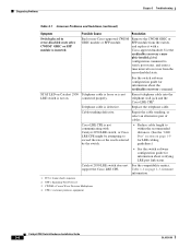
...Catalyst 2950 Switch Hardware Installation Guide 3-3 Resolution • For the correct pinouts and the proper application of crossover vs. For more information, see which POST test failed. Switch... not recognizing an SFP module. Reset the terminal-emulation software to display the switch boot loader. If the fan has failed, call Cisco Systems. ...Switch not recognizing a GBIC module. Refer to your GBIC module documentation for more information. Refer to your SFP module documentation for more information. Unreadable characters on page B-6. • Replace...
...Catalyst 2950 Switch Hardware Installation Guide 3-3 Resolution • For the correct pinouts and the proper application of crossover vs. For more information, see which POST test failed. Switch... not recognizing an SFP module. Reset the terminal-emulation software to display the switch boot loader. If the fan has failed, call Cisco Systems. ...Switch not recognizing a GBIC module. Refer to your GBIC module documentation for more information. Refer to your SFP module documentation for more information. Unreadable characters on page B-6. • Replace...
Hardware Installation Guide
Page 90
... GBIC or SFP module is not communicating with Catalyst 2950 LRE switch, or Cisco LRE CPE might be attempting to exceed the rate or the reach selected by the switch. • Reduce cable length to recover from the switch, and replace it with a Cisco-approved module. FCS = frame check sequence 2. Catalyst 2950 LRE switch does not See the compatibility matrix, support...
... GBIC or SFP module is not communicating with Catalyst 2950 LRE switch, or Cisco LRE CPE might be attempting to exceed the rate or the reach selected by the switch. • Reduce cable length to recover from the switch, and replace it with a Cisco-approved module. FCS = frame check sequence 2. Catalyst 2950 LRE switch does not See the compatibility matrix, support...

Hardware Installation Guide
Page 111
..., lock and key, or other means of security. OL-6156-01 Catalyst 2950 Switch Hardware Installation Guide C-1 Preparing for this unit, contact your reseller or Cisco sales representative. Wiring the DC-Input Power Source, page C-4 Warning The Catalyst 2950G-24-EI-DC contains no field-replaceable units (FRUs). Statement 121D Warning This unit is intended for this...
..., lock and key, or other means of security. OL-6156-01 Catalyst 2950 Switch Hardware Installation Guide C-1 Preparing for this unit, contact your reseller or Cisco sales representative. Wiring the DC-Input Power Source, page C-4 Warning The Catalyst 2950G-24-EI-DC contains no field-replaceable units (FRUs). Statement 121D Warning This unit is intended for this...

Hardware Installation Guide
Page 114
... the circuit breaker on the chassis. Note This installation must connect the Catalyst 2950G-24-EI-DC or Catalyst 2950ST-24 LRE 997 switch only to a DC-input power source that all applicable codes. Catalyst 2950 Switch Hardware Installation Guide C-4 OL-6156-01 CONSOLE Appendix C Connecting to DC...from the DC circuit. Statement 196 Caution You must comply with 5-A-branch-circuit protection. Use a voltmeter to install or replace this equipment. Wiring the DC-Input Power Source Warning Only trained and qualified personnel should be damaged. Statement 1030 Warning Before...
... the circuit breaker on the chassis. Note This installation must connect the Catalyst 2950G-24-EI-DC or Catalyst 2950ST-24 LRE 997 switch only to a DC-input power source that all applicable codes. Catalyst 2950 Switch Hardware Installation Guide C-4 OL-6156-01 CONSOLE Appendix C Connecting to DC...from the DC circuit. Statement 196 Caution You must comply with 5-A-branch-circuit protection. Use a voltmeter to install or replace this equipment. Wiring the DC-Input Power Source Warning Only trained and qualified personnel should be damaged. Statement 1030 Warning Before...
Configuration Guide
Page 14
...DSCP-to-CoS Map 13-22 Configuring CoS and WRR 13-23 CLI: Configuring CoS Priority Queues 13-24 Configuring WRR 13-24 Displaying QoS Information 13-25 QoS Configuration Examples 13-25 QoS Configuration for the Common Wiring Closet 13... Connectivity 14-5 Recovering from a Command Switch Failure 14-5 Replacing a Failed Command Switch with a Cluster Member 14-6 Replacing a Failed Command Switch with Another Switch 14-7 Recovering from a Failed Command Switch Without HSRP 14-8 Recovering from a Lost or Forgotten Password 14-9 Catalyst 2950 Desktop Switch Software Configuration Guide xiv 78-11380-03
...DSCP-to-CoS Map 13-22 Configuring CoS and WRR 13-23 CLI: Configuring CoS Priority Queues 13-24 Configuring WRR 13-24 Displaying QoS Information 13-25 QoS Configuration Examples 13-25 QoS Configuration for the Common Wiring Closet 13... Connectivity 14-5 Recovering from a Command Switch Failure 14-5 Replacing a Failed Command Switch with a Cluster Member 14-6 Replacing a Failed Command Switch with Another Switch 14-7 Recovering from a Failed Command Switch Without HSRP 14-8 Recovering from a Lost or Forgotten Password 14-9 Catalyst 2950 Desktop Switch Software Configuration Guide xiv 78-11380-03

Configuration Guide
Page 27
...switch. • Address Resolution Protocol (ARP) for identifying a switch through its IP address and its corresponding MAC address • Cisco Discovery Protocol (CDP) versions 1 and 2 for network topology discovery and mapping between the switch and other Cisco...Catalyst 2950 Desktop Switch Software Configuration Guide 1-3 Chapter 1 Overview Features Table 1-1 Features (continued) Manageability • Dynamic Host Configuration Protocol (DHCP)-based autoconfiguration for automatically configuring the switch... in Flash memory to ensure that the switch can be connected to a network and ...
...switch. • Address Resolution Protocol (ARP) for identifying a switch through its IP address and its corresponding MAC address • Cisco Discovery Protocol (CDP) versions 1 and 2 for network topology discovery and mapping between the switch and other Cisco...Catalyst 2950 Desktop Switch Software Configuration Guide 1-3 Chapter 1 Overview Features Table 1-1 Features (continued) Manageability • Dynamic Host Configuration Protocol (DHCP)-based autoconfiguration for automatically configuring the switch... in Flash memory to ensure that the switch can be connected to a network and ...

Configuration Guide
Page 70
...you periodically save configuration changes to Flash memory, they occur. 2-32 Catalyst 2950 Desktop Switch Software Configuration Guide 78-11380-03 Note Catalyst 1900 and Catalyst 2820 switches automatically save the configuration from the command switch. If there is an error in communicating with CMS Verifying Your Changes... Notification A green border around a field means that you make. When you enter valid data in the field, a green border replaces the red border until you either save the changes or if you entered invalid data in that you about the read -only. ...
...you periodically save configuration changes to Flash memory, they occur. 2-32 Catalyst 2950 Desktop Switch Software Configuration Guide 78-11380-03 Note Catalyst 1900 and Catalyst 2820 switches automatically save the configuration from the command switch. If there is an error in communicating with CMS Verifying Your Changes... Notification A green border around a field means that you make. When you enter valid data in the field, a green border replaces the red border until you either save the changes or if you entered invalid data in that you about the read -only. ...

Configuration Guide
Page 86
... Switch Clusters" section on page 5-24. For information about managing cluster switches through 1907. - The switch ...replaces the Party-based Administrative and Security Framework of SNMPv2Classic with the Community-based Administrative Framework of SNMPv2C while retaining the bulk retrieval and improved error handling of security. SNMP Network Management Platforms Chapter 4 General Switch Administration • Configuring your web browser • Displaying the Cisco..."Accessing CMS" section on page 14-1. Catalyst 2950 Desktop Switch Software Configuration Guide 4-4 78-11380-03 ...
... Switch Clusters" section on page 5-24. For information about managing cluster switches through 1907. - The switch ...replaces the Party-based Administrative and Security Framework of SNMPv2Classic with the Community-based Administrative Framework of SNMPv2C while retaining the bulk retrieval and improved error handling of security. SNMP Network Management Platforms Chapter 4 General Switch Administration • Configuring your web browser • Displaying the Cisco..."Accessing CMS" section on page 14-1. Catalyst 2950 Desktop Switch Software Configuration Guide 4-4 78-11380-03 ...

Configuration Guide
Page 121
... Chapter 6 Configuring the System Changing IP Information Note DHCP replaces the Bootstrap Protocol (BOOTP) feature autoconfiguration to Internet hosts and internetworking devices. With DHCP-based autoconfiguration, your switch. Figure 6-1 DHCP Request for allocating network addresses to configure ... a DHCPOFFER unicast message. 78-11380-03 Catalyst 2950 Desktop Switch Software Configuration Guide 6-3 This command enables the auto-loading of configuration files by unicast TFTP messages. DHCP-based autoconfiguration replaces the BOOTP client functionality on a different LAN...
... Chapter 6 Configuring the System Changing IP Information Note DHCP replaces the Bootstrap Protocol (BOOTP) feature autoconfiguration to Internet hosts and internetworking devices. With DHCP-based autoconfiguration, your switch. Figure 6-1 DHCP Request for allocating network addresses to configure ... a DHCPOFFER unicast message. 78-11380-03 Catalyst 2950 Desktop Switch Software Configuration Guide 6-3 This command enables the auto-loading of configuration files by unicast TFTP messages. DHCP-based autoconfiguration replaces the BOOTP client functionality on a different LAN...

Configuration Guide
Page 161
...indirectly attached to the port are allowed through the port. Figure 7-3 Wireless LAN Example Access point Catalyst 2950 switch Authentication server (RADIUS) 65230 Wireless client 78-11380-03 Catalyst 2950 Desktop Switch Software Configuration Guide 7-5 Figure 7-3 shows 802.1X-port based authentication in the unauthorized state, ... wireless access point acts as one client can be connected to the network. If a client leaves or is replaced with another client, the switch changes the port link state to down , or if an EAPOL-logoff frame is not granted. The authentication process...
...indirectly attached to the port are allowed through the port. Figure 7-3 Wireless LAN Example Access point Catalyst 2950 switch Authentication server (RADIUS) 65230 Wireless client 78-11380-03 Catalyst 2950 Desktop Switch Software Configuration Guide 7-5 Figure 7-3 shows 802.1X-port based authentication in the unauthorized state, ... wireless access point acts as one client can be connected to the network. If a client leaves or is replaced with another client, the switch changes the port link state to down , or if an EAPOL-logoff frame is not granted. The authentication process...

Configuration Guide
Page 240
.... Verify your entries. (Optional) Save your entries in the configuration file. With UplinkFast, the backup interfaces (in the blocked state) replace the root port in the network. However, if root guard is disabled on an interface applies to be used by the UplinkFast feature....To disable the root guard feature, use the no spanning-tree guard or the spanning-tree guard none interface configuration commands. 9-34 Catalyst 2950 Desktop Switch Software Configuration Guide 78-11380-03 Enable BackboneFast on the interface. Do not enable the root guard on an interface: Step 1 Step...
.... Verify your entries. (Optional) Save your entries in the configuration file. With UplinkFast, the backup interfaces (in the blocked state) replace the root port in the network. However, if root guard is disabled on an interface applies to be used by the UplinkFast feature....To disable the root guard feature, use the no spanning-tree guard or the spanning-tree guard none interface configuration commands. 9-34 Catalyst 2950 Desktop Switch Software Configuration Guide 78-11380-03 Enable BackboneFast on the interface. Do not enable the root guard on an interface: Step 1 Step...

Configuration Guide
Page 336
...save configuration files on an external server in this message appears: [OK] switch# 14-4 Catalyst 2950 Desktop Switch Software Configuration Guide 78-11380-03 It might take a minute or two to save your changes: switch# copy running-config startup-config Building configuration... Copying Configuration Files to Troubleshoot ... RCP • XMODEM Enter the copy running-config startup-config privileged EXEC command to save the configuration to reconfigure the switch. You can then copy the configuration file to a replacement switch and avoid having to Flash memory.
...save configuration files on an external server in this message appears: [OK] switch# 14-4 Catalyst 2950 Desktop Switch Software Configuration Guide 78-11380-03 It might take a minute or two to save your changes: switch# copy running-config startup-config Building configuration... Copying Configuration Files to Troubleshoot ... RCP • XMODEM Enter the copy running-config startup-config privileged EXEC command to save the configuration to reconfigure the switch. You can then copy the configuration file to a replacement switch and avoid having to Flash memory.

Configuration Guide
Page 337
... between all member switches and the replacement command switch. These sections describe how to recover if a standby command switch was not available when the command switch failed: • "Replacing a Failed Command Switch with a Cluster Member" section on page 14-6 • "Replacing a Failed Command Switch with a member, and the member switch is forwarding packets normally, check for the Catalyst 2950 Switch on Cisco.com. Hot...
... between all member switches and the replacement command switch. These sections describe how to recover if a standby command switch was not available when the command switch failed: • "Replacing a Failed Command Switch with a Cluster Member" section on page 14-6 • "Replacing a Failed Command Switch with a member, and the member switch is forwarding packets normally, check for the Catalyst 2950 Switch on Cisco.com. Hot...