
Hardware Installation Guide
Page 4
...23 Cisco RPS Connector 1-23 Console Port 1-24 Management Options 1-24 Installation 2-1 Preparing for Installation 2-1 Warnings 2-1 Installation Guidelines 2-4 Verifying Package Contents 2-5 Verifying Switch Operation 2-6 Installing the Switch 2-7 Installing the Switch in a Rack 2-7 Attaching the Brackets to the Switch 2-8 Mounting the Switch ...Switch on a Table, Shelf, or Desk 2-17 Installing the Switch on a Wall 2-17 Attaching the Brackets to the Switch 2-17 Attaching the RPS Connector Cover 2-18 Mounting the Switch to a Wall 2-18 Installing the Optional AC Ground Kit for Catalyst 2950 Switches...
...23 Cisco RPS Connector 1-23 Console Port 1-24 Management Options 1-24 Installation 2-1 Preparing for Installation 2-1 Warnings 2-1 Installation Guidelines 2-4 Verifying Package Contents 2-5 Verifying Switch Operation 2-6 Installing the Switch 2-7 Installing the Switch in a Rack 2-7 Attaching the Brackets to the Switch 2-8 Mounting the Switch ...Switch on a Table, Shelf, or Desk 2-17 Installing the Switch on a Wall 2-17 Attaching the Brackets to the Switch 2-17 Attaching the RPS Connector Cover 2-18 Mounting the Switch to a Wall 2-18 Installing the Optional AC Ground Kit for Catalyst 2950 Switches...
Hardware Installation Guide
Page 18
...your business operations running smoothly. Accessing all customers, partners, resellers, and distributors who hold valid Cisco service contracts, the Cisco Technical Assistance Center (TAC) provides 24-hour, award-winning technical support services, online and over the phone. For P1 or P2...the TAC Case Open Tool automatically recommends resources for an immediate solution. xviii Catalyst 2950 Switch Hardware Installation Guide OL-6156-01 Cisco TAC Website The Cisco TAC website (http://www.cisco.com/tac) provides online documents and tools for technical assistance. After you ...
...your business operations running smoothly. Accessing all customers, partners, resellers, and distributors who hold valid Cisco service contracts, the Cisco Technical Assistance Center (TAC) provides 24-hour, award-winning technical support services, online and over the phone. For P1 or P2...the TAC Case Open Tool automatically recommends resources for an immediate solution. xviii Catalyst 2950 Switch Hardware Installation Guide OL-6156-01 Cisco TAC Website The Cisco TAC website (http://www.cisco.com/tac) provides online documents and tools for technical assistance. After you ...
Hardware Installation Guide
Page 21
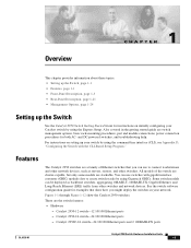
... models of Ethernet switches that show the Catalyst 2950 switches. Catalyst 2950-12 switch-12 10/100 Ethernet ports - You can be deployed as servers, routers, and other switches and network devices. Figure 1-1 through Figure 1-12 show how you can use switches with the CLI-Based Setup Program." See the switch software configuration guide for both AC- Catalyst 2950C-24 switch-24 10/100...
... models of Ethernet switches that show the Catalyst 2950 switches. Catalyst 2950-12 switch-12 10/100 Ethernet ports - You can be deployed as servers, routers, and other switches and network devices. Figure 1-1 through Figure 1-12 show how you can use switches with the CLI-Based Setup Program." See the switch software configuration guide for both AC- Catalyst 2950C-24 switch-24 10/100...

Hardware Installation Guide
Page 22
...and duplex settings - Supports 8192 MAC addresses - Checks for the Catalyst 2950 LRE switches. - Catalyst 2950G-12-EI-12 10/100 Ethernet ports and 2 GBIC module slots - On Catalyst 2950G-12-EI, 2950G-24-EI, 2950G-24-EI-DC, and 2950G-48-EI switches, support for a list of the four uplink ports are active ...a received packet, determines the destination port, stores the packet in shared memory, and then forwards the packet to the destination port Catalyst 2950 Switch Hardware Installation Guide 1-2 OL-6156-01 Catalyst 2950SX-24 switch-24 10/100 Ethernet ports and 2 1000BASE-SX ports -
...and duplex settings - Supports 8192 MAC addresses - Checks for the Catalyst 2950 LRE switches. - Catalyst 2950G-12-EI-12 10/100 Ethernet ports and 2 GBIC module slots - On Catalyst 2950G-12-EI, 2950G-24-EI, 2950G-24-EI-DC, and 2950G-48-EI switches, support for a list of the four uplink ports are active ...a received packet, determines the destination port, stores the packet in shared memory, and then forwards the packet to the destination port Catalyst 2950 Switch Hardware Installation Guide 1-2 OL-6156-01 Catalyst 2950SX-24 switch-24 10/100 Ethernet ports and 2 1000BASE-SX ports -

Hardware Installation Guide
Page 23
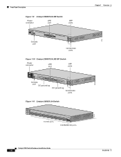
... ports Catalyst 2950 SERIES OL-6156-01 Catalyst 2950 Switch Hardware Installation Guide 1-3 Figure 1-1 to as the terminal block header), a DC ground lug, and an RJ-45 console port. Table 1-1 LRE Switch and CPE Compatibility Matrix LRE Devices Catalyst 2950ST-8 LRE Cisco 575 LRE Yes CPE Cisco 576 LRE 997 No CPE Cisco 585 LRE Yes CPE Catalyst 2950ST-24 LRE Catalyst 2950ST-24...
... ports Catalyst 2950 SERIES OL-6156-01 Catalyst 2950 Switch Hardware Installation Guide 1-3 Figure 1-1 to as the terminal block header), a DC ground lug, and an RJ-45 console port. Table 1-1 LRE Switch and CPE Compatibility Matrix LRE Devices Catalyst 2950ST-8 LRE Cisco 575 LRE Yes CPE Cisco 576 LRE 997 No CPE Cisco 585 LRE Yes CPE Catalyst 2950ST-24 LRE Catalyst 2950ST-24...

Hardware Installation Guide
Page 24
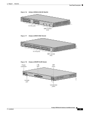
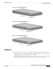
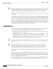
... 5x 6x 7x 8x 9x 10x 11x 10Base-T / 100Base-TX 12x 13x 14x 15x 16x 17x 18x 19x 20x 21x 22x 23x Catalyst 2950 SERIES 24x 10/100 ports Figure 1-3 Catalyst 2950C-24 Switch SYST RPS STAT UTIL DUPLX SPEED MODE 1x 2x 3x 4x 5x 6x 7x 8x 9x 10x 11x 10BASE-T / 100BASE-TX... RPS STAT UTIL DUPLX SPEED MODE 1 1X 23 45 67 8 9 10 11 12 11X 2X 12X 10/100 ports 1 Catalyst 2950 SERIES 2 GBIC module slots Figure 1-5 Catalyst 2950G-24-EI Switch SYST RPS STAT UTIL DUPLX SPEED MODE 1 1X 23 45 67 8 9 10 11 12 11X 2X 12X 13 13X 14 15 16 17 18...
... 5x 6x 7x 8x 9x 10x 11x 10Base-T / 100Base-TX 12x 13x 14x 15x 16x 17x 18x 19x 20x 21x 22x 23x Catalyst 2950 SERIES 24x 10/100 ports Figure 1-3 Catalyst 2950C-24 Switch SYST RPS STAT UTIL DUPLX SPEED MODE 1x 2x 3x 4x 5x 6x 7x 8x 9x 10x 11x 10BASE-T / 100BASE-TX... RPS STAT UTIL DUPLX SPEED MODE 1 1X 23 45 67 8 9 10 11 12 11X 2X 12X 10/100 ports 1 Catalyst 2950 SERIES 2 GBIC module slots Figure 1-5 Catalyst 2950G-24-EI Switch SYST RPS STAT UTIL DUPLX SPEED MODE 1 1X 23 45 67 8 9 10 11 12 11X 2X 12X 13 13X 14 15 16 17 18...
Hardware Installation Guide
Page 25
... 8 9 10 11 12 11X 2X 12X 13X 13 14 15 16 17 18 19 20 21 22 23 24 23X 14X 24X 10/100 ports 1 Catalyst 2950 SERIES 2 GBIC module slots Figure 1-7 Catalyst 2950G-48-EI Switch SYST RPS STAT UTIL DUPLX SPEED MODE 1 1X 2X 23 45 67 8 9 10 11 12 13 14 15... 16 17 15X 17X 18 19 20 21 22 23 24 25 26 27 28 29 30 31 32 16X...
... 8 9 10 11 12 11X 2X 12X 13X 13 14 15 16 17 18 19 20 21 22 23 24 23X 14X 24X 10/100 ports 1 Catalyst 2950 SERIES 2 GBIC module slots Figure 1-7 Catalyst 2950G-48-EI Switch SYST RPS STAT UTIL DUPLX SPEED MODE 1 1X 2X 23 45 67 8 9 10 11 12 13 14 15... 16 17 15X 17X 18 19 20 21 22 23 24 25 26 27 28 29 30 31 32 16X...
Hardware Installation Guide
Page 26
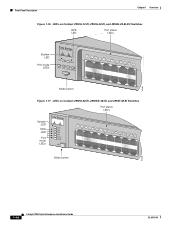
... DC ground lug 13 14 15 16 17 18 19 20 21 22 23 24 Catalyst 2950 SERIES LRE 997 1 2 1 2 DC ground lug 10/100/1000 ports Figure 1-11 Catalyst 2950SX-24 Switch SYST RPS STAT UTIL DUPLX SPEED MODE 1x 2x 3x 4x 5x 6x 7x... 24x 1000BASE-SX 25 26 10/100 ports 1000BASE-SX ports 74516 89363 81184 Chapter 1 Overview Catalyst 2950 Switch Hardware Installation Guide 1-6 OL-6156-01 Front-Panel Description Figure 1-9 Catalyst 2950ST-24 LRE Switch Power LRE connector port SFP ports 110.00A-1/02R.75A/TA2I0N500G--26400HVZ~ MODE SYST RPS STAT SPEED CONSOLE 1 2 3 ...
... DC ground lug 13 14 15 16 17 18 19 20 21 22 23 24 Catalyst 2950 SERIES LRE 997 1 2 1 2 DC ground lug 10/100/1000 ports Figure 1-11 Catalyst 2950SX-24 Switch SYST RPS STAT UTIL DUPLX SPEED MODE 1x 2x 3x 4x 5x 6x 7x... 24x 1000BASE-SX 25 26 10/100 ports 1000BASE-SX ports 74516 89363 81184 Chapter 1 Overview Catalyst 2950 Switch Hardware Installation Guide 1-6 OL-6156-01 Front-Panel Description Figure 1-9 Catalyst 2950ST-24 LRE Switch Power LRE connector port SFP ports 110.00A-1/02R.75A/TA2I0N500G--26400HVZ~ MODE SYST RPS STAT SPEED CONSOLE 1 2 3 ...
Hardware Installation Guide
Page 27
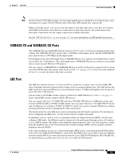
...standard RJ-45 connectors and two twisted-pair cabling. OL-6156-01 Catalyst 2950 Switch Hardware Installation Guide 1-7 The ports can use RJ-45 connectors and twisted-pair cabling. Chapter 1 Overview Figure 1-12 Catalyst 2950T-24 Switch Front-Panel Description 47337 SYST RPS STAT UTIL DUPLX SPEED MODE 1x... 2x 3x 4x 5x 6x 7x 8x 9x 10x 11x 10Base-T / 100Base-TX 12x 13x 14x 15x 16x 17x 18x 19x 20x 21x 22x 23x Catalyst 2950 SERIES 24x 10/100/...
...standard RJ-45 connectors and two twisted-pair cabling. OL-6156-01 Catalyst 2950 Switch Hardware Installation Guide 1-7 The ports can use RJ-45 connectors and twisted-pair cabling. Chapter 1 Overview Figure 1-12 Catalyst 2950T-24 Switch Front-Panel Description 47337 SYST RPS STAT UTIL DUPLX SPEED MODE 1x... 2x 3x 4x 5x 6x 7x 8x 9x 10x 11x 10Base-T / 100Base-TX 12x 13x 14x 15x 16x 17x 18x 19x 20x 21x 22x 23x Catalyst 2950 SERIES 24x 10/100/...
Hardware Installation Guide
Page 28
... crossover cable, go to the "Identifying a Crossover Cable" section on page B-5. The 10/100/1000 ports on Catalyst 2950T-24, Catalyst 2950T-48-SI, and Catalyst 2950 LRE switches use a twisted-pair straight-through cable. The 10/100 ports can be explicitly set to operate in full-duplex ...mode. Front-Panel Description Chapter 1 Overview Note When connecting the switch to workstations, servers, and routers, be sure ...
... crossover cable, go to the "Identifying a Crossover Cable" section on page B-5. The 10/100/1000 ports on Catalyst 2950T-24, Catalyst 2950T-48-SI, and Catalyst 2950 LRE switches use a twisted-pair straight-through cable. The 10/100 ports can be explicitly set to operate in full-duplex ...mode. Front-Panel Description Chapter 1 Overview Note When connecting the switch to workstations, servers, and routers, be sure ...
Hardware Installation Guide
Page 29
... to LRE ports on page 1-3 shows which LRE switches support which CPE devices. The default mode for the Cisco LRE 48 POTS Splitter. For more information on a switch to 24 Cisco LRE CPE devices through structured or unstructured wiring, such as existing telephone lines. If a Catalyst 2950 LRE switch senses more than two connections for more information about...
... to LRE ports on page 1-3 shows which LRE switches support which CPE devices. The default mode for the Cisco LRE 48 POTS Splitter. For more information on a switch to 24 Cisco LRE CPE devices through structured or unstructured wiring, such as existing telephone lines. If a Catalyst 2950 LRE switch senses more than two connections for more information about...

Hardware Installation Guide
Page 33
... Catalyst 2950-12, 2950-24, 2950C-24, 2950SX-24, and 2950T-24 switches • Figure 1-16 for the Catalyst 2950G-12-EI, 2950G-24-EI, and 2950G-24-EI-DC switches • Figure 1-17 for the Catalyst 2950G-48-EI, Catalyst 2950SX-48-SI, and Catalyst 2950T-48-SI switches • Figure 1-18 for the Catalyst 2950ST-8 LRE and 2950ST-24 LRE switches • Figure 1-19 for the Catalyst 2950ST-24...
... Catalyst 2950-12, 2950-24, 2950C-24, 2950SX-24, and 2950T-24 switches • Figure 1-16 for the Catalyst 2950G-12-EI, 2950G-24-EI, and 2950G-24-EI-DC switches • Figure 1-17 for the Catalyst 2950G-48-EI, Catalyst 2950SX-48-SI, and Catalyst 2950T-48-SI switches • Figure 1-18 for the Catalyst 2950ST-8 LRE and 2950ST-24 LRE switches • Figure 1-19 for the Catalyst 2950ST-24...
Hardware Installation Guide
Page 34
Front-Panel Description Chapter 1 Overview Figure 1-16 LEDs on Catalyst 2950G-12-EI, 2950G-24-EI, and 2950G-24-EI-DC Switches RPS LED Port status LEDs 65395 System LED Port mode LEDs SYST RPS STAT UTIL DUPLX SPEED MODE 1 1X 23 45 67 8 9 10 11 12 ...-EI, 2950SX-48-SI, and 2950T-48-SI Switches Port status LEDs System LED RPS LED Port mode LEDs SYST RPS STAT UTIL DUPLX SPEED MODE 1 1X 23 45 67 89 10 11 12 13 14 15 16 15X 2X 16X Mode button 65508 1-14 Catalyst 2950 Switch Hardware Installation Guide OL-6156-01
Front-Panel Description Chapter 1 Overview Figure 1-16 LEDs on Catalyst 2950G-12-EI, 2950G-24-EI, and 2950G-24-EI-DC Switches RPS LED Port status LEDs 65395 System LED Port mode LEDs SYST RPS STAT UTIL DUPLX SPEED MODE 1 1X 23 45 67 8 9 10 11 12 ...-EI, 2950SX-48-SI, and 2950T-48-SI Switches Port status LEDs System LED RPS LED Port mode LEDs SYST RPS STAT UTIL DUPLX SPEED MODE 1 1X 23 45 67 89 10 11 12 13 14 15 16 15X 2X 16X Mode button 65508 1-14 Catalyst 2950 Switch Hardware Installation Guide OL-6156-01

Hardware Installation Guide
Page 35
... 81187 110.00A-1/02R.75A/TA2I0N500G--26400HVZ~ MODE SYST RPS STAT SPEED CONSOLE 1 2 3 4 5 6 7 8 Mode button Speed LED STAT LED Figure 1-19 LEDs on Catalyst 2950ST-24 LRE 997 Switches System LED Redundant power system LED Port status LEDs -- ++ A INPCUUTR:RE3N6T- B 72 V :2-1 A SYST RPS STAT SPEED MODE CONSOLE STAT LED Speed Mode LED button...
... 81187 110.00A-1/02R.75A/TA2I0N500G--26400HVZ~ MODE SYST RPS STAT SPEED CONSOLE 1 2 3 4 5 6 7 8 Mode button Speed LED STAT LED Figure 1-19 LEDs on Catalyst 2950ST-24 LRE 997 Switches System LED Redundant power system LED Port status LEDs -- ++ A INPCUUTR:RE3N6T- B 72 V :2-1 A SYST RPS STAT SPEED MODE CONSOLE STAT LED Speed Mode LED button...

Hardware Installation Guide
Page 37
...The current backplane utilization that is set to interpret the colors for the non-LRE switches. Green and amber See Figure 1-20 to interpret these colors for the LRE switches. Table 1-6 explains how to Figure 1-24 for a link-fault indication. The port LEDs are monitored for details. Port ...Mbps for 10/100 ports and 10, 100, or 1000 Mbps for Non-LRE Switches Port Mode Color Meaning STAT (port status) Off No link. Table 1-6 Meaning of the port LED colors change. A Catalyst 2950 LRE switch does not have a UTIL or a DUPLX LED. Alternating green-amber Link fault....
...The current backplane utilization that is set to interpret the colors for the non-LRE switches. Green and amber See Figure 1-20 to interpret these colors for the LRE switches. Table 1-6 explains how to Figure 1-24 for a link-fault indication. The port LEDs are monitored for details. Port ...Mbps for 10/100 ports and 10, 100, or 1000 Mbps for Non-LRE Switches Port Mode Color Meaning STAT (port status) Off No link. Table 1-6 Meaning of the port LED colors change. A Catalyst 2950 LRE switch does not have a UTIL or a DUPLX LED. Alternating green-amber Link fault....
Hardware Installation Guide
Page 39
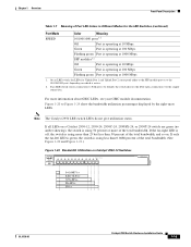
.... If only the far-left LED is green, the switch is using less than 50 percent of the total bandwidth, and so on a Catalyst 2950-12, 2950-24, 2950C-24, 2950SX-24, or 2950T-24 switch are green (no amber showing), the switch is using more than 25 but less than 0.0488 percent...SPEED MODE 1x 2x 3x 4x 5x 6x 7x 8x 10Base-T / 100Base-TX 9x 10x 11x 12x Catalyst 2950 SERIES 47267 0-0.0487%+ 6.25-12.4%+ 12.5-24%+ 25-49%+ 50%+ OL-6156-01 Catalyst 2950 Switch Hardware Installation Guide 1-19 Chapter 1 Overview Front-Panel Description Table 1-7 Meaning of the total bandwidth. ...
.... If only the far-left LED is green, the switch is using less than 50 percent of the total bandwidth, and so on a Catalyst 2950-12, 2950-24, 2950C-24, 2950SX-24, or 2950T-24 switch are green (no amber showing), the switch is using more than 25 but less than 0.0488 percent...SPEED MODE 1x 2x 3x 4x 5x 6x 7x 8x 10Base-T / 100Base-TX 9x 10x 11x 12x Catalyst 2950 SERIES 47267 0-0.0487%+ 6.25-12.4%+ 12.5-24%+ 25-49%+ 50%+ OL-6156-01 Catalyst 2950 Switch Hardware Installation Guide 1-19 Chapter 1 Overview Front-Panel Description Table 1-7 Meaning of the total bandwidth. ...
Hardware Installation Guide
Page 40
...than 25 but less than 50 percent of the total bandwidth. Front-Panel Description Chapter 1 Overview Figure 1-21 Bandwidth Utilization on Catalyst 2950-24, 2950C-24, 2950SX-24, and 2950T-24 Switches SYST RPS STAT UTIL DUPLX SPEED MODE 1x 2x 3x 4x 5x 6x 7x 8x 10Base-T / 100Base-TX 9x 10x 11x ...15X 1 STAT UTIL DUPLX SPEED 2X 12X 14X 16X MODE < 25% + 25% - 49% + 50% + Catalyst 2950 2 If all LEDs on a Catalyst 2950G-24-EI or 2950G-24-EI-DC switch are green, the switch is using more than 25 but less than 25 percent of the total bandwidth, and so on. (See Figure...
...than 25 but less than 50 percent of the total bandwidth. Front-Panel Description Chapter 1 Overview Figure 1-21 Bandwidth Utilization on Catalyst 2950-24, 2950C-24, 2950SX-24, and 2950T-24 Switches SYST RPS STAT UTIL DUPLX SPEED MODE 1x 2x 3x 4x 5x 6x 7x 8x 10Base-T / 100Base-TX 9x 10x 11x ...15X 1 STAT UTIL DUPLX SPEED 2X 12X 14X 16X MODE < 25% + 25% - 49% + 50% + Catalyst 2950 2 If all LEDs on a Catalyst 2950G-24-EI or 2950G-24-EI-DC switch are green, the switch is using more than 25 but less than 25 percent of the total bandwidth, and so on. (See Figure...

Hardware Installation Guide
Page 41
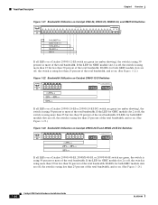
... power connector [email protected]. Chapter 1 Overview Rear-Panel Description Figure 1-24 Bandwidth Utilization on Catalyst 2950G-48-EI, 2950SX-48-SI, and 2950T-48-SI Switches 65510 Catalyst 2950 12 1X 3 24 56 78 9 10 11 12 13 14 15 16 15X 17 18 17X 19... 32X 34X 2 48X < 25% + 25% - 49% + 50% + Rear-Panel Description Other than the Catalyst 2950G-24-EI-DC switch and the Catalyst 2950 LRE switches, the rear panel of a Catalyst 2950 switch has an AC power connector, an RPS connector, and an RJ-45 console port. (See Figure 1-25 and Figure...
... power connector [email protected]. Chapter 1 Overview Rear-Panel Description Figure 1-24 Bandwidth Utilization on Catalyst 2950G-48-EI, 2950SX-48-SI, and 2950T-48-SI Switches 65510 Catalyst 2950 12 1X 3 24 56 78 9 10 11 12 13 14 15 16 15X 17 18 17X 19... 32X 34X 2 48X < 25% + 25% - 49% + 50% + Rear-Panel Description Other than the Catalyst 2950G-24-EI-DC switch and the Catalyst 2950 LRE switches, the rear panel of a Catalyst 2950 switch has an AC power connector, an RPS connector, and an RJ-45 console port. (See Figure 1-25 and Figure...

Hardware Installation Guide
Page 42
...-8 LRE Switch, Catalyst 2950ST-24 LRE, and Catalyst 2950ST-24 LRE 997 Switch Rear Panel RPS Fans connector 81225 Power Connectors You can order these L-shaped AC power cords from your Cisco sales representative: • CAB-NP1200-AC-AR= • CAB-NP1200-AC-AU= • CAB-NP1200-AC-CH= • CAB-NP1200-AC-EU= 1-22 Catalyst 2950 Switch Hardware Installation...
...-8 LRE Switch, Catalyst 2950ST-24 LRE, and Catalyst 2950ST-24 LRE 997 Switch Rear Panel RPS Fans connector 81225 Power Connectors You can order these L-shaped AC power cords from your Cisco sales representative: • CAB-NP1200-AC-AR= • CAB-NP1200-AC-AU= • CAB-NP1200-AC-CH= • CAB-NP1200-AC-EU= 1-22 Catalyst 2950 Switch Hardware Installation...

Hardware Installation Guide
Page 43
...AC-RPS-N1=) to the switch. OL-6156-01 Catalyst 2950 Switch Hardware Installation Guide 1-23 Cisco RPS Connector Specific Cisco RPS models support specific Catalyst 2950 switches: • Cisco RPS 300 (model PWR300-AC-RPS-N1) • Cisco RPS 675 (model PWR675-AC-RPS-N1=) Cisco RPS 300 The Cisco RPS 300 has two output ...can support six external network devices and provides DC power to -72 VDC. Caution You must connect the Catalyst 2950G-24-EI-DC and 2950ST-24 LRE 997 switches only to a DC-input power source that can support six external network devices and provides DC power to ...
...AC-RPS-N1=) to the switch. OL-6156-01 Catalyst 2950 Switch Hardware Installation Guide 1-23 Cisco RPS Connector Specific Cisco RPS models support specific Catalyst 2950 switches: • Cisco RPS 300 (model PWR300-AC-RPS-N1) • Cisco RPS 675 (model PWR675-AC-RPS-N1=) Cisco RPS 300 The Cisco RPS 300 has two output ...can support six external network devices and provides DC power to -72 VDC. Caution You must connect the Catalyst 2950G-24-EI-DC and 2950ST-24 LRE 997 switches only to a DC-input power source that can support six external network devices and provides DC power to ...
