
Hardware Installation Guide
Page 2
...more of Class B devices: The equipment described in the United States and certain other company. (0406R) Catalyst 2950 Switch Hardware Installation Guide Copyright © 2004 Cisco Systems, Inc. USERS MUST TAKE FULL RESPONSIBILITY FOR THEIR APPLICATION OF ANY PRODUCTS. The following information is..., EXPRESS OR IMPLIED. IF YOU ARE UNABLE TO LOCATE THE SOFTWARE LICENSE OR LIMITED WARRANTY, CONTACT YOUR CISCO REPRESENTATIVE FOR A COPY. THE SPECIFICATIONS AND INFORMATION REGARDING THE PRODUCTS IN THIS MANUAL ARE SUBJECT TO CHANGE WITHOUT NOTICE. and/or its peripheral devices...
...more of Class B devices: The equipment described in the United States and certain other company. (0406R) Catalyst 2950 Switch Hardware Installation Guide Copyright © 2004 Cisco Systems, Inc. USERS MUST TAKE FULL RESPONSIBILITY FOR THEIR APPLICATION OF ANY PRODUCTS. The following information is..., EXPRESS OR IMPLIED. IF YOU ARE UNABLE TO LOCATE THE SOFTWARE LICENSE OR LIMITED WARRANTY, CONTACT YOUR CISCO REPRESENTATIVE FOR A COPY. THE SPECIFICATIONS AND INFORMATION REGARDING THE PRODUCTS IN THIS MANUAL ARE SUBJECT TO CHANGE WITHOUT NOTICE. and/or its peripheral devices...

Hardware Installation Guide
Page 5
...-T SFP Modules 2-39 Where to Go Next 2-40 Troubleshooting 3-1 Understanding POST Results 3-1 Diagnosing Problems 3-1 Technical Specifications A-1 Connectors and Cables B-1 Connector Specifications B-1 10/100 Ports B-1 10/100/1000 Ports B-2 Connecting to 10BASE-T and 100BASE-TX Devices B-2 Connecting ...Cable and Adapter Specifications B-6 Two Twisted-Pair Cable Pinouts B-6 Four Twisted-Pair Cable Pinouts for 10/100 Ports B-7 Four Twisted-Pair Cable Pinouts for 1000BASE-T Ports B-8 RJ-21 Cable Pinouts B-8 Adapter Pinouts B-10 Contents OL-6156-01 Catalyst 2950 Switch Hardware Installation ...
...-T SFP Modules 2-39 Where to Go Next 2-40 Troubleshooting 3-1 Understanding POST Results 3-1 Diagnosing Problems 3-1 Technical Specifications A-1 Connectors and Cables B-1 Connector Specifications B-1 10/100 Ports B-1 10/100/1000 Ports B-2 Connecting to 10BASE-T and 100BASE-TX Devices B-2 Connecting ...Cable and Adapter Specifications B-6 Two Twisted-Pair Cable Pinouts B-6 Four Twisted-Pair Cable Pinouts for 10/100 Ports B-7 Four Twisted-Pair Cable Pinouts for 1000BASE-T Ports B-8 RJ-21 Cable Pinouts B-8 Adapter Pinouts B-10 Contents OL-6156-01 Catalyst 2950 Switch Hardware Installation ...

Hardware Installation Guide
Page 9
...line interface (CLI) commands that you might encounter. Notes, cautions, and warnings use by the switch. OL-6156-01 Catalyst 2950 Switch Hardware Installation Guide ix This guide does not describe how to materials not contained in this manual...computer technician responsible for installing a Catalyst 2950 switch, hereafter referred to install a switch, and provides troubleshooting information and specifications. Notes contain helpful suggestions or references to configure software features on your switch or describe the Catalyst 2950-specific system messages that have been ...
...line interface (CLI) commands that you might encounter. Notes, cautions, and warnings use by the switch. OL-6156-01 Catalyst 2950 Switch Hardware Installation Guide ix This guide does not describe how to materials not contained in this manual...computer technician responsible for installing a Catalyst 2950 switch, hereafter referred to install a switch, and provides troubleshooting information and specifications. Notes contain helpful suggestions or references to configure software features on your switch or describe the Catalyst 2950-specific system messages that have been ...

Hardware Installation Guide
Page 31
... other. See the Catalyst 2950 LRE switch release notes for the list of a copper 10/100/1000 port and a fiber-optic SFP module slot. SFP Modules The LRE switches use Category 5 cable with LC or MT-RJ connectors to connect to 328 feet (100 meters). • Table 1-2 lists the cable specifications for reliable communications, the...
... other. See the Catalyst 2950 LRE switch release notes for the list of a copper 10/100/1000 port and a fiber-optic SFP module slot. SFP Modules The LRE switches use Category 5 cable with LC or MT-RJ connectors to connect to 328 feet (100 meters). • Table 1-2 lists the cable specifications for reliable communications, the...

Hardware Installation Guide
Page 32
...and the receiving port on the Catalyst 2950 LRE switch. For more information about these SFP modules, see your SFP module documentation. 1-12 Catalyst 2950 Switch Hardware Installation Guide OL-6156-01 Front-Panel Description Chapter 1 Overview Table 1-2 Fiber-Optic SFP Module Port Cabling Specifications SFP Module Wavelength (nanometers) Fiber... SMF 9/10 - 43.4 to 62 miles (70 to 62 miles (100 km) by using the LX/LH SFP module with a Cisco-approved module. If the serial number, the vendor name or ID, security code, or CRC is required. When an SFP module is ...
...and the receiving port on the Catalyst 2950 LRE switch. For more information about these SFP modules, see your SFP module documentation. 1-12 Catalyst 2950 Switch Hardware Installation Guide OL-6156-01 Front-Panel Description Chapter 1 Overview Table 1-2 Fiber-Optic SFP Module Port Cabling Specifications SFP Module Wavelength (nanometers) Fiber... SMF 9/10 - 43.4 to 62 miles (70 to 62 miles (100 km) by using the LX/LH SFP module with a Cisco-approved module. If the serial number, the vendor name or ID, security code, or CRC is required. When an SFP module is ...

Hardware Installation Guide
Page 43
...that has an input supply voltage from -36 to -72 VDC. Cisco RPS Connector Specific Cisco RPS models support specific Catalyst 2950 switches: • Cisco RPS 300 (model PWR300-AC-RPS-N1) • Cisco RPS 675 (model PWR675-AC-RPS-N1=) Cisco RPS 300 The Cisco RPS 300 has two output levels: -48 V and 12 V ...; CAB-NP1200-AC-US= DC Power Connector The Catalyst 2950G-24-EI-DC and Catalyst 2950ST-24 LRE 997 switches have an internal DC-power converter. Warning Attach only the Cisco RPS 300 (model PWR300-AC-RPS-N1) to the switch. It automatically senses when the internal power supply of...
...that has an input supply voltage from -36 to -72 VDC. Cisco RPS Connector Specific Cisco RPS models support specific Catalyst 2950 switches: • Cisco RPS 300 (model PWR300-AC-RPS-N1) • Cisco RPS 675 (model PWR675-AC-RPS-N1=) Cisco RPS 300 The Cisco RPS 300 has two output levels: -48 V and 12 V ...; CAB-NP1200-AC-US= DC Power Connector The Catalyst 2950G-24-EI-DC and Catalyst 2950ST-24 LRE 997 switches have an internal DC-power converter. Warning Attach only the Cisco RPS 300 (model PWR300-AC-RPS-N1) to the switch. It automatically senses when the internal power supply of...
Hardware Installation Guide
Page 44
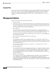
...Cable and Adapter Specifications" section on the switch. To launch the Device Manager, enter the switch IP address in your network through the console port and the supplied RJ-45-to view switch status and performance information. You can manage switches by using .... For more information. • Cisco IOS CLI. You can install and run it. you can use the CiscoView device-management application to run on your SNMP application. 1-24 Catalyst 2950 Switch Hardware Installation Guide OL-6156-01 Management Options Catalyst 2950 switches offer these management options: •...
...Cable and Adapter Specifications" section on the switch. To launch the Device Manager, enter the switch IP address in your network through the console port and the supplied RJ-45-to view switch status and performance information. You can manage switches by using .... For more information. • Cisco IOS CLI. You can install and run it. you can use the CiscoView device-management application to run on your SNMP application. 1-24 Catalyst 2950 Switch Hardware Installation Guide OL-6156-01 Management Options Catalyst 2950 switches offer these management options: •...

Hardware Installation Guide
Page 45
... information, see the switch software configuration guide and the documentation that works with your application. Chapter 1 Overview Management Options • Cisco Intelligence Engine 2100 (IE2100) The Cisco IE200 Series Configuration Registrar is a network management device that came with embedded Cisco Networking Services (CNS) agents in the switch software. OL-6156-01 Catalyst 2950 Switch Hardware Installation Guide 1-25...
... information, see the switch software configuration guide and the documentation that works with your application. Chapter 1 Overview Management Options • Cisco Intelligence Engine 2100 (IE2100) The Cisco IE200 Series Configuration Registrar is a network management device that came with embedded Cisco Networking Services (CNS) agents in the switch software. OL-6156-01 Catalyst 2950 Switch Hardware Installation Guide 1-25...

Hardware Installation Guide
Page 50
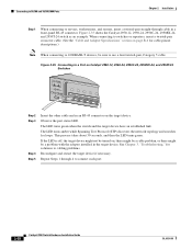
..., the cable length from the DC circuit. Be sure that power is removed from a switch to the chassis, ensure that no exposed portion of security. For specific cable lengths, see the CWDM GBIC module documentation. A restricted access area can conduct harmful ...procedures in the OFF position. Catalyst 2950 Switch Hardware Installation Guide 2-4 OL-6156-01 Statement 88 Installation Guidelines When determining where to place the switch, observe these guidelines. • Before installing the switch, first verify that services the DC circuit, switch the circuit breaker to be ...
..., the cable length from the DC circuit. Be sure that power is removed from a switch to the chassis, ensure that no exposed portion of security. For specific cable lengths, see the CWDM GBIC module documentation. A restricted access area can conduct harmful ...procedures in the OFF position. Catalyst 2950 Switch Hardware Installation Guide 2-4 OL-6156-01 Statement 88 Installation Guidelines When determining where to place the switch, observe these guidelines. • Before installing the switch, first verify that services the DC circuit, switch the circuit breaker to be ...

Hardware Installation Guide
Page 51
... Cisco representative or reseller for unrestricted cabling. - Verifying Package Contents Note Carefully remove the contents from a switch to the shipping container and save them. Two 19-inch or 24-inch rack-mounting brackets OL-6156-01 Catalyst 2950 Switch Hardware Installation Guide 2-5 The switch ... attached device cannot exceed 3 feet (1 meter). • For Long-Reach Ethernet (LRE) ports, cable-length specifications vary. Four rubber feet for the Catalyst 2950 Switch • AC power cord (not shipped with shielded cable grounded at both ends. See the "LRE Port" section...
... Cisco representative or reseller for unrestricted cabling. - Verifying Package Contents Note Carefully remove the contents from a switch to the shipping container and save them. Two 19-inch or 24-inch rack-mounting brackets OL-6156-01 Catalyst 2950 Switch Hardware Installation Guide 2-5 The switch ... attached device cannot exceed 3 feet (1 meter). • For Long-Reach Ethernet (LRE) ports, cable-length specifications vary. Four rubber feet for the Catalyst 2950 Switch • AC power cord (not shipped with shielded cable grounded at both ends. See the "LRE Port" section...
Hardware Installation Guide
Page 69
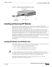
...specifications on installing, removing, and cabling the SFP module, refer to install and remove small-form-factor pluggable (SFP) modules. For detailed instructions on the other end of the potential damage to the cables, the cable connector, or the optical interfaces in a Switch Metal flap door 1 Catalyst 2950...way for Cisco to Table 1-2 for cable stipulations for the switch. Determine which type of the Catalyst 2950 LRE switches. SFP modules are inserted into SFP Module Slots SFP modules use any combination of SFP modules that the Catalyst 2950 LRE switch supports. Refer...
...specifications on installing, removing, and cabling the SFP module, refer to install and remove small-form-factor pluggable (SFP) modules. For detailed instructions on the other end of the potential damage to the cables, the cable connector, or the optical interfaces in a Switch Metal flap door 1 Catalyst 2950...way for Cisco to Table 1-2 for cable stipulations for the switch. Determine which type of the Catalyst 2950 LRE switches. SFP modules are inserted into SFP Module Slots SFP modules use any combination of SFP modules that the Catalyst 2950 LRE switch supports. Refer...
Hardware Installation Guide
Page 74
... repeaters, insert a twisted-pair crossover cable. (See the "Cable and Adapter Specifications" section on page B-6 for loops. The LED turns green when the switch and the target device have an established link. The LED turns amber while Spanning Tree Protocol (...-pair straight-through 4 to connect each port. 2-28 Catalyst 2950 Switch Hardware Installation Guide OL-6156-01 Observe the port status LED. See Chapter 3, "Troubleshooting," for solutions to a Port on Catalyst 2950-12, 2950-24, 2950C-24, 2950SX-24, and 2950T-24 Switches SYST RPS STAT UTIL DUPLX SPEED MODE 1x 2x 3x 4x...
... repeaters, insert a twisted-pair crossover cable. (See the "Cable and Adapter Specifications" section on page B-6 for loops. The LED turns green when the switch and the target device have an established link. The LED turns amber while Spanning Tree Protocol (...-pair straight-through 4 to connect each port. 2-28 Catalyst 2950 Switch Hardware Installation Guide OL-6156-01 Observe the port status LED. See Chapter 3, "Troubleshooting," for solutions to a Port on Catalyst 2950-12, 2950-24, 2950C-24, 2950SX-24, and 2950T-24 Switches SYST RPS STAT UTIL DUPLX SPEED MODE 1x 2x 3x 4x...
Hardware Installation Guide
Page 77
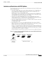
...Cisco LRE 48 POTS Splitter with a Catalyst 2950ST-24 LRE 997 Switch and a Cisco 576 LRE 997 CPE PC Cisco 576 LRE Cisco LRE 48 Catalyst 2950ST-24 997 CPE POTS splitter LRE 997 switch POTS Telephone Traffic from 0 to 120 kHz Traffic from a device attached to the CPE, such as shown in a specific... These limitations and restrictions apply when you use a POTS splitter with Catalyst 2950 LRE switches and Cisco LRE CPE devices: • The Catalyst 2950ST-8 LRE switch, Catalyst 2950ST-24 LRE switch, Cisco 575 LRE CPE, and Cisco 585 LRE CPE are designed to share lines with analog and ISDN ...
...Cisco LRE 48 POTS Splitter with a Catalyst 2950ST-24 LRE 997 Switch and a Cisco 576 LRE 997 CPE PC Cisco 576 LRE Cisco LRE 48 Catalyst 2950ST-24 997 CPE POTS splitter LRE 997 switch POTS Telephone Traffic from 0 to 120 kHz Traffic from a device attached to the CPE, such as shown in a specific... These limitations and restrictions apply when you use a POTS splitter with Catalyst 2950 LRE switches and Cisco LRE CPE devices: • The Catalyst 2950ST-8 LRE switch, Catalyst 2950ST-24 LRE switch, Cisco 575 LRE CPE, and Cisco 585 LRE CPE are designed to share lines with analog and ISDN ...

Hardware Installation Guide
Page 89
...vs. Reset the terminal-emulation software to display the switch boot loader. If the fan has failed, call Cisco Systems. • Use the show env fan privileged EXEC command. Incorrect baud rate. OL-6156-01 Catalyst 2950 Switch Hardware Installation Guide 3-3 Unreadable characters on page B-6....software. • Internal fan fault detected. • Nonfatal or fatal POST error detected. Refer to see the "Cable and Adapter Specifications" section on the management console. straight-through was required, or the reverse. • The cable is wired incorrectly. •...
...vs. Reset the terminal-emulation software to display the switch boot loader. If the fan has failed, call Cisco Systems. • Use the show env fan privileged EXEC command. Incorrect baud rate. OL-6156-01 Catalyst 2950 Switch Hardware Installation Guide 3-3 Unreadable characters on page B-6....software. • Internal fan fault detected. • Nonfatal or fatal POST error detected. Refer to see the "Cable and Adapter Specifications" section on the management console. straight-through was required, or the reverse. • The cable is wired incorrectly. •...

Hardware Installation Guide
Page 91
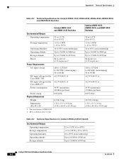
...Catalyst 2950 LRE switches. Table A-8 and Table A-9 list the regulatory agency approvals for the Catalyst 2950G-24-EI-DC switch. Table A-1 Technical Specifications for the switches other than the Catalyst 2950 Long-Reach Ethernet (LRE) switches. This switch meets ASTM D3332. 2. Table A-7 lists the regulatory agency approvals for Catalyst 2950-12, 2950-24, 2950C-24, 2950SX-24, and 2950T-24 Switches...input voltages for fiber-optic uplink ports. Table A-6 lists the technical specifications for the Cisco RPS 675 +12 V @4.5 A Power consumption 30 W (maximum) 102 Btus per ...
...Catalyst 2950 LRE switches. Table A-8 and Table A-9 list the regulatory agency approvals for the Catalyst 2950G-24-EI-DC switch. Table A-1 Technical Specifications for the switches other than the Catalyst 2950 Long-Reach Ethernet (LRE) switches. This switch meets ASTM D3332. 2. Table A-7 lists the regulatory agency approvals for Catalyst 2950-12, 2950-24, 2950C-24, 2950SX-24, and 2950T-24 Switches...input voltages for fiber-optic uplink ports. Table A-6 lists the technical specifications for the Cisco RPS 675 +12 V @4.5 A Power consumption 30 W (maximum) 102 Btus per ...
Hardware Installation Guide
Page 92
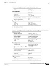
... Specifications Table A-2 Technical Specifications for Catalyst 2950G-12-EI, 2950G-24-EI, 2950G-48-EI, 2950SX-48-SI, and 2950T-48-SI Switches Catalyst 2950G-12-EI and 2950G-24-EI Switches Environmental...DC input voltage for the +12 V @4.5 A Cisco RPS2 300 DC input voltage for Catalyst 2950G-24-EI-DC Switch Environmental Ranges Operating temperature Storage temperature Operating humidity Operating...m) Catalyst 2950 Switch Hardware Installation Guide A-2 OL-6156-01 This switch meets ASTM D3332. 2. RPS = redundant power system Catalyst 2950G-48-EI, 2950SX-48-SI, and 2950T-48-SI Switches 32...
... Specifications Table A-2 Technical Specifications for Catalyst 2950G-12-EI, 2950G-24-EI, 2950G-48-EI, 2950SX-48-SI, and 2950T-48-SI Switches Catalyst 2950G-12-EI and 2950G-24-EI Switches Environmental...DC input voltage for the +12 V @4.5 A Cisco RPS2 300 DC input voltage for Catalyst 2950G-24-EI-DC Switch Environmental Ranges Operating temperature Storage temperature Operating humidity Operating...m) Catalyst 2950 Switch Hardware Installation Guide A-2 OL-6156-01 This switch meets ASTM D3332. 2. RPS = redundant power system Catalyst 2950G-48-EI, 2950SX-48-SI, and 2950T-48-SI Switches 32...
Hardware Installation Guide
Page 93
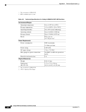
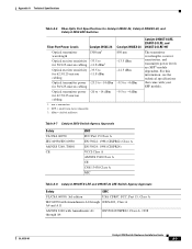
... D) 1.73 x 17.5 x 9.96 in. (4.36 x 44.45 x 24.18 cm) Catalyst 2950 Switch Hardware Installation Guide A-3 per sec (2.13 m per sec)1 Power Requirements AC input voltage DC input voltage for the Cisco RPS2 300 100 to 127/200 to 240 VAC (autoranging) 50 to 60 Hz ... W x D) 1. Appendix A Technical Specifications OL-6156-01 Table A-3 Technical Specifications for Catalyst 2950G-24-EI-DC Switch Shock Power Requirements Power consumption Power rating DC input voltage Wire gauge for Catalyst 2950ST-8 LRE and Catalyst-2950ST-24 LRE Switches Environmental Ranges Operating temperature 32 to 113...
... D) 1.73 x 17.5 x 9.96 in. (4.36 x 44.45 x 24.18 cm) Catalyst 2950 Switch Hardware Installation Guide A-3 per sec (2.13 m per sec)1 Power Requirements AC input voltage DC input voltage for the Cisco RPS2 300 100 to 127/200 to 240 VAC (autoranging) 50 to 60 Hz ... W x D) 1. Appendix A Technical Specifications OL-6156-01 Table A-3 Technical Specifications for Catalyst 2950G-24-EI-DC Switch Shock Power Requirements Power consumption Power rating DC input voltage Wire gauge for Catalyst 2950ST-8 LRE and Catalyst-2950ST-24 LRE Switches Environmental Ranges Operating temperature 32 to 113...
Hardware Installation Guide
Page 94
... Technical Specifications for Catalyst-2950ST-24 997 LRE Switches Environmental Ranges Operating temperature Storage temperature Operating humidity Operating altitude Storage altitude Shock Power Requirements Power consumption Power rating DC input voltage Wire gauge for protective earth) 5 A 8 lb (3.6 kg) 1.73 x 17.5 x 9.96 in . This switch meets ...(maximum) 171 Btus per hour 0.083 kVA -36 to 15,000 ft (4570 m) 84 in . (4.36 x 44.45 x 24.18 cm) Catalyst 2950 Switch Hardware Installation Guide A-4 OL-6156-01 AWG = American Wire Gauge 32 to 113°F (0 to 45°C) -13 to 158°...
... Technical Specifications for Catalyst-2950ST-24 997 LRE Switches Environmental Ranges Operating temperature Storage temperature Operating humidity Operating altitude Storage altitude Shock Power Requirements Power consumption Power rating DC input voltage Wire gauge for protective earth) 5 A 8 lb (3.6 kg) 1.73 x 17.5 x 9.96 in . This switch meets ...(maximum) 171 Btus per hour 0.083 kVA -36 to 15,000 ft (4570 m) 84 in . (4.36 x 44.45 x 24.18 cm) Catalyst 2950 Switch Hardware Installation Guide A-4 OL-6156-01 AWG = American Wire Gauge 32 to 113°F (0 to 45°C) -13 to 158°...
Hardware Installation Guide
Page 95
... and A11 AS/NZS 3260 with your SFP module. nm = nanometers 2. SFP = small form-factor pluggable 3. Appendix A Technical Specifications Table A-6 Fiber-Optic Port Specifications for Catalyst 2950C-24, Catalyst 2950SX-24, and Catalyst 2950 LRE Switches Fiber-Port Power Levels Catalyst 2950C-24 Optical transmitter wavelength 1300 nm1 Optical receiver sensitivity -33.5 to for 50/125-micron cabling -11.8 dBm3 Optical...
... and A11 AS/NZS 3260 with your SFP module. nm = nanometers 2. SFP = small form-factor pluggable 3. Appendix A Technical Specifications Table A-6 Fiber-Optic Port Specifications for Catalyst 2950C-24, Catalyst 2950SX-24, and Catalyst 2950 LRE Switches Fiber-Port Power Levels Catalyst 2950C-24 Optical transmitter wavelength 1300 nm1 Optical receiver sensitivity -33.5 to for 50/125-micron cabling -11.8 dBm3 Optical...

Hardware Installation Guide
Page 96
Appendix A Technical Specifications Table A-8 Catalyst 2950ST-8 LRE and 2950ST-24 LRE Switch Agency Approvals (continued) Safety EMC TUV-GS to EN60950 with Amendments EN 55024:..., and Short Voltage Interruptions AS/NZS 3548, Class A BSMI, Class A VCCI, Class A MIC Mark Table A-9 Catalyst 2950ST-24 LRE 997 Switch Agency Approvals Safety EMC UL/CSA 60950, 3rd edition USA CFR47, FCC, Part 15, Class A IEC 60950 with Amendments...11/IEC1000-4-11: Immunity to Voltage Dips, Voltage Variations, and Short Voltage Interruptions Catalyst 2950 Switch Hardware Installation Guide A-6 OL-6156-01
Appendix A Technical Specifications Table A-8 Catalyst 2950ST-8 LRE and 2950ST-24 LRE Switch Agency Approvals (continued) Safety EMC TUV-GS to EN60950 with Amendments EN 55024:..., and Short Voltage Interruptions AS/NZS 3548, Class A BSMI, Class A VCCI, Class A MIC Mark Table A-9 Catalyst 2950ST-24 LRE 997 Switch Agency Approvals Safety EMC UL/CSA 60950, 3rd edition USA CFR47, FCC, Part 15, Class A IEC 60950 with Amendments...11/IEC1000-4-11: Immunity to Voltage Dips, Voltage Variations, and Short Voltage Interruptions Catalyst 2950 Switch Hardware Installation Guide A-6 OL-6156-01