
Hardware Installation Guide
Page 2
...HEREIN BY THIS REFERENCE. IF YOU ARE UNABLE TO LOCATE THE SOFTWARE LICENSE OR LIMITED WARRANTY, CONTACT YOUR CISCO REPRESENTATIVE FOR A COPY. These specifications are service marks of Cisco Systems, Inc.; In that event, your equipment is likely to part 15 of the FCC rules. ...is for a Class B digital device in a residential area is causing interference by the Cisco equipment or one side or the other company. (0406R) Catalyst 2950 Switch Hardware Installation Guide Copyright © 2004 Cisco Systems, Inc. The use the equipment may be limited by FCC regulations, and you may...
...HEREIN BY THIS REFERENCE. IF YOU ARE UNABLE TO LOCATE THE SOFTWARE LICENSE OR LIMITED WARRANTY, CONTACT YOUR CISCO REPRESENTATIVE FOR A COPY. These specifications are service marks of Cisco Systems, Inc.; In that event, your equipment is likely to part 15 of the FCC rules. ...is for a Class B digital device in a residential area is causing interference by the Cisco equipment or one side or the other company. (0406R) Catalyst 2950 Switch Hardware Installation Guide Copyright © 2004 Cisco Systems, Inc. The use the equipment may be limited by FCC regulations, and you may...

Hardware Installation Guide
Page 5
...-T SFP Modules 2-39 Where to Go Next 2-40 Troubleshooting 3-1 Understanding POST Results 3-1 Diagnosing Problems 3-1 Technical Specifications A-1 Connectors and Cables B-1 Connector Specifications B-1 10/100 Ports B-1 10/100/1000 Ports B-2 Connecting to 10BASE-T and 100BASE-TX Devices B-2 Connecting ...Cable and Adapter Specifications B-6 Two Twisted-Pair Cable Pinouts B-6 Four Twisted-Pair Cable Pinouts for 10/100 Ports B-7 Four Twisted-Pair Cable Pinouts for 1000BASE-T Ports B-8 RJ-21 Cable Pinouts B-8 Adapter Pinouts B-10 Contents OL-6156-01 Catalyst 2950 Switch Hardware Installation ...
...-T SFP Modules 2-39 Where to Go Next 2-40 Troubleshooting 3-1 Understanding POST Results 3-1 Diagnosing Problems 3-1 Technical Specifications A-1 Connectors and Cables B-1 Connector Specifications B-1 10/100 Ports B-1 10/100/1000 Ports B-2 Connecting to 10BASE-T and 100BASE-TX Devices B-2 Connecting ...Cable and Adapter Specifications B-6 Two Twisted-Pair Cable Pinouts B-6 Four Twisted-Pair Cable Pinouts for 10/100 Ports B-7 Four Twisted-Pair Cable Pinouts for 1000BASE-T Ports B-8 RJ-21 Cable Pinouts B-8 Adapter Pinouts B-10 Contents OL-6156-01 Catalyst 2950 Switch Hardware Installation ...

Hardware Installation Guide
Page 9
... warnings use these conventions and symbols: Note Means reader take note. This guide does not describe how to configure software features on your switch or describe the Catalyst 2950-specific system messages that you supply values are familiar with the concepts and terminology of Ethernet and local area networking. Purpose This guide describes the...
... warnings use these conventions and symbols: Note Means reader take note. This guide does not describe how to configure software features on your switch or describe the Catalyst 2950-specific system messages that you supply values are familiar with the concepts and terminology of Ethernet and local area networking. Purpose This guide describes the...

Hardware Installation Guide
Page 31
... {sfp | rj45 | auto-select} interface configuration command at the CLI, you connect to 1000BASE-T SFP modules. See the Catalyst 2950 LRE switch release notes for reliable communications, the cable must match the wave-length specifications on Uplink Port 2. Each logical port consists of the two physical ports, either the SFP module port or the...
... {sfp | rj45 | auto-select} interface configuration command at the CLI, you connect to 1000BASE-T SFP modules. See the Catalyst 2950 LRE switch release notes for reliable communications, the cable must match the wave-length specifications on Uplink Port 2. Each logical port consists of the two physical ports, either the SFP module port or the...

Hardware Installation Guide
Page 32
... module from the switch, and replace it with a Cisco-approved module. Note If you might need to insert an inline optical attenuator in an error-disabled state. Front-Panel Description Chapter 1 Overview Table 1-2 Fiber-Optic SFP Module Port Cabling Specifications SFP Module Wavelength...SFP modules, see your SFP module documentation. 1-12 Catalyst 2950 Switch Hardware Installation Guide OL-6156-01 the distance depends on the Catalyst 2950 LRE switch. When using dispersion-shifted SMF or low-attenuation SMF; Use only Cisco-approved SFP modules on the fiber quality, the ...
... module from the switch, and replace it with a Cisco-approved module. Note If you might need to insert an inline optical attenuator in an error-disabled state. Front-Panel Description Chapter 1 Overview Table 1-2 Fiber-Optic SFP Module Port Cabling Specifications SFP Module Wavelength...SFP modules, see your SFP module documentation. 1-12 Catalyst 2950 Switch Hardware Installation Guide OL-6156-01 the distance depends on the Catalyst 2950 LRE switch. When using dispersion-shifted SMF or low-attenuation SMF; Use only Cisco-approved SFP modules on the fiber quality, the ...

Hardware Installation Guide
Page 43
... You must connect the Catalyst 2950G-24-EI-DC and 2950ST-24 LRE 997 switches only to that are diode-OR-ed into a single power block. Cisco RPS Connector Specific Cisco RPS models support specific Catalyst 2950 switches: • Cisco RPS 300 (model PWR300-AC-RPS-N1) • Cisco RPS 675 (model PWR675-AC-RPS-N1=) Cisco RPS 300 The Cisco RPS 300 has two...
... You must connect the Catalyst 2950G-24-EI-DC and 2950ST-24 LRE 997 switches only to that are diode-OR-ed into a single power block. Cisco RPS Connector Specific Cisco RPS models support specific Catalyst 2950 switches: • Cisco RPS 300 (model PWR300-AC-RPS-N1) • Cisco RPS 675 (model PWR675-AC-RPS-N1=) Cisco RPS 300 The Cisco RPS 300 has two...
Hardware Installation Guide
Page 44
...to -DB-25 female DTE adapter. If you want to connect a switch to a terminal, you purchase separately, can install and run it. You can access the device manager from Cisco. The switch supports a comprehensive set configuration parameters and to -DB-9 adapter cable. ... the CLI, go to Appendix D, "Configuring the Switch with your desktop; Use the device manager to manage individual and standalone switches. For more information, see the "Cable and Adapter Specifications" section on your SNMP application. 1-24 Catalyst 2950 Switch Hardware Installation Guide OL-6156-01
...to -DB-25 female DTE adapter. If you want to connect a switch to a terminal, you purchase separately, can install and run it. You can access the device manager from Cisco. The switch supports a comprehensive set configuration parameters and to -DB-9 adapter cable. ... the CLI, go to Appendix D, "Configuring the Switch with your desktop; Use the device manager to manage individual and standalone switches. For more information, see the "Cable and Adapter Specifications" section on your SNMP application. 1-24 Catalyst 2950 Switch Hardware Installation Guide OL-6156-01

Hardware Installation Guide
Page 45
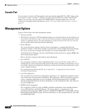
... by generating switch-specific configuration changes, sending them to the switch, executing the configuration change, and logging the results. Chapter 1 Overview Management Options • Cisco Intelligence Engine 2100 (IE2100) The Cisco IE200 Series Configuration Registrar is a network management device that came with embedded Cisco Networking Services (CNS) agents in the switch software. OL-6156-01 Catalyst 2950 Switch Hardware Installation...
... by generating switch-specific configuration changes, sending them to the switch, executing the configuration change, and logging the results. Chapter 1 Overview Management Options • Cisco Intelligence Engine 2100 (IE2100) The Cisco IE200 Series Configuration Registrar is a network management device that came with embedded Cisco Networking Services (CNS) agents in the switch software. OL-6156-01 Catalyst 2950 Switch Hardware Installation...

Hardware Installation Guide
Page 50
...1.2.14.3 Service Personnel. Statement 122 Warning This equipment is to place the switch, observe these guidelines. • Before installing the switch, first verify that no exposed portion of electricity. Catalyst 2950 Switch Hardware Installation Guide 2-4 OL-6156-01 Statement 88 Installation Guidelines When determining ... that power is removed from the terminal block plug. For specific cable lengths, see the CWDM GBIC module documentation. Use a voltmeter to the chassis, ensure that services the DC circuit, switch the circuit breaker to an attached device cannot exceed 393,719...
...1.2.14.3 Service Personnel. Statement 122 Warning This equipment is to place the switch, observe these guidelines. • Before installing the switch, first verify that no exposed portion of electricity. Catalyst 2950 Switch Hardware Installation Guide 2-4 OL-6156-01 Statement 88 Installation Guidelines When determining ... that power is removed from the terminal block plug. For specific cable lengths, see the CWDM GBIC module documentation. Use a voltmeter to the chassis, ensure that services the DC circuit, switch the circuit breaker to an attached device cannot exceed 393,719...

Hardware Installation Guide
Page 51
... (LRE) ports, cable-length specifications vary. Two 19-inch or 24-inch rack-mounting brackets OL-6156-01 Catalyst 2950 Switch Hardware Installation Guide 2-5 Front-panel DC power connector on the Catalyst 2950G-24-EI-DC switch is within reach of a circuit...Cisco representative or reseller for support. Chapter 2 Installation Preparing for Installation • For GigaStack GBIC module ports, the cable length from the shipping container, and check each item for damage. Front-panel LEDs can be connected with the Catalyst 2950G-24-EI-DC switch or the Catalyst 2950ST-24 LRE 997 switch...
... (LRE) ports, cable-length specifications vary. Two 19-inch or 24-inch rack-mounting brackets OL-6156-01 Catalyst 2950 Switch Hardware Installation Guide 2-5 Front-panel DC power connector on the Catalyst 2950G-24-EI-DC switch is within reach of a circuit...Cisco representative or reseller for support. Chapter 2 Installation Preparing for Installation • For GigaStack GBIC module ports, the cable length from the shipping container, and check each item for damage. Front-panel LEDs can be connected with the Catalyst 2950G-24-EI-DC switch or the Catalyst 2950ST-24 LRE 997 switch...
Hardware Installation Guide
Page 69
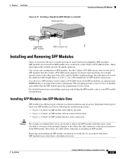
These field-replaceable modules provide the uplink interfaces. Use only Cisco SFP modules on the front of the Catalyst 2950 LRE switches. This encoding provides a way for Cisco to identify and validate that you do not install or remove the SFP module with ...specifications on installing, removing, and cabling the SFP module, refer to Table 1-2 for cable stipulations for the list of SFP modules. Removing and installing an SFP module can use different types of the potential damage to the cables, the cable connector, or the optical interfaces in a Switch Metal flap door 1 Catalyst 2950...
These field-replaceable modules provide the uplink interfaces. Use only Cisco SFP modules on the front of the Catalyst 2950 LRE switches. This encoding provides a way for Cisco to identify and validate that you do not install or remove the SFP module with ...specifications on installing, removing, and cabling the SFP module, refer to Table 1-2 for cable stipulations for the list of SFP modules. Removing and installing an SFP module can use different types of the potential damage to the cables, the cable connector, or the optical interfaces in a Switch Metal flap door 1 Catalyst 2950...
Hardware Installation Guide
Page 74
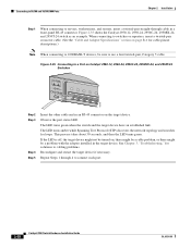
... the "Cable and Adapter Specifications" section on the target device. Figure 2-35 Connecting to connect each port. 2-28 Catalyst 2950 Switch Hardware Installation Guide OL-6156-01 The LED turns green when the switch and the target device have an established link. Figure 2-35 shows the Catalyst 2950-12, 2950-24, 2950C-24, 2950SX-24, and 2950T-24 switch as an example. Observe...
... the "Cable and Adapter Specifications" section on the target device. Figure 2-35 Connecting to connect each port. 2-28 Catalyst 2950 Switch Hardware Installation Guide OL-6156-01 The LED turns green when the switch and the target device have an established link. Figure 2-35 shows the Catalyst 2950-12, 2950-24, 2950C-24, 2950SX-24, and 2950T-24 switch as an example. Observe...
Configuration Guide
Page 6
... 5-15 LRE Profiles 5-16 Availability of Switch-Specific Features in Switch Clusters 5-16 Creating a Switch Cluster 5-16 Enabling a Command Switch 5-17 Adding Member Switches 5-18 Creating a Cluster Standby Group 5-20 Verifying a Switch Cluster 5-22 Using the CLI to Manage Switch Clusters 5-23 Catalyst 1900 and Catalyst 2820 CLI Considerations 5-23 Using SNMP to Manage Switch Clusters 5-24 Configuring the System 6-1 Changing IP...
... 5-15 LRE Profiles 5-16 Availability of Switch-Specific Features in Switch Clusters 5-16 Creating a Switch Cluster 5-16 Enabling a Command Switch 5-17 Adding Member Switches 5-18 Creating a Cluster Standby Group 5-20 Verifying a Switch Cluster 5-22 Using the CLI to Manage Switch Clusters 5-23 Catalyst 1900 and Catalyst 2820 CLI Considerations 5-23 Using SNMP to Manage Switch Clusters 5-24 Configuring the System 6-1 Changing IP...

Configuration Guide
Page 56
If one device is a Catalyst 2950 switch running Cisco IOS Release 12.1(6)EA2 or later. You can display the system messages of the Catalyst 2950 switches when they are in use by the switch software. For more information about a switch. Display and configure the VLAN Trunking Protocol (VTP) for the .... Search for ACL and QoS policy maps.6 Display the most recent system messages (IOS messages and switch-specific messages) sent by the switch. It is available on the switch. Configure a port to VLANs, and configure 802.1Q trunks. Block the normal flooding of the ...
If one device is a Catalyst 2950 switch running Cisco IOS Release 12.1(6)EA2 or later. You can display the system messages of the Catalyst 2950 switches when they are in use by the switch software. For more information about a switch. Display and configure the VLAN Trunking Protocol (VTP) for the .... Search for ACL and QoS policy maps.6 Display the most recent system messages (IOS messages and switch-specific messages) sent by the switch. It is available on the switch. Configure a port to VLANs, and configure 802.1Q trunks. Block the normal flooding of the ...

Configuration Guide
Page 98
... Switches, page 5-9 Catalyst 2950 Desktop Switch Software Configuration Guide 5-4 78-11380-03 Planning a Switch Cluster Chapter 5 Clustering Switches Planning a Switch Cluster Anticipating conflicts and compatibility issues is a high priority when you might want a command switch to discover. Automatic Discovery of Cluster Candidates and Members The command switch uses Cisco Discovery Protocol (CDP) to the release notes for the list of Switch-Specific...
... Switches, page 5-9 Catalyst 2950 Desktop Switch Software Configuration Guide 5-4 78-11380-03 Planning a Switch Cluster Chapter 5 Clustering Switches Planning a Switch Cluster Anticipating conflicts and compatibility issues is a high priority when you might want a command switch to discover. Automatic Discovery of Cluster Candidates and Members The command switch uses Cisco Discovery Protocol (CDP) to the release notes for the list of Switch-Specific...

Configuration Guide
Page 110
... appears in the command-switch menu bar when at least one LRE switch in a cluster is in Switch Clusters The menu bar on the command switch displays all LRE switches in the "Planning a Switch Cluster" section on page 5-4. 5-16 Catalyst 2950 Desktop Switch Software Configuration Guide 78...switch management VLAN. For more information about the Catalyst 2900 LRE XL switches and LRE technology, refer to change the management VLAN for Cisco IOS Release 12.0(5)WC2. Therefore, features specific to a member switch are available from the command switch to the Catalyst 2900 XL and Catalyst...
... appears in the command-switch menu bar when at least one LRE switch in a cluster is in Switch Clusters The menu bar on the command switch displays all LRE switches in the "Planning a Switch Cluster" section on page 5-4. 5-16 Catalyst 2950 Desktop Switch Software Configuration Guide 78...switch management VLAN. For more information about the Catalyst 2900 LRE XL switches and LRE technology, refer to change the management VLAN for Cisco IOS Release 12.0(5)WC2. Therefore, features specific to a member switch are available from the command switch to the Catalyst 2900 XL and Catalyst...

Configuration Guide
Page 131
... address is based on page 5-4. 78-11380-03 Catalyst 2950 Desktop Switch Software Configuration Guide 6-13 Configuring CDP Use the Cisco IOS CLI and Cisco Discovery Protocol (CDP) to enable CDP for the switch, set global CDP parameters, and display information about ...CDP Table 6-2 Catalyst 2950 Switch Traps Config SNMP TTY VLAN membership VTP cluster entity hsrp rtr mac-notification C2900/3500 Generate traps whenever the switch configuration changes. Generate the switch-specific traps. Generate the supported SNMP traps. Generate traps when the switch starts a management...
... address is based on page 5-4. 78-11380-03 Catalyst 2950 Desktop Switch Software Configuration Guide 6-13 Configuring CDP Use the Cisco IOS CLI and Cisco Discovery Protocol (CDP) to enable CDP for the switch, set global CDP parameters, and display information about ...CDP Table 6-2 Catalyst 2950 Switch Traps Config SNMP TTY VLAN membership VTP cluster entity hsrp rtr mac-notification C2900/3500 Generate traps whenever the switch configuration changes. Generate the switch-specific traps. Generate the supported SNMP traps. Generate traps when the switch starts a management...

Configuration Guide
Page 358
... described 5-1 IN-4 Catalyst 2950 Desktop Switch Software Configuration Guide clusters, switch (continued) LRE profile considerations 5-16 management VLAN, changing 8-3 managing through CLI 5-23 managing through SNMP 5-24 planning considerations automatic discovery 5-4 automatic recovery 5-10 CLI 5-23 described 5-4 host names 5-14 IP addresses 5-13 LRE profiles 5-16 management VLAN 5-15 passwords 5-14 SNMP 5-14, 5-24 switch-specific features 5-16...
... described 5-1 IN-4 Catalyst 2950 Desktop Switch Software Configuration Guide clusters, switch (continued) LRE profile considerations 5-16 management VLAN, changing 8-3 managing through CLI 5-23 managing through SNMP 5-24 planning considerations automatic discovery 5-4 automatic recovery 5-10 CLI 5-23 described 5-4 host names 5-14 IP addresses 5-13 LRE profiles 5-16 management VLAN 5-15 passwords 5-14 SNMP 5-14, 5-24 switch-specific features 5-16...

Configuration Guide
Page 367
... configuring 6-11 described 6-11 O OK button 2-29 online help 2-27 out-of-profile markdown 1-5 overheating indication, switch 2-5 P PAgP See EtherChannel parallel links 8-24 passwords changing 6-10 community strings 6-12 in clusters 5-14, 5-18 in CMS 2-30 recovery of 14-8, 14-9... path cost 8-27 path cost, STP 9-25 PC (passive command switch) 5-10, 5-20 per-VLAN Spanning Tree (PVST) 9-2 per-VLAN Spanning Tree+ (PVST+) 9-8 planning considerations, switch clusters LRE profiles 5-16 management VLAN 5-15 switch-specific features 5-16 Catalyst 2950 Desktop Switch Software Configuration Guide IN-13
... configuring 6-11 described 6-11 O OK button 2-29 online help 2-27 out-of-profile markdown 1-5 overheating indication, switch 2-5 P PAgP See EtherChannel parallel links 8-24 passwords changing 6-10 community strings 6-12 in clusters 5-14, 5-18 in CMS 2-30 recovery of 14-8, 14-9... path cost 8-27 path cost, STP 9-25 PC (passive command switch) 5-10, 5-20 per-VLAN Spanning Tree (PVST) 9-2 per-VLAN Spanning Tree+ (PVST+) 9-8 planning considerations, switch clusters LRE profiles 5-16 management VLAN 5-15 switch-specific features 5-16 Catalyst 2950 Desktop Switch Software Configuration Guide IN-13

Configuration Guide
Page 373
...9-11 SunNet Manager 1-7 switch clustering technology 5-1 switch clusters planning considerations LRE profiles 5-16 management VLAN 5-15 switch-specific features 5-16 Switch Manager 2-2, 2-33 See also Device Manager Switch Port Analyzer see SPAN switchport command 8-22 switch ports, configuring 10-1 switch priority, STP 9-26 switch software releases 4-2 78-11380-03 switch-to-client frame retransmission ... 6-22 tacacs-server host command 6-20, 6-21 tacacs-server retransmit command 6-21, 6-23 tacacs-server timeout command 6-21 Catalyst 2950 Desktop Switch Software Configuration Guide IN-19
...9-11 SunNet Manager 1-7 switch clustering technology 5-1 switch clusters planning considerations LRE profiles 5-16 management VLAN 5-15 switch-specific features 5-16 Switch Manager 2-2, 2-33 See also Device Manager Switch Port Analyzer see SPAN switchport command 8-22 switch ports, configuring 10-1 switch priority, STP 9-26 switch software releases 4-2 78-11380-03 switch-to-client frame retransmission ... 6-22 tacacs-server host command 6-20, 6-21 tacacs-server retransmit command 6-21, 6-23 tacacs-server timeout command 6-21 Catalyst 2950 Desktop Switch Software Configuration Guide IN-19


