
Hardware Installation Guide
Page 4
... SFP Module Slots 2-25 Connecting to 10/100 and 10/100/1000 Ports 2-27 Connecting to 100BASE-FX and 1000BASE-SX Ports 2-29 Connecting to an LRE Port 2-30 Connection Guidelines 2-30 Limitations and Restrictions with POTS Splitters 2-31 Required Cables 2-32 Connecting to a Patch Panel or POTS Splitter 2-32 Catalyst 2950 Switch Hardware Installation Guide iv OL-6156-01
... SFP Module Slots 2-25 Connecting to 10/100 and 10/100/1000 Ports 2-27 Connecting to 100BASE-FX and 1000BASE-SX Ports 2-29 Connecting to an LRE Port 2-30 Connection Guidelines 2-30 Limitations and Restrictions with POTS Splitters 2-31 Required Cables 2-32 Connecting to a Patch Panel or POTS Splitter 2-32 Catalyst 2950 Switch Hardware Installation Guide iv OL-6156-01
Hardware Installation Guide
Page 21
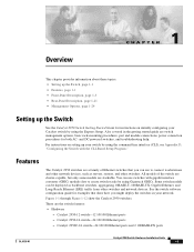
... using the Express Setup. Catalyst 2950-12 switch-12 10/100 Ethernet ports - Features The Catalyst 2950 switches are switch management options, basic rack-mounting procedures, port and module connections, power connection procedures for both AC- Some switch models can use switches with the CLI-Based Setup Program." These are stackable. Catalyst 2950C-24 switch-24 10/100 Ethernet ports and 2 100BASE-FX ports OL-6156-01 Catalyst 2950 Switch Hardware Installation Guide 1-1 All...
... using the Express Setup. Catalyst 2950-12 switch-12 10/100 Ethernet ports - Features The Catalyst 2950 switches are switch management options, basic rack-mounting procedures, port and module connections, power connection procedures for both AC- Some switch models can use switches with the CLI-Based Setup Program." These are stackable. Catalyst 2950C-24 switch-24 10/100 Ethernet ports and 2 100BASE-FX ports OL-6156-01 Catalyst 2950 Switch Hardware Installation Guide 1-1 All...

Hardware Installation Guide
Page 22
... one time.) - Catalyst 2950T-24 switch-24 10/100 Ethernet ports and 2 10/100/1000 Ethernet ports - Catalyst 2950T-48-SI switch-48 10/100 Ethernet ports and 2 10/100/1000 Ethernet ports - On Catalyst 2950G-12-EI, 2950G-24-EI, 2950G-24-EI-DC, and 2950G-48-EI switches, support for the Catalyst 2950 LRE switches. - For 100BASE-FX ports, supports only 100-Mbps and full-duplex settings - Catalyst 2950ST-24 LRE 997 switch-24 LRE ports, 2 10/100/1000 Ethernet ports, and 2 SFP...
... one time.) - Catalyst 2950T-24 switch-24 10/100 Ethernet ports and 2 10/100/1000 Ethernet ports - Catalyst 2950T-48-SI switch-48 10/100 Ethernet ports and 2 10/100/1000 Ethernet ports - On Catalyst 2950G-12-EI, 2950G-24-EI, 2950G-24-EI-DC, and 2950G-48-EI switches, support for the Catalyst 2950 LRE switches. - For 100BASE-FX ports, supports only 100-Mbps and full-duplex settings - Catalyst 2950ST-24 LRE 997 switch-24 LRE ports, 2 10/100/1000 Ethernet ports, and 2 SFP...
Hardware Installation Guide
Page 25
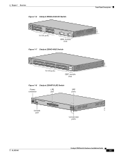
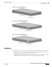
... RPS STAT UTIL DUPLX SPEED MODE 1 1X 23 45 67 8 9 10 11 12 11X 2X 12X 13X 13 14 15 16 17 18 19 20 21 22 23 24 23X 14X 24X 10/100 ports 1 Catalyst 2950 SERIES 2 GBIC module slots Figure 1-7 Catalyst 2950G-48-EI Switch SYST RPS STAT UTIL DUPLX SPEED MODE 1 1X 2X 23 45 67... 8 9 10 11 12 13 14 15 16 17 15X 17X 18 19 20 21...
... RPS STAT UTIL DUPLX SPEED MODE 1 1X 23 45 67 8 9 10 11 12 11X 2X 12X 13X 13 14 15 16 17 18 19 20 21 22 23 24 23X 14X 24X 10/100 ports 1 Catalyst 2950 SERIES 2 GBIC module slots Figure 1-7 Catalyst 2950G-48-EI Switch SYST RPS STAT UTIL DUPLX SPEED MODE 1 1X 2X 23 45 67... 8 9 10 11 12 13 14 15 16 17 15X 17X 18 19 20 21...
Hardware Installation Guide
Page 26
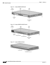
... Front-Panel Description Figure 1-9 Catalyst 2950ST-24 LRE Switch Power LRE connector port SFP ports 110.00A-1/02R.75A/TA2I0N500G--26400HVZ~ MODE SYST RPS STAT SPEED CONSOLE 1 2 3 4 5 6 7 8 9 10 11 12 Console port 13 14 15 16 17 18 19 20 21 22 23 24 Catalyst 2950 SERIES LRE 1 2 1 2 10/100/1000 ports Figure 1-10 Catalyst 2950ST-24 LRE 997 Switch Power connector LRE port SFP ports - ++ A INPCUUTR:RE3N6T- B 72...
... Front-Panel Description Figure 1-9 Catalyst 2950ST-24 LRE Switch Power LRE connector port SFP ports 110.00A-1/02R.75A/TA2I0N500G--26400HVZ~ MODE SYST RPS STAT SPEED CONSOLE 1 2 3 4 5 6 7 8 9 10 11 12 Console port 13 14 15 16 17 18 19 20 21 22 23 24 Catalyst 2950 SERIES LRE 1 2 1 2 10/100/1000 ports Figure 1-10 Catalyst 2950ST-24 LRE 997 Switch Power connector LRE port SFP ports - ++ A INPCUUTR:RE3N6T- B 72...
Hardware Installation Guide
Page 27
...Catalyst 2950T-24 Switch Front-Panel Description 47337 SYST RPS STAT UTIL DUPLX SPEED MODE 1x 2x 3x 4x 5x 6x 7x 8x 9x 10x 11x 10Base-T / 100Base-TX 12x 13x 14x 15x 16x 17x 18x 19x 20x 21x 22x 23x Catalyst 2950 SERIES 24x 10/100/100Base-T 1 2 10/100 ports 10/100/1000 ports Figure 1-13 Catalyst 2950SX-48-SI Switch ... 21 22 23 24 25 26 27 28 29 30 31 32 16X 18X 33 31X 33X 34 35 36 37 38 39 40 41 42 43 44 45 46 47 48 47X 32X 34X 48X 10/100 ports Catalyst 2950 SERIES 1 2 1000BASE-SX ports Figure 1-14 Catalyst 2950T-48-SI Switch 97626 SYST RPS...
...Catalyst 2950T-24 Switch Front-Panel Description 47337 SYST RPS STAT UTIL DUPLX SPEED MODE 1x 2x 3x 4x 5x 6x 7x 8x 9x 10x 11x 10Base-T / 100Base-TX 12x 13x 14x 15x 16x 17x 18x 19x 20x 21x 22x 23x Catalyst 2950 SERIES 24x 10/100/100Base-T 1 2 10/100 ports 10/100/1000 ports Figure 1-13 Catalyst 2950SX-48-SI Switch ... 21 22 23 24 25 26 27 28 29 30 31 32 16X 18X 33 31X 33X 34 35 36 37 38 39 40 41 42 43 44 45 46 47 48 47X 32X 34X 48X 10/100 ports Catalyst 2950 SERIES 1 2 1000BASE-SX ports Figure 1-14 Catalyst 2950T-48-SI Switch 97626 SYST RPS...
Hardware Installation Guide
Page 28
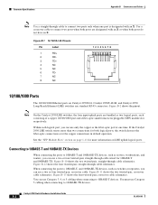
... a 1000BASE-T device, be explicitly set to operate at 1000 Mbps in Appendix B, "Connectors and Cables." The 10/100/1000 ports on Catalyst 2950T-24, Catalyst 2950T-48-SI, and Catalyst 2950 LRE switches use RJ-45 connectors and twisted-pair cabling. The 10/100/1000 ports can connect to these devices: • 10BASE-T devices, such as workstations and hubs, through standard RJ...
... a 1000BASE-T device, be explicitly set to operate at 1000 Mbps in Appendix B, "Connectors and Cables." The 10/100/1000 ports on Catalyst 2950T-24, Catalyst 2950T-48-SI, and Catalyst 2950 LRE switches use RJ-45 connectors and twisted-pair cabling. The 10/100/1000 ports can connect to these devices: • 10BASE-T devices, such as workstations and hubs, through standard RJ...
Hardware Installation Guide
Page 29
... data (high-frequency) and voice (low-frequency) traffic from a 100BASE-FX port on page 1-3 shows which LRE switches support which CPE devices. The PBX routes voice traffic to LRE ports on the same Catalyst 2950ST-8 LRE or 2950ST-24 LRE switch. Certain Catalyst 2950 LRE switches support certain Cisco LRE CPE devices. You can hot swap the CPE devices without...
... data (high-frequency) and voice (low-frequency) traffic from a 100BASE-FX port on page 1-3 shows which LRE switches support which CPE devices. The PBX routes voice traffic to LRE ports on the same Catalyst 2950ST-8 LRE or 2950ST-24 LRE switch. Certain Catalyst 2950 LRE switches support certain Cisco LRE CPE devices. You can hot swap the CPE devices without...

Hardware Installation Guide
Page 37
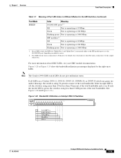
...Table 1-7 explains how to Figure 1-24 for the LRE switches. Solid green Link present. Port was powered on a logarithmic scale. ...switch for 10/100/1000 ports. 1. UTIL (utilization) Green The current backplane utilization that is sending or receiving data. The bandwidth in Different Modes for Non-LRE Switches Port Mode Color Meaning STAT (port status) Off No link. Chapter 1 Overview Front-Panel Description Table 1-5 Port Mode LEDs Mode LED Port Mode Description STAT UTIL1 Port status Switch utilization The port status. A Catalyst 2950 LRE switch...
...Table 1-7 explains how to Figure 1-24 for the LRE switches. Solid green Link present. Port was powered on a logarithmic scale. ...switch for 10/100/1000 ports. 1. UTIL (utilization) Green The current backplane utilization that is sending or receiving data. The bandwidth in Different Modes for Non-LRE Switches Port Mode Color Meaning STAT (port status) Off No link. Chapter 1 Overview Front-Panel Description Table 1-5 Port Mode LEDs Mode LED Port Mode Description STAT UTIL1 Port status Switch utilization The port status. A Catalyst 2950 LRE switch...
Hardware Installation Guide
Page 39
...Catalyst 2950 LRE switch LEDs do not give utilization status. Chapter 1 Overview Front-Panel Description Table 1-7 Meaning of Port LED Colors in Different Modes for Uplink Port 1 and Uplink Port 2 correspond either to the SFP module port or to the 10/100/1000 port, depending on . Green Port is operating at 10 Mbps. On an LRE switch, the LEDs for the LRE Switches (continued) Port... Utilization on a Catalyst 2950-12, 2950-24, 2950C-24, 2950SX-24, or 2950T-24 switch are green (no amber showing), the switch is active. 2. If all LEDs on Catalyst 2950-12 Switches SYST RPS STAT ...
...Catalyst 2950 LRE switch LEDs do not give utilization status. Chapter 1 Overview Front-Panel Description Table 1-7 Meaning of Port LED Colors in Different Modes for Uplink Port 1 and Uplink Port 2 correspond either to the SFP module port or to the 10/100/1000 port, depending on . Green Port is operating at 10 Mbps. On an LRE switch, the LEDs for the LRE Switches (continued) Port... Utilization on a Catalyst 2950-12, 2950-24, 2950C-24, 2950SX-24, or 2950T-24 switch are green (no amber showing), the switch is active. 2. If all LEDs on Catalyst 2950-12 Switches SYST RPS STAT ...

Hardware Installation Guide
Page 51
...Catalyst 2950ST-24 LRE 997 switch is within reach of a circuit breaker. - Return all 10/100 and 10/100/1000 ports must be easily read. - Four rubber feet for support. Front-panel DC power connector on switches other than the LRE switches is within reach of a circuit breaker. • Airflow around the switch... check each item for the Catalyst 2950 Switch • AC power cord (not shipped with the Catalyst 2950G-24-EI-DC switch or the Catalyst 2950ST-24 LRE 997 switch) • Console cable • Mounting kit containing these conditions: - The switch is within the ranges listed...
...Catalyst 2950ST-24 LRE 997 switch is within reach of a circuit breaker. - Return all 10/100 and 10/100/1000 ports must be easily read. - Four rubber feet for support. Front-panel DC power connector on switches other than the LRE switches is within reach of a circuit breaker. • Airflow around the switch... check each item for the Catalyst 2950 Switch • AC power cord (not shipped with the Catalyst 2950G-24-EI-DC switch or the Catalyst 2950ST-24 LRE 997 switch) • Console cable • Mounting kit containing these conditions: - The switch is within the ranges listed...
Hardware Installation Guide
Page 73
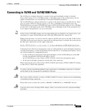
...-01 Catalyst 2950 Switch Hardware Installation Guide 2-27 Chapter 2 Installation Connecting to 10/100 and 10/100/1000 Ports Connecting to 10/100 and 10/100/1000 Ports The 10/100 ports configure themselves to operate at 10 or 100 Mbps in half- If the Catalyst 2950 LRE switch senses more than two connections for more information on both speed and duplex, and let the 10/100/1000 ports on the Catalyst 2950G-24-EI-DC switch...
...-01 Catalyst 2950 Switch Hardware Installation Guide 2-27 Chapter 2 Installation Connecting to 10/100 and 10/100/1000 Ports Connecting to 10/100 and 10/100/1000 Ports The 10/100 ports configure themselves to operate at 10 or 100 Mbps in half- If the Catalyst 2950 LRE switch senses more than two connections for more information on both speed and duplex, and let the 10/100/1000 ports on the Catalyst 2950G-24-EI-DC switch...
Hardware Installation Guide
Page 74
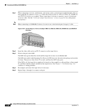
...-through 4 to cabling problems. Reconfigure and restart the target device if necessary. Figure 2-35 shows the Catalyst 2950-12, 2950-24, 2950C-24, 2950SX-24, and 2950T-24 switch as an example. When connecting to use a four twisted-pair, Category 5 cable. If the LED is... to connect each port. 2-28 Catalyst 2950 Switch Hardware Installation Guide OL-6156-01 Observe the port status LED. Figure 2-35 Connecting to a Port on page B-6 for loops. Repeat Steps 1 through cable in a front-panel RJ-45 connector. Connecting to 10/100 and 10/100/1000 Ports Chapter 2 Installation ...
...-through 4 to cabling problems. Reconfigure and restart the target device if necessary. Figure 2-35 shows the Catalyst 2950-12, 2950-24, 2950C-24, 2950SX-24, and 2950T-24 switch as an example. When connecting to use a four twisted-pair, Category 5 cable. If the LED is... to connect each port. 2-28 Catalyst 2950 Switch Hardware Installation Guide OL-6156-01 Observe the port status LED. Figure 2-35 Connecting to a Port on page B-6 for loops. Repeat Steps 1 through cable in a front-panel RJ-45 connector. Connecting to 10/100 and 10/100/1000 Ports Chapter 2 Installation ...
Hardware Installation Guide
Page 100
If the Catalyst 2950 LRE switch senses more information on Catalyst 2950T-24, Catalyst 2950T-48-SI, and Catalyst 2950 Long-Reach Ethernet (LRE) switches use a two or four twisted-pair, crossover cable. Use a crossover cable to 10BASE-T devices. Figure B-10 shows the two twisted-pair, straight-... Use a straight-through cable to 100BASE-TX devices. Note On the Catalyst 2950 LRE switches, the four input uplink ports are designated with an X. Within each consisting of a copper 10/100/1000 port and a fiber-optic small form-factor pluggable (SFP) module slot, respectively...
If the Catalyst 2950 LRE switch senses more information on Catalyst 2950T-24, Catalyst 2950T-48-SI, and Catalyst 2950 Long-Reach Ethernet (LRE) switches use a two or four twisted-pair, crossover cable. Use a crossover cable to 10BASE-T devices. Figure B-10 shows the two twisted-pair, straight-... Use a straight-through cable to 100BASE-TX devices. Note On the Catalyst 2950 LRE switches, the four input uplink ports are designated with an X. Within each consisting of a copper 10/100/1000 port and a fiber-optic small form-factor pluggable (SFP) module slot, respectively...

Hardware Installation Guide
Page 106
... the schematics of four twisted-pair cables for 10/100/1000 ports on the Catalyst 2950ST-24 LRE and Catalyst 2950ST-24 LRE 997 switches. Table B-1 Catalyst 2950ST-24 LRE and Catalyst 2950ST-24 LRE 997 Switch RJ-21 Cable Pinouts Function Port 1 Tip Port 2 Tip Port 3 Tip Port 4 Tip Pin Pin Function 1 26 Port 1 Ring 2 27 Port 2 Ring 3 28 Port 3 Ring 4 29 Port 4 Ring Catalyst 2950 Switch Hardware Installation Guide B-8 OL-6156-01
... the schematics of four twisted-pair cables for 10/100/1000 ports on the Catalyst 2950ST-24 LRE and Catalyst 2950ST-24 LRE 997 switches. Table B-1 Catalyst 2950ST-24 LRE and Catalyst 2950ST-24 LRE 997 Switch RJ-21 Cable Pinouts Function Port 1 Tip Port 2 Tip Port 3 Tip Port 4 Tip Pin Pin Function 1 26 Port 1 Ring 2 27 Port 2 Ring 3 28 Port 3 Ring 4 29 Port 4 Ring Catalyst 2950 Switch Hardware Installation Guide B-8 OL-6156-01

Hardware Installation Guide
Page 128
... pinout B-6 twisted-pair 10/100/1000 ports 2-8 10/100 ports 2-7 to 2-8 See also connectors and cables Catalyst 2950G-24-EI-DC service warning C-1 Catalyst 2950ST-24 LRE 997 service warning C-1 cautions, defined x chassis warnings rack-mounting, servicing 3-7 Cisco IE2100 2-25 Cisco IE2100 Series Configuration Registrar See Cisco IE2100 IN-2 Catalyst 2950 Switch Hardware Installation Guide Cisco Intelligent Engine 2100 See Cisco IE2100 CiscoView 2-24 clearance 3-5 CLI 2-24 accessing by using...
... pinout B-6 twisted-pair 10/100/1000 ports 2-8 10/100 ports 2-7 to 2-8 See also connectors and cables Catalyst 2950G-24-EI-DC service warning C-1 Catalyst 2950ST-24 LRE 997 service warning C-1 cautions, defined x chassis warnings rack-mounting, servicing 3-7 Cisco IE2100 2-25 Cisco IE2100 Series Configuration Registrar See Cisco IE2100 IN-2 Catalyst 2950 Switch Hardware Installation Guide Cisco Intelligent Engine 2100 See Cisco IE2100 CiscoView 2-24 clearance 3-5 CLI 2-24 accessing by using...
Hardware Installation Guide
Page 129
...10/100 ports B-7 four twisted-pair, 1000BASE-T ports B-8 two twisted-pair B-6 CWDM GBIC modules cable lengths 3-4 connecting to 3-35 described 2-10 installing 3-22 D DC power connecting to C-1 to C-7 connector 2-23 specifications A-2, A-4 warnings C-1 to C-4 desk-mounting 3-17 OL-6156-01 Index Device Manager xvi description 2-24 to configure switch...to Cisco Systems, web xviii fiber-optic port specifications A-5 front panel 10/100/1000 ports 2-8 10/100 ports 2-7 to 2-8 1000BASE-SX ports 2-9 100BASE-FX ports 2-9 clearance 3-5 described 2-3 Catalyst 2950 Switch Hardware Installation Guide IN-3
...10/100 ports B-7 four twisted-pair, 1000BASE-T ports B-8 two twisted-pair B-6 CWDM GBIC modules cable lengths 3-4 connecting to 3-35 described 2-10 installing 3-22 D DC power connecting to C-1 to C-7 connector 2-23 specifications A-2, A-4 warnings C-1 to C-4 desk-mounting 3-17 OL-6156-01 Index Device Manager xvi description 2-24 to configure switch...to Cisco Systems, web xviii fiber-optic port specifications A-5 front panel 10/100/1000 ports 2-8 10/100 ports 2-7 to 2-8 1000BASE-SX ports 2-9 100BASE-FX ports 2-9 clearance 3-5 described 2-3 Catalyst 2950 Switch Hardware Installation Guide IN-3

Hardware Installation Guide
Page 131
... A-4 pinouts 10/100/1000 ports B-3 10/100 ports B-2 1000BASE-T GBIC port B-4 console port DB-25 adapter B-11 RJ-45-to-DB-9 adapter cable B-10 crossover cables four twisted-pair, 10/100 ports B-7 four twisted-pair, 1000BASE-T ports B-8 two twisted-pair B-6 DB-25 adapters B-11 RJ-21 connector B-8 to B-10 RJ-45-to-DB-25 terminal adapter B-11 RJ-45-to-DB-9 adapter cable B-10 Catalyst 2950 Switch Hardware...
... A-4 pinouts 10/100/1000 ports B-3 10/100 ports B-2 1000BASE-T GBIC port B-4 console port DB-25 adapter B-11 RJ-45-to-DB-9 adapter cable B-10 crossover cables four twisted-pair, 10/100 ports B-7 four twisted-pair, 1000BASE-T ports B-8 two twisted-pair B-6 DB-25 adapters B-11 RJ-21 connector B-8 to B-10 RJ-45-to-DB-25 terminal adapter B-11 RJ-45-to-DB-9 adapter cable B-10 Catalyst 2950 Switch Hardware...
Hardware Installation Guide
Page 132
...10 straight-through cables four twisted-pair, 10/100 ports B-7 four twisted-pair, 1000BASE-T ports B-8 two twisted-pair B-6 port LEDs 2-13 to 2-15, 2-16 mode LEDs 2-13 to 2-15, 2-16 to 2-18 selecting 2-16 ports See 10/100 ports, 10/100/1000 ports, 100BASE-FX ports, 1000BASE-SX, GBIC module ports, LRE, and console ports... 3-40 publications, related xv to xvi IN-6 Catalyst 2950 Switch Hardware Installation Guide R rack-mounting bracket mounting points 3-8 to 3-15 procedures 3-7 to 3-16 warning 3-7 rear panel clearance 3-5 console port connector 2-24 described 2-21 to 2-22 illustrated 2-21 to ...
...10 straight-through cables four twisted-pair, 10/100 ports B-7 four twisted-pair, 1000BASE-T ports B-8 two twisted-pair B-6 port LEDs 2-13 to 2-15, 2-16 mode LEDs 2-13 to 2-15, 2-16 to 2-18 selecting 2-16 ports See 10/100 ports, 10/100/1000 ports, 100BASE-FX ports, 1000BASE-SX, GBIC module ports, LRE, and console ports... 3-40 publications, related xv to xvi IN-6 Catalyst 2950 Switch Hardware Installation Guide R rack-mounting bracket mounting points 3-8 to 3-15 procedures 3-7 to 3-16 warning 3-7 rear panel clearance 3-5 console port connector 2-24 described 2-21 to 2-22 illustrated 2-21 to ...

Hardware Installation Guide
Page 133
... technical specifications A-1 to A-7 Telnet, and accessing the CLI 2-24 temperature operating A-1 to A-4 terminal-emulation software D-4 troubleshooting diagnosing problems 4-1 to 4-3 understanding POST results 4-1 OL-6156-01 Index U uplink ports, LRE 2-9 URLs, Cisco xvii utilization bandwidth 2-17 to 2-21 LED 2-17 V verifying package contents 3-5 to 3-6 W warnings DC power C-1 to C-4 installation 3-1 to 3-4 Catalyst 2950 Switch Hardware Installation Guide IN-7
... technical specifications A-1 to A-7 Telnet, and accessing the CLI 2-24 temperature operating A-1 to A-4 terminal-emulation software D-4 troubleshooting diagnosing problems 4-1 to 4-3 understanding POST results 4-1 OL-6156-01 Index U uplink ports, LRE 2-9 URLs, Cisco xvii utilization bandwidth 2-17 to 2-21 LED 2-17 V verifying package contents 3-5 to 3-6 W warnings DC power C-1 to C-4 installation 3-1 to 3-4 Catalyst 2950 Switch Hardware Installation Guide IN-7


