

Hardware Installation Guide
Page 5
...-X GBIC Module Ports B-4 1000BASE-T GBIC Module Ports B-4 GigaStack GBIC Module Ports B-4 SFP Module Ports B-5 Console Port B-5 Identifying a Crossover Cable B-5 Cable and Adapter Specifications B-6 Two Twisted-Pair Cable Pinouts B-6 Four Twisted-Pair Cable Pinouts for 10/100 Ports B-7 Four Twisted-Pair Cable Pinouts for 1000BASE-T Ports B-8 RJ-21 Cable Pinouts B-8 Adapter Pinouts B-10 Contents OL-6156-01 Catalyst 2950 Switch Hardware Installation...
...-X GBIC Module Ports B-4 1000BASE-T GBIC Module Ports B-4 GigaStack GBIC Module Ports B-4 SFP Module Ports B-5 Console Port B-5 Identifying a Crossover Cable B-5 Cable and Adapter Specifications B-6 Two Twisted-Pair Cable Pinouts B-6 Four Twisted-Pair Cable Pinouts for 10/100 Ports B-7 Four Twisted-Pair Cable Pinouts for 1000BASE-T Ports B-8 RJ-21 Cable Pinouts B-8 Adapter Pinouts B-10 Contents OL-6156-01 Catalyst 2950 Switch Hardware Installation...

Hardware Installation Guide
Page 31
... to 1550 nanometers (nm). See the Catalyst 2950 LRE switch release notes for reliable communications, the cable must match the wave-length specifications on the front of the two physical ports, either the SFP module port or the 10/100/1000 port on Uplink Port 2. If you can configure the Catalyst 2950 LRE switch so that scenario, whichever media type establishes...
... to 1550 nanometers (nm). See the Catalyst 2950 LRE switch release notes for reliable communications, the cable must match the wave-length specifications on the front of the two physical ports, either the SFP module port or the 10/100/1000 port on Uplink Port 2. If you can configure the Catalyst 2950 LRE switch so that scenario, whichever media type establishes...

Hardware Installation Guide
Page 32
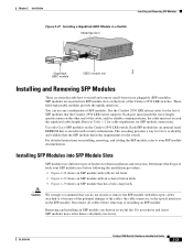
...more information about these SFP modules, see your SFP module documentation. 1-12 Catalyst 2950 Switch Hardware Installation Guide OL-6156-01 Note When using a non-Cisco approved SFP module, remove the module from the switch, and replace it with 62.5-micron diameter MMF, you might need to... 100 km)2 1. When the fiber-optic cable span is required. Front-Panel Description Chapter 1 Overview Table 1-2 Fiber-Optic SFP Module Port Cabling Specifications ...
...more information about these SFP modules, see your SFP module documentation. 1-12 Catalyst 2950 Switch Hardware Installation Guide OL-6156-01 Note When using a non-Cisco approved SFP module, remove the module from the switch, and replace it with 62.5-micron diameter MMF, you might need to... 100 km)2 1. When the fiber-optic cable span is required. Front-Panel Description Chapter 1 Overview Table 1-2 Fiber-Optic SFP Module Port Cabling Specifications ...
Hardware Installation Guide
Page 44
...port and the supplied RJ-45-to-DB-9 adapter cable. you need a web browser to run on page B-6. For more information, see the Getting Started with your SNMP application. 1-24 Catalyst 2950 Switch Hardware Installation Guide OL-6156-01 This application, which is a GUI-based application that came with Cisco... go to Appendix D, "Configuring the Switch with your desktop; The device manager page appears. You can manage switches by using command-line entries. For more information, see the "Cable and Adapter Specifications" section on your CiscoView application. &#...
...port and the supplied RJ-45-to-DB-9 adapter cable. you need a web browser to run on page B-6. For more information, see the Getting Started with your SNMP application. 1-24 Catalyst 2950 Switch Hardware Installation Guide OL-6156-01 This application, which is a GUI-based application that came with Cisco... go to Appendix D, "Configuring the Switch with your desktop; The device manager page appears. You can manage switches by using command-line entries. For more information, see the "Cable and Adapter Specifications" section on your CiscoView application. &#...

Hardware Installation Guide
Page 50
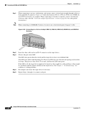
...For specific cable lengths, see the CWDM GBIC module documentation. Statement 1017 Warning Ethernet cables must be shielded when used in the "Verifying Switch Operation" section on page 2-6. • For 10/100 ports and 10/100/1000 ports, the cable length from a switch to... terminals on the chassis. Catalyst 2950 Switch Hardware Installation Guide 2-4 OL-6156-01 Statement 88 Installation Guidelines When determining where to place the switch, observe these guidelines. • Before installing the switch, first verify that services the DC circuit, switch the circuit breaker to be...
...For specific cable lengths, see the CWDM GBIC module documentation. Statement 1017 Warning Ethernet cables must be shielded when used in the "Verifying Switch Operation" section on page 2-6. • For 10/100 ports and 10/100/1000 ports, the cable length from a switch to... terminals on the chassis. Catalyst 2950 Switch Hardware Installation Guide 2-4 OL-6156-01 Statement 88 Installation Guidelines When determining where to place the switch, observe these guidelines. • Before installing the switch, first verify that services the DC circuit, switch the circuit breaker to be...

Hardware Installation Guide
Page 51
... missing or damaged, contact your Cisco representative or reseller for damage. Four rubber feet for unrestricted cabling. - Access to an attached device cannot exceed 3 feet (1 meter). • For Long-Reach Ethernet (LRE) ports, cable-length specifications vary. Two 19-inch or 24-inch rack-mounting brackets OL-6156-01 Catalyst 2950 Switch Hardware Installation Guide 2-5 If any...
... missing or damaged, contact your Cisco representative or reseller for damage. Four rubber feet for unrestricted cabling. - Access to an attached device cannot exceed 3 feet (1 meter). • For Long-Reach Ethernet (LRE) ports, cable-length specifications vary. Two 19-inch or 24-inch rack-mounting brackets OL-6156-01 Catalyst 2950 Switch Hardware Installation Guide 2-5 If any...
Hardware Installation Guide
Page 69
.... OL-6156-01 Catalyst 2950 Switch Hardware Installation Guide 2-23 See the Catalyst 2950 LRE release notes for the list of latches for the switch. This encoding provides a way for Cisco to Table 1-2 for cable stipulations for reliable communications, the cable must not exceed the stipulated cable length. Each port must match the wave-length specifications on installing, removing...
.... OL-6156-01 Catalyst 2950 Switch Hardware Installation Guide 2-23 See the Catalyst 2950 LRE release notes for the list of latches for the switch. This encoding provides a way for Cisco to Table 1-2 for cable stipulations for reliable communications, the cable must not exceed the stipulated cable length. Each port must match the wave-length specifications on installing, removing...
Hardware Installation Guide
Page 74
...through cable in a front-panel RJ-45 connector. If the LED is off, the target device might not be turned on Catalyst 2950-12, 2950-24, 2950C-24, 2950SX-24, and 2950T-24 Switches SYST RPS STAT UTIL DUPLX SPEED MODE 1x 2x 3x 4x 5x 45576 Step 2 Step 3 Step 4 Step 5 Insert the...2-35 Connecting to a Port on , there might be a cable problem, or there might be sure to cabling problems. Reconfigure and restart the target device if necessary. When connecting to switches or repeaters, insert a twisted-pair crossover cable. (See the "Cable and Adapter Specifications" section on the target...
...through cable in a front-panel RJ-45 connector. If the LED is off, the target device might not be turned on Catalyst 2950-12, 2950-24, 2950C-24, 2950SX-24, and 2950T-24 Switches SYST RPS STAT UTIL DUPLX SPEED MODE 1x 2x 3x 4x 5x 45576 Step 2 Step 3 Step 4 Step 5 Insert the...2-35 Connecting to a Port on , there might be a cable problem, or there might be sure to cabling problems. Reconfigure and restart the target device if necessary. When connecting to switches or repeaters, insert a twisted-pair crossover cable. (See the "Cable and Adapter Specifications" section on the target...
Hardware Installation Guide
Page 77
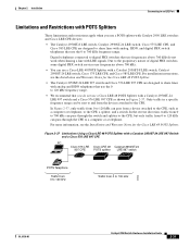
...Cisco LRE 48 POTS Splitter with a Catalyst 2950ST-24 LRE 997 Switch and a Cisco 576 LRE 997 CPE PC Cisco 576 LRE Cisco LRE 48 Catalyst 2950ST-24 997 CPE POTS splitter LRE 997 switch POTS Telephone Traffic from 0 to 120 kHz Traffic from a device attached to the CPE, such as shown in a specific... LRE Port Limitations and Restrictions with POTS Splitters These limitations and restrictions apply when you use a POTS splitter with Catalyst 2950 LRE switches and Cisco LRE CPE devices: • The Catalyst 2950ST-8 LRE switch, Catalyst 2950ST-24 LRE switch, Cisco 575 LRE CPE, and Cisco 585 LRE...
...Cisco LRE 48 POTS Splitter with a Catalyst 2950ST-24 LRE 997 Switch and a Cisco 576 LRE 997 CPE PC Cisco 576 LRE Cisco LRE 48 Catalyst 2950ST-24 997 CPE POTS splitter LRE 997 switch POTS Telephone Traffic from 0 to 120 kHz Traffic from a device attached to the CPE, such as shown in a specific... LRE Port Limitations and Restrictions with POTS Splitters These limitations and restrictions apply when you use a POTS splitter with Catalyst 2950 LRE switches and Cisco LRE CPE devices: • The Catalyst 2950ST-8 LRE switch, Catalyst 2950ST-24 LRE switch, Cisco 575 LRE CPE, and Cisco 585 LRE...

Hardware Installation Guide
Page 89
... was used when a straight-through cables, see the switch software configuration guide. • Check if the fan has failed by using the show post privileged EXEC command to turn green. If the fan has failed, call Cisco Systems. • Use the show env fan privileged... OL-6156-01 Catalyst 2950 Switch Hardware Installation Guide 3-3 Unreadable characters on page B-6. • Replace it with a tested good cable. • Wait 30 seconds for more information, see the "Cable and Adapter Specifications" section on the management console. System LED is amber, and all port LEDs are off....
... was used when a straight-through cables, see the switch software configuration guide. • Check if the fan has failed by using the show post privileged EXEC command to turn green. If the fan has failed, call Cisco Systems. • Use the show env fan privileged... OL-6156-01 Catalyst 2950 Switch Hardware Installation Guide 3-3 Unreadable characters on page B-6. • Replace it with a tested good cable. • Wait 30 seconds for more information, see the "Cable and Adapter Specifications" section on the management console. System LED is amber, and all port LEDs are off....

Hardware Installation Guide
Page 91
... uplink ports. Table A-6 lists the technical specifications for the switches other than the Catalyst 2950 Long-Reach Ethernet (LRE) switches. A A P P E N D I X Technical Specifications OL-6156-01 Table A-1 through Table A-5 list the technical specifications for the Cisco RPS2 300 Redundant Power System 100 to 127/200 to 240 VAC (autoranging) 50 to 15,000 ft (4570 m) 84 in . (4.36 x 44.45 x 24...
... uplink ports. Table A-6 lists the technical specifications for the switches other than the Catalyst 2950 Long-Reach Ethernet (LRE) switches. A A P P E N D I X Technical Specifications OL-6156-01 Table A-1 through Table A-5 list the technical specifications for the Cisco RPS2 300 Redundant Power System 100 to 127/200 to 240 VAC (autoranging) 50 to 15,000 ft (4570 m) 84 in . (4.36 x 44.45 x 24...
Hardware Installation Guide
Page 95
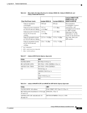
SFP = small form-factor pluggable 3. Appendix A Technical Specifications Table A-6 Fiber-Optic Port Specifications for Catalyst 2950C-24, Catalyst 2950SX-24, and Catalyst 2950 LRE Switches Fiber-Port Power Levels Catalyst 2950C-24 Optical transmitter wavelength 1300 nm1 Optical receiver sensitivity -33.5 to for 50/125-micron cabling -11.8 dBm3 Optical receiver sensitivity -33.5 to for 62.5/125-...
SFP = small form-factor pluggable 3. Appendix A Technical Specifications Table A-6 Fiber-Optic Port Specifications for Catalyst 2950C-24, Catalyst 2950SX-24, and Catalyst 2950 LRE Switches Fiber-Port Power Levels Catalyst 2950C-24 Optical transmitter wavelength 1300 nm1 Optical receiver sensitivity -33.5 to for 50/125-micron cabling -11.8 dBm3 Optical receiver sensitivity -33.5 to for 62.5/125-...

Hardware Installation Guide
Page 99
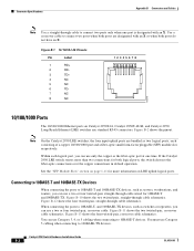
... routers, you can use Category 5 cabling when connecting to the port. Connector Specifications These sections describe the connectors used with internal crossovers, as switches or repeaters, you can be attached to 100BASE-TX devices. Figure...Catalyst 2950 switches and contains this information: • 10/100 Ports, page B-1 • 10/100/1000 Ports, page B-2 • 100BASE-FX and 1000BASE-SX Ports, page B-4 • LRE Port, page B-3 • GigaStack GBIC Module Ports, page B-4 • SFP Module Ports, page B-5 • Console Port, page B-5 10/100 Ports The 10/100 Ethernet ports...
... routers, you can use Category 5 cabling when connecting to the port. Connector Specifications These sections describe the connectors used with internal crossovers, as switches or repeaters, you can be attached to 100BASE-TX devices. Figure...Catalyst 2950 switches and contains this information: • 10/100 Ports, page B-1 • 10/100/1000 Ports, page B-2 • 100BASE-FX and 1000BASE-SX Ports, page B-4 • LRE Port, page B-3 • GigaStack GBIC Module Ports, page B-4 • SFP Module Ports, page B-5 • Console Port, page B-5 10/100 Ports The 10/100 Ethernet ports...
Hardware Installation Guide
Page 100
... crossover cable schematics. Connector Specifications Appendix B Connectors and Cables Note Use a straight-through cable to connect two ports only when one time. Use a crossover cable to connect two ports when both ports are bundled as two logical ports, each logical port, you can use a two...H5318 10/100/1000 Ports The 10/100/1000 Ethernet ports on Catalyst 2950T-24, Catalyst 2950T-48-SI, and Catalyst 2950 Long-Reach Ethernet (LRE) switches use only the copper or the fiber-optic port at one port is designated with an X or when both logical ports, the switch chooses the fiber-optic...
... crossover cable schematics. Connector Specifications Appendix B Connectors and Cables Note Use a straight-through cable to connect two ports only when one time. Use a crossover cable to connect two ports when both ports are bundled as two logical ports, each logical port, you can use a two...H5318 10/100/1000 Ports The 10/100/1000 Ethernet ports on Catalyst 2950T-24, Catalyst 2950T-48-SI, and Catalyst 2950 Long-Reach Ethernet (LRE) switches use only the copper or the fiber-optic port at one port is designated with an X or when both logical ports, the switch chooses the fiber-optic...

Hardware Installation Guide
Page 104
... B Connectors and Cables Pin 8 H10632 Cable and Adapter Specifications These sections describe the cables and adapters used with Catalyst 2950 switches. • Two Twisted-Pair Cable Pinouts, page B-6 • Four Twisted-Pair Cable Pinouts for 10/100 Ports, page B-7 • Four Twisted-Pair Cable Pinouts for 1000BASE-T Ports, page B-8 • RJ-21 Cable Pinouts, page B-8 Two...
... B Connectors and Cables Pin 8 H10632 Cable and Adapter Specifications These sections describe the cables and adapters used with Catalyst 2950 switches. • Two Twisted-Pair Cable Pinouts, page B-6 • Four Twisted-Pair Cable Pinouts for 10/100 Ports, page B-7 • Four Twisted-Pair Cable Pinouts for 1000BASE-T Ports, page B-8 • RJ-21 Cable Pinouts, page B-8 Two...

Hardware Installation Guide
Page 105
... Crossover Cable Schematic for 10/100 Ports Switch 1 RD+ 2 RD3 TD+ 6 TD- Switch 1 RD+ 2 RD3 TD+ 6 TD- 4 NC 5 NC 7 NC 8 NC 4 NC 5 NC 7 NC 8 NC 65273 OL-6156-01 Catalyst 2950 Switch Hardware Installation Guide B-7 Appendix B Connectors and Cables Cable and Adapter Specifications Four Twisted-Pair Cable Pinouts for 10/100 Ports Figure B-12 and Figure B-13 show...
... Crossover Cable Schematic for 10/100 Ports Switch 1 RD+ 2 RD3 TD+ 6 TD- Switch 1 RD+ 2 RD3 TD+ 6 TD- 4 NC 5 NC 7 NC 8 NC 4 NC 5 NC 7 NC 8 NC 65273 OL-6156-01 Catalyst 2950 Switch Hardware Installation Guide B-7 Appendix B Connectors and Cables Cable and Adapter Specifications Four Twisted-Pair Cable Pinouts for 10/100 Ports Figure B-12 and Figure B-13 show...

Hardware Installation Guide
Page 106
... Switch RJ-21 Cable Pinouts Function Port 1 Tip Port 2 Tip Port 3 Tip Port 4 Tip Pin Pin Function 1 26 Port 1 Ring 2 27 Port 2 Ring 3 28 Port 3 Ring 4 29 Port 4 Ring Catalyst 2950 Switch Hardware Installation Guide B-8 OL-6156-01 Figure B-14 Four Twisted-Pair Straight-Through Cable Schematic for 10/100/1000 and 1000BASE-T GBIC Module Ports Switch 1 TPO+ 2 TPO3 TP1+ 6 TP1- Cable and Adapter Specifications...
... Switch RJ-21 Cable Pinouts Function Port 1 Tip Port 2 Tip Port 3 Tip Port 4 Tip Pin Pin Function 1 26 Port 1 Ring 2 27 Port 2 Ring 3 28 Port 3 Ring 4 29 Port 4 Ring Catalyst 2950 Switch Hardware Installation Guide B-8 OL-6156-01 Figure B-14 Four Twisted-Pair Straight-Through Cable Schematic for 10/100/1000 and 1000BASE-T GBIC Module Ports Switch 1 TPO+ 2 TPO3 TP1+ 6 TP1- Cable and Adapter Specifications...

Configuration Guide
Page 56
...policy maps.6 Display the most recent system messages (IOS messages and switch-specific messages) sent by the switch. Configure a port to VLANs, and configure 802.1Q trunks. Display port statistics. If one device is a Catalyst 2950 switch running Cisco IOS Release 12.1(6)EA2 or later. Display graphs that plot the ...total bandwidth in a cluster where the command switch is an unknown device or a candidate, only the ...
...policy maps.6 Display the most recent system messages (IOS messages and switch-specific messages) sent by the switch. Configure a port to VLANs, and configure 802.1Q trunks. Display port statistics. If one device is a Catalyst 2950 switch running Cisco IOS Release 12.1(6)EA2 or later. Display graphs that plot the ...total bandwidth in a cluster where the command switch is an unknown device or a candidate, only the ...

Configuration Guide
Page 367
... icon 2-22 multi-VLAN ports VLAN membership combinations 8-6 MVR configuring interfaces 11-12 default configuration 11-10 description 11-7 modes 11-11 monitoring 11-14 setting global parameters 11-10 N named IP ACLs 12-12 native VLANs 8-24 NCPs 6-22 negotiate trunk ... domain 8-10 path cost 8-27 path cost, STP 9-25 PC (passive command switch) 5-10, 5-20 per-VLAN Spanning Tree (PVST) 9-2 per-VLAN Spanning Tree+ (PVST+) 9-8 planning considerations, switch clusters LRE profiles 5-16 management VLAN 5-15 switch-specific features 5-16 Catalyst 2950 Desktop Switch Software Configuration Guide IN-13
... icon 2-22 multi-VLAN ports VLAN membership combinations 8-6 MVR configuring interfaces 11-12 default configuration 11-10 description 11-7 modes 11-11 monitoring 11-14 setting global parameters 11-10 N named IP ACLs 12-12 native VLANs 8-24 NCPs 6-22 negotiate trunk ... domain 8-10 path cost 8-27 path cost, STP 9-25 PC (passive command switch) 5-10, 5-20 per-VLAN Spanning Tree (PVST) 9-2 per-VLAN Spanning Tree+ (PVST+) 9-8 planning considerations, switch clusters LRE profiles 5-16 management VLAN 5-15 switch-specific features 5-16 Catalyst 2950 Desktop Switch Software Configuration Guide IN-13

Configuration Guide
Page 373
...described 9-11 SunNet Manager 1-7 switch clustering technology 5-1 switch clusters planning considerations LRE profiles 5-16 management VLAN 5-15 switch-specific features 5-16 Switch Manager 2-2, 2-33 See also Device Manager Switch Port Analyzer see SPAN switchport command 8-22 switch ports, configuring 10-1 switch priority, STP 9-26 switch software releases 4-2 78-11380-03 switch-to-client frame retransmission number ...-server host command 6-20, 6-21 tacacs-server retransmit command 6-21, 6-23 tacacs-server timeout command 6-21 Catalyst 2950 Desktop Switch Software Configuration Guide IN-19
...described 9-11 SunNet Manager 1-7 switch clustering technology 5-1 switch clusters planning considerations LRE profiles 5-16 management VLAN 5-15 switch-specific features 5-16 Switch Manager 2-2, 2-33 See also Device Manager Switch Port Analyzer see SPAN switchport command 8-22 switch ports, configuring 10-1 switch priority, STP 9-26 switch software releases 4-2 78-11380-03 switch-to-client frame retransmission number ...-server host command 6-20, 6-21 tacacs-server retransmit command 6-21, 6-23 tacacs-server timeout command 6-21 Catalyst 2950 Desktop Switch Software Configuration Guide IN-19


