

Hardware Installation Guide
Page 3
... Overview 1-1 Setting up the Switch 1-1 Features 1-1 Front-Panel Description 1-3 10/100 Ports 1-7 10/100/1000 Ports 1-8 100BASE-FX and 1000BASE-SX Ports 1-9 LRE Port 1-9 GBIC Module Ports 1-10 SFP Module Slots 1-11 SFP Modules 1-11 LEDs 1-13 System LED 1-16 RPS LED 1-16 Port Mode and Port Status LEDs 1-16 CONTENTS OL-6156-01 Catalyst 2950 Switch Hardware Installation Guide iii
... Overview 1-1 Setting up the Switch 1-1 Features 1-1 Front-Panel Description 1-3 10/100 Ports 1-7 10/100/1000 Ports 1-8 100BASE-FX and 1000BASE-SX Ports 1-9 LRE Port 1-9 GBIC Module Ports 1-10 SFP Module Slots 1-11 SFP Modules 1-11 LEDs 1-13 System LED 1-16 RPS LED 1-16 Port Mode and Port Status LEDs 1-16 CONTENTS OL-6156-01 Catalyst 2950 Switch Hardware Installation Guide iii
Hardware Installation Guide
Page 4
... Cisco RPS Connector 1-23 Console Port 1-24 Management Options 1-24 Installation 2-1 Preparing for Installation 2-1 Warnings 2-1 Installation Guidelines 2-4 Verifying Package Contents 2-5 Verifying Switch Operation 2-6 Installing the Switch 2-7 Installing the Switch in a Rack 2-7 Attaching the Brackets to the Switch 2-8 Mounting the Switch in...Switch on a Table, Shelf, or Desk 2-17 Installing the Switch on a Wall 2-17 Attaching the Brackets to the Switch 2-17 Attaching the RPS Connector Cover 2-18 Mounting the Switch to a Wall 2-18 Installing the Optional AC Ground Kit for Catalyst 2950 Switches...
... Cisco RPS Connector 1-23 Console Port 1-24 Management Options 1-24 Installation 2-1 Preparing for Installation 2-1 Warnings 2-1 Installation Guidelines 2-4 Verifying Package Contents 2-5 Verifying Switch Operation 2-6 Installing the Switch 2-7 Installing the Switch in a Rack 2-7 Attaching the Brackets to the Switch 2-8 Mounting the Switch in...Switch on a Table, Shelf, or Desk 2-17 Installing the Switch on a Wall 2-17 Attaching the Brackets to the Switch 2-17 Attaching the RPS Connector Cover 2-18 Mounting the Switch to a Wall 2-18 Installing the Optional AC Ground Kit for Catalyst 2950 Switches...

Hardware Installation Guide
Page 5
... Ports B-4 1000BASE-X GBIC Module Ports B-4 1000BASE-T GBIC Module Ports B-4 GigaStack GBIC Module Ports B-4 SFP Module Ports B-5 Console Port B-5 Identifying a Crossover Cable B-5 Cable and Adapter Specifications B-6 Two Twisted-Pair Cable Pinouts B-6 Four Twisted-Pair Cable Pinouts for 10/100 Ports B-7 Four Twisted-Pair Cable Pinouts for 1000BASE-T Ports B-8 RJ-21 Cable Pinouts B-8 Adapter Pinouts B-10 Contents OL-6156-01 Catalyst 2950 Switch...
... Ports B-4 1000BASE-X GBIC Module Ports B-4 1000BASE-T GBIC Module Ports B-4 GigaStack GBIC Module Ports B-4 SFP Module Ports B-5 Console Port B-5 Identifying a Crossover Cable B-5 Cable and Adapter Specifications B-6 Two Twisted-Pair Cable Pinouts B-6 Four Twisted-Pair Cable Pinouts for 10/100 Ports B-7 Four Twisted-Pair Cable Pinouts for 1000BASE-T Ports B-8 RJ-21 Cable Pinouts B-8 Adapter Pinouts B-10 Contents OL-6156-01 Catalyst 2950 Switch...

Hardware Installation Guide
Page 6
... the CLI D-1 Accessing the CLI Through Express Setup D-1 Accessing the CLI Through the Console Port D-2 Taking Out What You Need D-3 Connecting to the Console Port D-3 Starting the Terminal-Emulation Software D-4 Connecting to a Power Source D-5 Entering the Initial Configuration Information D-5 IP Settings D-5 Completing the Setup Program D-6 Catalyst 2950 Switch Hardware Installation Guide vi OL-6156-01
... the CLI D-1 Accessing the CLI Through Express Setup D-1 Accessing the CLI Through the Console Port D-2 Taking Out What You Need D-3 Connecting to the Console Port D-3 Starting the Terminal-Emulation Software D-4 Connecting to a Power Source D-5 Entering the Initial Configuration Information D-5 IP Settings D-5 Completing the Setup Program D-6 Catalyst 2950 Switch Hardware Installation Guide vi OL-6156-01
Hardware Installation Guide
Page 21
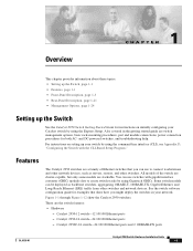
..., Gigabit Ethernet, and Long-Reach Ethernet (LRE) traffic from other switches. Catalyst 2950-24 switch-24 10/100 Ethernet ports - Some switch models can use switches with the CLI-Based Setup Program." Catalyst 2950-12 switch-12 10/100 Ethernet ports - Also covered in your Catalyst switch by using the Express Setup. Catalyst 2950C-24 switch-24 10/100 Ethernet ports and 2 100BASE-FX ports OL-6156-01 Catalyst 2950 Switch Hardware Installation Guide 1-1
..., Gigabit Ethernet, and Long-Reach Ethernet (LRE) traffic from other switches. Catalyst 2950-24 switch-24 10/100 Ethernet ports - Some switch models can use switches with the CLI-Based Setup Program." Catalyst 2950-12 switch-12 10/100 Ethernet ports - Also covered in your Catalyst switch by using the Express Setup. Catalyst 2950C-24 switch-24 10/100 Ethernet ports and 2 100BASE-FX ports OL-6156-01 Catalyst 2950 Switch Hardware Installation Guide 1-1

Hardware Installation Guide
Page 22
... settings - Catalyst 2950ST-24 LRE switch-24 LRE ports, 2 10/100/1000 Ethernet ports, and 2 SFP module slots. (Two of the four uplink ports are active at one time.) Note See the Catalyst 2950 LRE switch release notes for a list of supported SFP modules for the Catalyst 2950 LRE switches. - Catalyst 2950T-48-SI switch-48 10/100 Ethernet ports and 2 10/100/1000 Ethernet ports - Checks...
... settings - Catalyst 2950ST-24 LRE switch-24 LRE ports, 2 10/100/1000 Ethernet ports, and 2 SFP module slots. (Two of the four uplink ports are active at one time.) Note See the Catalyst 2950 LRE switch release notes for a list of supported SFP modules for the Catalyst 2950 LRE switches. - Catalyst 2950T-48-SI switch-48 10/100 Ethernet ports and 2 10/100/1000 Ethernet ports - Checks...

Hardware Installation Guide
Page 23
... 12x 10/100 ports Catalyst 2950 SERIES OL-6156-01 Catalyst 2950 Switch Hardware Installation Guide 1-3 For more information about the power connectors on the LRE switches, see the "Console Port" section on page 1-22. Chapter 1 Overview Front-Panel Description • Power redundancy - Other than the Catalyst 2950ST-24 LRE 997 switch, the front panel of the Catalyst 2950 LRE switches also contain the...
... 12x 10/100 ports Catalyst 2950 SERIES OL-6156-01 Catalyst 2950 Switch Hardware Installation Guide 1-3 For more information about the power connectors on the LRE switches, see the "Console Port" section on page 1-22. Chapter 1 Overview Front-Panel Description • Power redundancy - Other than the Catalyst 2950ST-24 LRE 997 switch, the front panel of the Catalyst 2950 LRE switches also contain the...

Hardware Installation Guide
Page 24
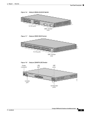
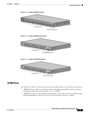
Front-Panel Description Figure 1-2 Catalyst 2950-24 Switch SYST RPS STAT UTIL DUPLX SPEED MODE 1 2 3 4x 5x 6x 7x 8x 9x 10x 11x 10Base-T / 100Base-TX 12x 13x 14x 15x 16x 17x 18x 19x 20x 21x 22x 23x Catalyst 2950 SERIES 24x 10/100 ports Figure 1-3 Catalyst 2950C-24 Switch SYST RPS STAT UTIL DUPLX ... RPS STAT UTIL DUPLX SPEED MODE 1 1X 23 45 67 8 9 10 11 12 11X 2X 12X 10/100 ports 1 Catalyst 2950 SERIES 2 GBIC module slots Figure 1-5 Catalyst 2950G-24-EI Switch SYST RPS STAT UTIL DUPLX SPEED MODE 1 1X 23 45 67 8 9 10 11 12 11X 2X 12X 13 13X ...
Front-Panel Description Figure 1-2 Catalyst 2950-24 Switch SYST RPS STAT UTIL DUPLX SPEED MODE 1 2 3 4x 5x 6x 7x 8x 9x 10x 11x 10Base-T / 100Base-TX 12x 13x 14x 15x 16x 17x 18x 19x 20x 21x 22x 23x Catalyst 2950 SERIES 24x 10/100 ports Figure 1-3 Catalyst 2950C-24 Switch SYST RPS STAT UTIL DUPLX ... RPS STAT UTIL DUPLX SPEED MODE 1 1X 23 45 67 8 9 10 11 12 11X 2X 12X 10/100 ports 1 Catalyst 2950 SERIES 2 GBIC module slots Figure 1-5 Catalyst 2950G-24-EI Switch SYST RPS STAT UTIL DUPLX SPEED MODE 1 1X 23 45 67 8 9 10 11 12 11X 2X 12X 13 13X ...
Hardware Installation Guide
Page 25
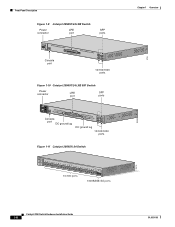
... 67 8 9 10 11 12 11X 2X 12X 13X 13 14 15 16 17 18 19 20 21 22 23 24 23X 14X 24X 10/100 ports 1 Catalyst 2950 SERIES 2 GBIC module slots Figure 1-7 Catalyst 2950G-48-EI Switch SYST RPS STAT UTIL DUPLX SPEED MODE 1 1X 2X 23 45 67 8 9 10 11 12 13 14 15... 21 22 23 24 25 26 27 28 29 30 31 32 16X 18X 33 31X 33X 34 35 36 37 38 39 40 41 42 43 44 45 46 47 48 47X 32X 34X 48X 10/100 ports Catalyst 2950 SERIES 1 2 GBIC module slots Figure 1-8 Catalyst 2950ST-8 LRE Switch Power LRE connector port SFP ports 110.00A...
... 67 8 9 10 11 12 11X 2X 12X 13X 13 14 15 16 17 18 19 20 21 22 23 24 23X 14X 24X 10/100 ports 1 Catalyst 2950 SERIES 2 GBIC module slots Figure 1-7 Catalyst 2950G-48-EI Switch SYST RPS STAT UTIL DUPLX SPEED MODE 1 1X 2X 23 45 67 8 9 10 11 12 13 14 15... 21 22 23 24 25 26 27 28 29 30 31 32 16X 18X 33 31X 33X 34 35 36 37 38 39 40 41 42 43 44 45 46 47 48 47X 32X 34X 48X 10/100 ports Catalyst 2950 SERIES 1 2 GBIC module slots Figure 1-8 Catalyst 2950ST-8 LRE Switch Power LRE connector port SFP ports 110.00A...
Hardware Installation Guide
Page 26
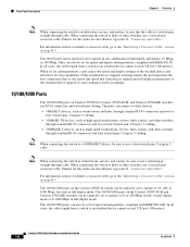
... Description Figure 1-9 Catalyst 2950ST-24 LRE Switch Power LRE connector port SFP ports 110.00A-1/02R.75A/TA2I0N500G--26400HVZ~ MODE SYST RPS STAT SPEED CONSOLE 1 2 3 4 5 6 7 8 9 10 11 12 Console port 13 14 15 16 17 18 19 20 21 22 23 24 Catalyst 2950 SERIES LRE 1 2 1 2 10/100/1000 ports Figure 1-10 Catalyst 2950ST-24 LRE 997 Switch Power connector LRE port SFP ports - ++ A INPCUUTR...
... Description Figure 1-9 Catalyst 2950ST-24 LRE Switch Power LRE connector port SFP ports 110.00A-1/02R.75A/TA2I0N500G--26400HVZ~ MODE SYST RPS STAT SPEED CONSOLE 1 2 3 4 5 6 7 8 9 10 11 12 Console port 13 14 15 16 17 18 19 20 21 22 23 24 Catalyst 2950 SERIES LRE 1 2 1 2 10/100/1000 ports Figure 1-10 Catalyst 2950ST-24 LRE 997 Switch Power connector LRE port SFP ports - ++ A INPCUUTR...
Hardware Installation Guide
Page 27
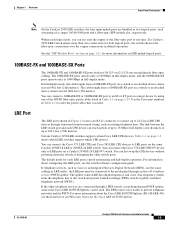
... as high-speed workstations, servers, hubs, routers, and other switches, through standard RJ-45 connectors and two twisted-pair cabling. The ports can use RJ-45 connectors and twisted-pair cabling. OL-6156-01 Catalyst 2950 Switch Hardware Installation Guide 1-7 Chapter 1 Overview Figure 1-12 Catalyst 2950T-24 Switch Front-Panel Description 47337 SYST RPS STAT UTIL DUPLX SPEED...
... as high-speed workstations, servers, hubs, routers, and other switches, through standard RJ-45 connectors and two twisted-pair cabling. The ports can use RJ-45 connectors and twisted-pair cabling. OL-6156-01 Catalyst 2950 Switch Hardware Installation Guide 1-7 Chapter 1 Overview Figure 1-12 Catalyst 2950T-24 Switch Front-Panel Description 47337 SYST RPS STAT UTIL DUPLX SPEED...
Hardware Installation Guide
Page 28
... combination of the attached device and advertises its own capabilities. The 10/100/1000 ports on Catalyst 2950T-24, Catalyst 2950T-48-SI, and Catalyst 2950 LRE switches use RJ-45 connectors and twisted-pair cabling. If the attached device supports autonegotiation, the port negotiates the best connection (that both devices support and full-duplex transmission, if the...
... combination of the attached device and advertises its own capabilities. The 10/100/1000 ports on Catalyst 2950T-24, Catalyst 2950T-48-SI, and Catalyst 2950 LRE switches use RJ-45 connectors and twisted-pair cabling. If the attached device supports autonegotiation, the port negotiates the best connection (that both devices support and full-duplex transmission, if the...
Hardware Installation Guide
Page 29
...-optic cabling. You can connect the Cisco 576 LRE CPE 997 device only to LRE ports on a Catalyst 2950ST-24 LRE 997 switch. You can connect the Cisco 575 LRE CPE and Cisco 585 LRE CPE devices to LRE ports on a switch to an attached device cannot exceed 1804...port on the same Catalyst 2950ST-8 LRE or 2950ST-24 LRE switch. OL-6156-01 Catalyst 2950 Switch Hardware Installation Guide 1-9 In full-duplex mode, the cable length from a 100BASE-FX port on LRE uplink logical ports. 100BASE-FX and 1000BASE-SX Ports The 100BASE-FX and 1000BASE-SX ports both logical ports, the switch...
...-optic cabling. You can connect the Cisco 576 LRE CPE 997 device only to LRE ports on a Catalyst 2950ST-24 LRE 997 switch. You can connect the Cisco 575 LRE CPE and Cisco 585 LRE CPE devices to LRE ports on a switch to an attached device cannot exceed 1804...port on the same Catalyst 2950ST-8 LRE or 2950ST-24 LRE switch. OL-6156-01 Catalyst 2950 Switch Hardware Installation Guide 1-9 In full-duplex mode, the cable length from a 100BASE-FX port on LRE uplink logical ports. 100BASE-FX and 1000BASE-SX Ports The 100BASE-FX and 1000BASE-SX ports both logical ports, the switch...

Hardware Installation Guide
Page 104
...same color. H5578 Figure B-11 Two Twisted-Pair Crossover Cable Schematic for 10/100 Ports Switch 3 TD+ 6 TD- Router or PC 3 RD+ 6 RD- 1 RD+ 2 RD- 1 TD+ 2 TD- H5579 Catalyst 2950 Switch Hardware Installation Guide B-6 OL-6156-01 Figure B-10 Two Twisted-Pair Straight-Through ...Cable Schematic for 10/100 Ports Switch 3 TD+ 6 TD- Pin 1 Appendix B Connectors and Cables Pin 8 H10632 Cable and Adapter Specifications These sections describe the cables and adapters used with Catalyst 2950 switches. • Two Twisted-Pair Cable Pinouts, page B-6 &#...
...same color. H5578 Figure B-11 Two Twisted-Pair Crossover Cable Schematic for 10/100 Ports Switch 3 TD+ 6 TD- Router or PC 3 RD+ 6 RD- 1 RD+ 2 RD- 1 TD+ 2 TD- H5579 Catalyst 2950 Switch Hardware Installation Guide B-6 OL-6156-01 Figure B-10 Two Twisted-Pair Straight-Through ...Cable Schematic for 10/100 Ports Switch 3 TD+ 6 TD- Pin 1 Appendix B Connectors and Cables Pin 8 H10632 Cable and Adapter Specifications These sections describe the cables and adapters used with Catalyst 2950 switches. • Two Twisted-Pair Cable Pinouts, page B-6 &#...

Hardware Installation Guide
Page 105
...-Pair Straight-Through Cable Schematic for 10/100 ports. Switch 1 RD+ 2 RD3 TD+ 6 TD- 4 NC 5 NC 7 NC 8 NC 4 NC 5 NC 7 NC 8 NC 65273 OL-6156-01 Catalyst 2950 Switch Hardware Installation Guide B-7 Appendix B Connectors and Cables Cable and Adapter Specifications Four Twisted-Pair Cable Pinouts for 10/100 Ports Figure B-12 and Figure B-13 show the...
...-Pair Straight-Through Cable Schematic for 10/100 ports. Switch 1 RD+ 2 RD3 TD+ 6 TD- 4 NC 5 NC 7 NC 8 NC 4 NC 5 NC 7 NC 8 NC 65273 OL-6156-01 Catalyst 2950 Switch Hardware Installation Guide B-7 Appendix B Connectors and Cables Cable and Adapter Specifications Four Twisted-Pair Cable Pinouts for 10/100 Ports Figure B-12 and Figure B-13 show the...

Hardware Installation Guide
Page 106
... the RJ-21 cable pinouts on Catalyst 2950T-24 switches, Catalyst 2950 LRE switches, and 1000BASE-T GBIC module ports. Router or PC 1 TP1+ 2 TP13 TPO+ 6 TPO- 4 TP2+ 5 TP27 TP3+ 8 TP3- 4 TP3+ 5 TP37 TP2+ 8 TP2- 65272 Figure B-15 Four Twisted-Pair Crossover Cable Schematics for 10/100/1000 and 1000BASE-T GBIC Module Ports Switch 1 TPO+ 2 TPO3 TP1+ 6 TP1- Figure B-14...
... the RJ-21 cable pinouts on Catalyst 2950T-24 switches, Catalyst 2950 LRE switches, and 1000BASE-T GBIC module ports. Router or PC 1 TP1+ 2 TP13 TPO+ 6 TPO- 4 TP2+ 5 TP27 TP3+ 8 TP3- 4 TP3+ 5 TP37 TP2+ 8 TP2- 65272 Figure B-15 Four Twisted-Pair Crossover Cable Schematics for 10/100/1000 and 1000BASE-T GBIC Module Ports Switch 1 TPO+ 2 TPO3 TP1+ 6 TP1- Figure B-14...

Configuration Guide
Page 92
... on page 10-6. "Configuring CoS Maps" section on page 13-13. Port > Protected Port 4-10 Catalyst 2950 Desktop Switch Software Configuration Guide 78-11380-03 "Configuring a QoS Policy" section on page 13-21. - Port > Switch Port Analyzer (SPAN) - - Reports "Configuring SPAN" section on page 6-15. Documentation set for Cisco IOS Release 12.1 on - "Managing the MAC Address Tables" section...
... on page 10-6. "Configuring CoS Maps" section on page 13-13. Port > Protected Port 4-10 Catalyst 2950 Desktop Switch Software Configuration Guide 78-11380-03 "Configuring a QoS Policy" section on page 13-21. - Port > Switch Port Analyzer (SPAN) - - Reports "Configuring SPAN" section on page 6-15. Documentation set for Cisco IOS Release 12.1 on - "Managing the MAC Address Tables" section...

Configuration Guide
Page 205
....20.26.155 Switch 7 172.20.26.156 End station 2 Switch 8 Dynamic-access port Switch 9 Secondary VMPS Server 3 Switch 10 172.20.26.157 Client 172.20.26.158 Trunk port 172.20.26.159 30769 Ethernet segment (Trunk link) How the VMPS Works TFTP server Router 172.20.22.7 78-11380-03 Catalyst 2950 Desktop Switch Software Configuration...
....20.26.155 Switch 7 172.20.26.156 End station 2 Switch 8 Dynamic-access port Switch 9 Secondary VMPS Server 3 Switch 10 172.20.26.157 Client 172.20.26.158 Trunk port 172.20.26.159 30769 Ethernet segment (Trunk link) How the VMPS Works TFTP server Router 172.20.22.7 78-11380-03 Catalyst 2950 Desktop Switch Software Configuration...

Configuration Guide
Page 219
... or 1000 Mbps Link C (Alternate redundant link) 100 or 1000 Mbps Stack-root port Alternate stackroot port Alternate stackroot port Switch A Stack port Switch B Stack port Switch C Stack port 49067 Multidrop backbone (GigaStack GBIC connections) CSUF implements the Stack Membership Discovery Protocol and ...ports to communicate with each other and to connect to form a multidrop backbone, which communicates control and data traffic across the stack of discovery hello packets. Link A, the root link, is elected as the path to stack members. 78-11380-03 Catalyst 2950 Desktop Switch...
... or 1000 Mbps Link C (Alternate redundant link) 100 or 1000 Mbps Stack-root port Alternate stackroot port Alternate stackroot port Switch A Stack port Switch B Stack port Switch C Stack port 49067 Multidrop backbone (GigaStack GBIC connections) CSUF implements the Stack Membership Discovery Protocol and ...ports to communicate with each other and to connect to form a multidrop backbone, which communicates control and data traffic across the stack of discovery hello packets. Link A, the root link, is elected as the path to stack members. 78-11380-03 Catalyst 2950 Desktop Switch...

Configuration Guide
Page 224
... a shared-medium topology as shown in a Shared-Medium Topology Switch A (Root) Switch C Blocked port Switch B (Designated bridge) Added switch 44965 9-18 Catalyst 2950 Desktop Switch Software Configuration Guide 78-11380-03 Figure 9-12 Adding a Switch in Figure 9-12, BackboneFast is set. The new switch begins sending inferior BPDUs that Switch B is the root switch. Understanding Advanced STP Features Chapter 9 Configuring STP switchover...
... a shared-medium topology as shown in a Shared-Medium Topology Switch A (Root) Switch C Blocked port Switch B (Designated bridge) Added switch 44965 9-18 Catalyst 2950 Desktop Switch Software Configuration Guide 78-11380-03 Figure 9-12 Adding a Switch in Figure 9-12, BackboneFast is set. The new switch begins sending inferior BPDUs that Switch B is the root switch. Understanding Advanced STP Features Chapter 9 Configuring STP switchover...


