

Hardware Installation Guide
Page 3
... Overview 1-1 Setting up the Switch 1-1 Features 1-1 Front-Panel Description 1-3 10/100 Ports 1-7 10/100/1000 Ports 1-8 100BASE-FX and 1000BASE-SX Ports 1-9 LRE Port 1-9 GBIC Module Ports 1-10 SFP Module Slots 1-11 SFP Modules 1-11 LEDs 1-13 System LED 1-16 RPS LED 1-16 Port Mode and Port Status LEDs 1-16 CONTENTS OL-6156-01 Catalyst 2950 Switch Hardware Installation Guide iii
... Overview 1-1 Setting up the Switch 1-1 Features 1-1 Front-Panel Description 1-3 10/100 Ports 1-7 10/100/1000 Ports 1-8 100BASE-FX and 1000BASE-SX Ports 1-9 LRE Port 1-9 GBIC Module Ports 1-10 SFP Module Slots 1-11 SFP Modules 1-11 LEDs 1-13 System LED 1-16 RPS LED 1-16 Port Mode and Port Status LEDs 1-16 CONTENTS OL-6156-01 Catalyst 2950 Switch Hardware Installation Guide iii
Hardware Installation Guide
Page 4
... Cisco RPS Connector 1-23 Console Port 1-24 Management Options 1-24 Installation 2-1 Preparing for Installation 2-1 Warnings 2-1 Installation Guidelines 2-4 Verifying Package Contents 2-5 Verifying Switch Operation 2-6 Installing the Switch 2-7 Installing the Switch in a Rack 2-7 Attaching the Brackets to the Switch 2-8 Mounting the Switch in...Switch on a Table, Shelf, or Desk 2-17 Installing the Switch on a Wall 2-17 Attaching the Brackets to the Switch 2-17 Attaching the RPS Connector Cover 2-18 Mounting the Switch to a Wall 2-18 Installing the Optional AC Ground Kit for Catalyst 2950 Switches...
... Cisco RPS Connector 1-23 Console Port 1-24 Management Options 1-24 Installation 2-1 Preparing for Installation 2-1 Warnings 2-1 Installation Guidelines 2-4 Verifying Package Contents 2-5 Verifying Switch Operation 2-6 Installing the Switch 2-7 Installing the Switch in a Rack 2-7 Attaching the Brackets to the Switch 2-8 Mounting the Switch in...Switch on a Table, Shelf, or Desk 2-17 Installing the Switch on a Wall 2-17 Attaching the Brackets to the Switch 2-17 Attaching the RPS Connector Cover 2-18 Mounting the Switch to a Wall 2-18 Installing the Optional AC Ground Kit for Catalyst 2950 Switches...

Hardware Installation Guide
Page 5
... Ports B-4 1000BASE-X GBIC Module Ports B-4 1000BASE-T GBIC Module Ports B-4 GigaStack GBIC Module Ports B-4 SFP Module Ports B-5 Console Port B-5 Identifying a Crossover Cable B-5 Cable and Adapter Specifications B-6 Two Twisted-Pair Cable Pinouts B-6 Four Twisted-Pair Cable Pinouts for 10/100 Ports B-7 Four Twisted-Pair Cable Pinouts for 1000BASE-T Ports B-8 RJ-21 Cable Pinouts B-8 Adapter Pinouts B-10 Contents OL-6156-01 Catalyst 2950 Switch...
... Ports B-4 1000BASE-X GBIC Module Ports B-4 1000BASE-T GBIC Module Ports B-4 GigaStack GBIC Module Ports B-4 SFP Module Ports B-5 Console Port B-5 Identifying a Crossover Cable B-5 Cable and Adapter Specifications B-6 Two Twisted-Pair Cable Pinouts B-6 Four Twisted-Pair Cable Pinouts for 10/100 Ports B-7 Four Twisted-Pair Cable Pinouts for 1000BASE-T Ports B-8 RJ-21 Cable Pinouts B-8 Adapter Pinouts B-10 Contents OL-6156-01 Catalyst 2950 Switch...

Hardware Installation Guide
Page 6
... the CLI D-1 Accessing the CLI Through Express Setup D-1 Accessing the CLI Through the Console Port D-2 Taking Out What You Need D-3 Connecting to the Console Port D-3 Starting the Terminal-Emulation Software D-4 Connecting to a Power Source D-5 Entering the Initial Configuration Information D-5 IP Settings D-5 Completing the Setup Program D-6 Catalyst 2950 Switch Hardware Installation Guide vi OL-6156-01
... the CLI D-1 Accessing the CLI Through Express Setup D-1 Accessing the CLI Through the Console Port D-2 Taking Out What You Need D-3 Connecting to the Console Port D-3 Starting the Terminal-Emulation Software D-4 Connecting to a Power Source D-5 Entering the Initial Configuration Information D-5 IP Settings D-5 Completing the Setup Program D-6 Catalyst 2950 Switch Hardware Installation Guide vi OL-6156-01
Hardware Installation Guide
Page 21
..., power connection procedures for examples that you might deploy the switches in the getting started guide are the switch features: • Hardware - Catalyst 2950-24 switch-24 10/100 Ethernet ports - See the switch software configuration guide for both AC- Also covered in your network. Catalyst 2950-12 switch-12 10/100 Ethernet ports - Overview CH A P T E R 1 This chapter provides information about these topics...
..., power connection procedures for examples that you might deploy the switches in the getting started guide are the switch features: • Hardware - Catalyst 2950-24 switch-24 10/100 Ethernet ports - See the switch software configuration guide for both AC- Also covered in your network. Catalyst 2950-12 switch-12 10/100 Ethernet ports - Overview CH A P T E R 1 This chapter provides information about these topics...

Hardware Installation Guide
Page 22
... - Catalyst 2950T-24 switch-24 10/100 Ethernet ports and 2 10/100/1000 Ethernet ports - For 10/100/1000 ports on the Catalyst 2950T-48-SI and 2950 LRE switches, autonegotiates the speed and duplex setting when operating at one time.) Note See the Catalyst 2950 LRE switch release notes for the Catalyst 2950 LRE switches. - When the switch is running at one time.) - Catalyst 2950ST-24 LRE 997 switch-24...
... - Catalyst 2950T-24 switch-24 10/100 Ethernet ports and 2 10/100/1000 Ethernet ports - For 10/100/1000 ports on the Catalyst 2950T-48-SI and 2950 LRE switches, autonegotiates the speed and duplex setting when operating at one time.) Note See the Catalyst 2950 LRE switch release notes for the Catalyst 2950 LRE switches. - When the switch is running at one time.) - Catalyst 2950ST-24 LRE 997 switch-24...

Hardware Installation Guide
Page 23
... Cisco 585 LRE Yes CPE Catalyst 2950ST-24 LRE Catalyst 2950ST-24 LRE 997 Yes No No Yes Yes No Front-Panel Description The switch front panel contains the ports, the LEDs, and the Mode button. On the Catalyst 2950ST-24 LRE 997 switch, the front panel contains a DC power connector (also referred to Figure 1-12 show the switches. Figure 1-1 Catalyst 2950-12 Switch...
... Cisco 585 LRE Yes CPE Catalyst 2950ST-24 LRE Catalyst 2950ST-24 LRE 997 Yes No No Yes Yes No Front-Panel Description The switch front panel contains the ports, the LEDs, and the Mode button. On the Catalyst 2950ST-24 LRE 997 switch, the front panel contains a DC power connector (also referred to Figure 1-12 show the switches. Figure 1-1 Catalyst 2950-12 Switch...

Hardware Installation Guide
Page 24
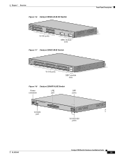
Front-Panel Description Figure 1-2 Catalyst 2950-24 Switch SYST RPS STAT UTIL DUPLX SPEED MODE 1 2 3 4x 5x 6x 7x 8x 9x 10x 11x 10Base-T / 100Base-TX 12x 13x 14x 15x 16x 17x 18x 19x 20x 21x 22x 23x Catalyst 2950 SERIES 24x 10/100 ports Figure 1-3 Catalyst 2950C-24 Switch SYST RPS STAT UTIL DUPLX ... RPS STAT UTIL DUPLX SPEED MODE 1 1X 23 45 67 8 9 10 11 12 11X 2X 12X 10/100 ports 1 Catalyst 2950 SERIES 2 GBIC module slots Figure 1-5 Catalyst 2950G-24-EI Switch SYST RPS STAT UTIL DUPLX SPEED MODE 1 1X 23 45 67 8 9 10 11 12 11X 2X 12X 13 13X ...
Front-Panel Description Figure 1-2 Catalyst 2950-24 Switch SYST RPS STAT UTIL DUPLX SPEED MODE 1 2 3 4x 5x 6x 7x 8x 9x 10x 11x 10Base-T / 100Base-TX 12x 13x 14x 15x 16x 17x 18x 19x 20x 21x 22x 23x Catalyst 2950 SERIES 24x 10/100 ports Figure 1-3 Catalyst 2950C-24 Switch SYST RPS STAT UTIL DUPLX ... RPS STAT UTIL DUPLX SPEED MODE 1 1X 23 45 67 8 9 10 11 12 11X 2X 12X 10/100 ports 1 Catalyst 2950 SERIES 2 GBIC module slots Figure 1-5 Catalyst 2950G-24-EI Switch SYST RPS STAT UTIL DUPLX SPEED MODE 1 1X 23 45 67 8 9 10 11 12 11X 2X 12X 13 13X ...
Hardware Installation Guide
Page 25
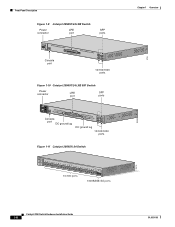
... 67 8 9 10 11 12 11X 2X 12X 13X 13 14 15 16 17 18 19 20 21 22 23 24 23X 14X 24X 10/100 ports 1 Catalyst 2950 SERIES 2 GBIC module slots Figure 1-7 Catalyst 2950G-48-EI Switch SYST RPS STAT UTIL DUPLX SPEED MODE 1 1X 2X 23 45 67 8 9 10 11 12 13 14 15... 21 22 23 24 25 26 27 28 29 30 31 32 16X 18X 33 31X 33X 34 35 36 37 38 39 40 41 42 43 44 45 46 47 48 47X 32X 34X 48X 10/100 ports Catalyst 2950 SERIES 1 2 GBIC module slots Figure 1-8 Catalyst 2950ST-8 LRE Switch Power LRE connector port SFP ports 110.00A...
... 67 8 9 10 11 12 11X 2X 12X 13X 13 14 15 16 17 18 19 20 21 22 23 24 23X 14X 24X 10/100 ports 1 Catalyst 2950 SERIES 2 GBIC module slots Figure 1-7 Catalyst 2950G-48-EI Switch SYST RPS STAT UTIL DUPLX SPEED MODE 1 1X 2X 23 45 67 8 9 10 11 12 13 14 15... 21 22 23 24 25 26 27 28 29 30 31 32 16X 18X 33 31X 33X 34 35 36 37 38 39 40 41 42 43 44 45 46 47 48 47X 32X 34X 48X 10/100 ports Catalyst 2950 SERIES 1 2 GBIC module slots Figure 1-8 Catalyst 2950ST-8 LRE Switch Power LRE connector port SFP ports 110.00A...
Hardware Installation Guide
Page 26
....75A/TA2I0N500G--26400HVZ~ MODE SYST RPS STAT SPEED CONSOLE 1 2 3 4 5 6 7 8 9 10 11 12 Console port 13 14 15 16 17 18 19 20 21 22 23 24 Catalyst 2950 SERIES LRE 1 2 1 2 10/100/1000 ports Figure 1-10 Catalyst 2950ST-24 LRE 997 Switch Power connector LRE port SFP ports - ++ A INPCUUTR:RE3N6T- SYST RPS STAT SPEED MODE CONSOLE 1 2 3 4 5 6 7 8 9 10 11 12 Console...
....75A/TA2I0N500G--26400HVZ~ MODE SYST RPS STAT SPEED CONSOLE 1 2 3 4 5 6 7 8 9 10 11 12 Console port 13 14 15 16 17 18 19 20 21 22 23 24 Catalyst 2950 SERIES LRE 1 2 1 2 10/100/1000 ports Figure 1-10 Catalyst 2950ST-24 LRE 997 Switch Power connector LRE port SFP ports - ++ A INPCUUTR:RE3N6T- SYST RPS STAT SPEED MODE CONSOLE 1 2 3 4 5 6 7 8 9 10 11 12 Console...
Hardware Installation Guide
Page 27
... 20 21 22 23 24 25 26 27 28 29 30 31 32 16X 18X 33 31X 33X 34 35 36 37 38 39 40 41 42 43 44 45 46 47 48 47X 32X 34X 48X 10/100 ports Catalyst 2950 SERIES 1 2 1000BASE-SX ports Figure 1-14 Catalyst 2950T-48-SI Switch 97626 SYST RPS STAT... UTIL DUPLX SPEED MODE 1 1X 2X 23 45 67 8 9 10 11 12 13 14 15 16 17 15X 17X 18 19 20 21 22 23 24 25 26 27 28 29 30...
... 20 21 22 23 24 25 26 27 28 29 30 31 32 16X 18X 33 31X 33X 34 35 36 37 38 39 40 41 42 43 44 45 46 47 48 47X 32X 34X 48X 10/100 ports Catalyst 2950 SERIES 1 2 1000BASE-SX ports Figure 1-14 Catalyst 2950T-48-SI Switch 97626 SYST RPS STAT... UTIL DUPLX SPEED MODE 1 1X 2X 23 45 67 8 9 10 11 12 13 14 15 16 17 15X 17X 18 19 20 21 22 23 24 25 26 27 28 29 30...
Hardware Installation Guide
Page 28
... transmission, if the attached device supports it) and configures itself accordingly. 10/100/1000 Ports The 10/100/1000 ports on Catalyst 2950T-24, Catalyst 2950T-48-SI, and Catalyst 2950 LRE switches use RJ-45 connectors and twisted-pair cabling. Pinouts for autonegotiation, a port senses the speed and duplex settings of half duplex, full duplex, 10 Mbps, or...
... transmission, if the attached device supports it) and configures itself accordingly. 10/100/1000 Ports The 10/100/1000 ports on Catalyst 2950T-24, Catalyst 2950T-48-SI, and Catalyst 2950 LRE switches use RJ-45 connectors and twisted-pair cabling. Pinouts for autonegotiation, a port senses the speed and duplex settings of half duplex, full duplex, 10 Mbps, or...
Hardware Installation Guide
Page 29
...Services Digital Network (ISDN), use 50/125- OL-6156-01 Catalyst 2950 Switch Hardware Installation Guide 1-9 LRE Port The LRE port (shown in Table 2-1 on page 2-29. You can be connected to 24 Cisco LRE CPE devices through structured or unstructured wiring, such as ...the other switch ports. You can connect the Cisco 575 LRE CPE and Cisco 585 LRE CPE devices to LRE ports on a Catalyst 2950ST-24 LRE 997 switch. Chapter 1 Overview Front-Panel Description Note On the Catalyst 2950 LRE switches, the four input uplink ports are connected through a PBX switch, a non...
...Services Digital Network (ISDN), use 50/125- OL-6156-01 Catalyst 2950 Switch Hardware Installation Guide 1-9 LRE Port The LRE port (shown in Table 2-1 on page 2-29. You can be connected to 24 Cisco LRE CPE devices through structured or unstructured wiring, such as ...the other switch ports. You can connect the Cisco 575 LRE CPE and Cisco 585 LRE CPE devices to LRE ports on a Catalyst 2950ST-24 LRE 997 switch. Chapter 1 Overview Front-Panel Description Note On the Catalyst 2950 LRE switches, the four input uplink ports are connected through a PBX switch, a non...

Hardware Installation Guide
Page 30
... the Catalyst 2950 LRE switches and Cisco LRE CPE, see the "Limitations and Restrictions with a Cisco-approved module. For more information about the Cisco LRE CPE devices, see your Cisco sales representative. When a GBIC module is not needed, and the switch can connect directly to nine supported switches. Front... name and ID, a unique security code, and cyclic redundancy check (CRC). GBIC Module Ports The GBIC module slots support these GBIC modules, see the Cisco LRE CPE Hardware Installation Guide. For more information about these modules: • 1000BASE-SX GBIC...
... the Catalyst 2950 LRE switches and Cisco LRE CPE, see the "Limitations and Restrictions with a Cisco-approved module. For more information about the Cisco LRE CPE devices, see your Cisco sales representative. When a GBIC module is not needed, and the switch can connect directly to nine supported switches. Front... name and ID, a unique security code, and cyclic redundancy check (CRC). GBIC Module Ports The GBIC module slots support these GBIC modules, see the Cisco LRE CPE Hardware Installation Guide. For more information about these modules: • 1000BASE-SX GBIC...

Hardware Installation Guide
Page 31
...the cable must not exceed the stipulated cable length. When determining where to place the switch, be connecting to 1550 nanometers (nm). The Catalyst 2950 LRE switch has four physical input ports that scenario, whichever media type establishes a link first has precedence over the other. For...optic SFP module connections. Within each port, you connect to both, in the Catalyst 2950 LRE switch release notes. For example, you can configure the Catalyst 2950 LRE switch so that the SFP module port does not take precedence over the 10/100/1000 port. Using this example, a valid ...
...the cable must not exceed the stipulated cable length. When determining where to place the switch, be connecting to 1550 nanometers (nm). The Catalyst 2950 LRE switch has four physical input ports that scenario, whichever media type establishes a link first has precedence over the other. For...optic SFP module connections. Within each port, you connect to both, in the Catalyst 2950 LRE switch release notes. For example, you can configure the Catalyst 2950 LRE switch so that the SFP module port does not take precedence over the 10/100/1000 port. Using this example, a valid ...

Hardware Installation Guide
Page 32
... the sending and receiving ends of splices, and the connectors. Front-Panel Description Chapter 1 Overview Table 1-2 Fiber-Optic SFP Module Port Cabling Specifications SFP Module Wavelength (nanometers) Fiber Type Core Size (micron) Modal Bandwidth (MHz/km) Cable Distance 1000BASE-SX 850 ...optical attenuator between the SFP module and the MMF cable on the Catalyst 2950 LRE switch. Using an ordinary patch cord with a Cisco-approved module. Note When using a non-Cisco approved SFP module, remove the module from the switch, and replace it with MMF, 1000BASE-LX/LH SFP modules,...
... the sending and receiving ends of splices, and the connectors. Front-Panel Description Chapter 1 Overview Table 1-2 Fiber-Optic SFP Module Port Cabling Specifications SFP Module Wavelength (nanometers) Fiber Type Core Size (micron) Modal Bandwidth (MHz/km) Cable Distance 1000BASE-SX 850 ...optical attenuator between the SFP module and the MMF cable on the Catalyst 2950 LRE switch. Using an ordinary patch cord with a Cisco-approved module. Note When using a non-Cisco approved SFP module, remove the module from the switch, and replace it with MMF, 1000BASE-LX/LH SFP modules,...

Hardware Installation Guide
Page 33
... the Mode button that you use the command-line interface (CLI) to configure and to monitor switch activity and performance. Figure 1-15 LEDs on Catalyst 2950-12, 2950-24, 2950C-24, 2950SX-24, and 2950T-24 Switches RPS LED Port status LEDs System LED Port mode LEDs SYST RPS STAT UTIL DUPLX SPEED MODE Mode button 1x 2x 3x 4x 5x...
... the Mode button that you use the command-line interface (CLI) to configure and to monitor switch activity and performance. Figure 1-15 LEDs on Catalyst 2950-12, 2950-24, 2950C-24, 2950SX-24, and 2950T-24 Switches RPS LED Port status LEDs System LED Port mode LEDs SYST RPS STAT UTIL DUPLX SPEED MODE Mode button 1x 2x 3x 4x 5x...
Hardware Installation Guide
Page 34
... Figure 1-16 LEDs on Catalyst 2950G-12-EI, 2950G-24-EI, and 2950G-24-EI-DC Switches RPS LED Port status LEDs 65395 System LED Port mode LEDs SYST RPS STAT UTIL DUPLX SPEED MODE 1 1X 23 45 67 8 9 10 11 12 11X 2X 12X Mode button Figure 1-17 LEDs on Catalyst 2950G-48-EI, 2950SX-48...-SI, and 2950T-48-SI Switches Port status LEDs System LED RPS LED Port mode LEDs SYST RPS STAT UTIL DUPLX SPEED MODE 1 1X 23 45 67 89 10 11 12 13 14 15 16 15X 2X 16X Mode button 65508 1-14 Catalyst 2950 Switch Hardware Installation Guide...
... Figure 1-16 LEDs on Catalyst 2950G-12-EI, 2950G-24-EI, and 2950G-24-EI-DC Switches RPS LED Port status LEDs 65395 System LED Port mode LEDs SYST RPS STAT UTIL DUPLX SPEED MODE 1 1X 23 45 67 8 9 10 11 12 11X 2X 12X Mode button Figure 1-17 LEDs on Catalyst 2950G-48-EI, 2950SX-48...-SI, and 2950T-48-SI Switches Port status LEDs System LED RPS LED Port mode LEDs SYST RPS STAT UTIL DUPLX SPEED MODE 1 1X 23 45 67 89 10 11 12 13 14 15 16 15X 2X 16X Mode button 65508 1-14 Catalyst 2950 Switch Hardware Installation Guide...

Hardware Installation Guide
Page 35
...Catalyst 2950ST-8 LRE and 2950ST-24 LRE Switches System LED Redundant power system LED Port status LEDs 81187 110.00A-1/02R.75A/TA2I0N500G--26400HVZ~ MODE SYST RPS STAT SPEED CONSOLE 1 2 3 4 5 6 7 8 Mode button Speed LED STAT LED Figure 1-19 LEDs on Catalyst 2950ST-24 LRE 997 Switches... System LED Redundant power system LED Port status LEDs -- ++ A INPCUUTR:RE3N6T- B 72 V :2-1 A SYST RPS STAT SPEED MODE CONSOLE STAT LED Speed Mode...
...Catalyst 2950ST-8 LRE and 2950ST-24 LRE Switches System LED Redundant power system LED Port status LEDs 81187 110.00A-1/02R.75A/TA2I0N500G--26400HVZ~ MODE SYST RPS STAT SPEED CONSOLE 1 2 3 4 5 6 7 8 Mode button Speed LED STAT LED Figure 1-19 LEDs on Catalyst 2950ST-24 LRE 997 Switches... System LED Redundant power system LED Port status LEDs -- ++ A INPCUUTR:RE3N6T- B 72 V :2-1 A SYST RPS STAT SPEED MODE CONSOLE STAT LED Speed Mode...

Hardware Installation Guide
Page 36
... to enable the highlighted mode. For information about the switch and the individual ports. System is receiving power and functioning properly. For more information about the Cisco RPS 675, see the Cisco RPS 300 Redundant Power System Hardware Installation Guide. RPS ...LED The RPS LED shows the RPS status. Port Mode and Port Status LEDs To select or change the port mode, press the Mode button (see Table 1-5) determine the type of information displayed. 1-16 Catalyst 2950 Switch...
... to enable the highlighted mode. For information about the switch and the individual ports. System is receiving power and functioning properly. For more information about the Cisco RPS 675, see the Cisco RPS 300 Redundant Power System Hardware Installation Guide. RPS ...LED The RPS LED shows the RPS status. Port Mode and Port Status LEDs To select or change the port mode, press the Mode button (see Table 1-5) determine the type of information displayed. 1-16 Catalyst 2950 Switch...


