

Hardware Installation Guide
Page 3
... Overview 1-1 Setting up the Switch 1-1 Features 1-1 Front-Panel Description 1-3 10/100 Ports 1-7 10/100/1000 Ports 1-8 100BASE-FX and 1000BASE-SX Ports 1-9 LRE Port 1-9 GBIC Module Ports 1-10 SFP Module Slots 1-11 SFP Modules 1-11 LEDs 1-13 System LED 1-16 RPS LED 1-16 Port Mode and Port Status LEDs 1-16 CONTENTS OL-6156-01 Catalyst 2950 Switch Hardware Installation Guide iii
... Overview 1-1 Setting up the Switch 1-1 Features 1-1 Front-Panel Description 1-3 10/100 Ports 1-7 10/100/1000 Ports 1-8 100BASE-FX and 1000BASE-SX Ports 1-9 LRE Port 1-9 GBIC Module Ports 1-10 SFP Module Slots 1-11 SFP Modules 1-11 LEDs 1-13 System LED 1-16 RPS LED 1-16 Port Mode and Port Status LEDs 1-16 CONTENTS OL-6156-01 Catalyst 2950 Switch Hardware Installation Guide iii
Hardware Installation Guide
Page 4
... Cisco RPS Connector 1-23 Console Port 1-24 Management Options 1-24 Installation 2-1 Preparing for Installation 2-1 Warnings 2-1 Installation Guidelines 2-4 Verifying Package Contents 2-5 Verifying Switch Operation 2-6 Installing the Switch 2-7 Installing the Switch in a Rack 2-7 Attaching the Brackets to the Switch 2-8 Mounting the Switch in...Switch on a Table, Shelf, or Desk 2-17 Installing the Switch on a Wall 2-17 Attaching the Brackets to the Switch 2-17 Attaching the RPS Connector Cover 2-18 Mounting the Switch to a Wall 2-18 Installing the Optional AC Ground Kit for Catalyst 2950 Switches...
... Cisco RPS Connector 1-23 Console Port 1-24 Management Options 1-24 Installation 2-1 Preparing for Installation 2-1 Warnings 2-1 Installation Guidelines 2-4 Verifying Package Contents 2-5 Verifying Switch Operation 2-6 Installing the Switch 2-7 Installing the Switch in a Rack 2-7 Attaching the Brackets to the Switch 2-8 Mounting the Switch in...Switch on a Table, Shelf, or Desk 2-17 Installing the Switch on a Wall 2-17 Attaching the Brackets to the Switch 2-17 Attaching the RPS Connector Cover 2-18 Mounting the Switch to a Wall 2-18 Installing the Optional AC Ground Kit for Catalyst 2950 Switches...

Hardware Installation Guide
Page 5
... Ports B-4 1000BASE-X GBIC Module Ports B-4 1000BASE-T GBIC Module Ports B-4 GigaStack GBIC Module Ports B-4 SFP Module Ports B-5 Console Port B-5 Identifying a Crossover Cable B-5 Cable and Adapter Specifications B-6 Two Twisted-Pair Cable Pinouts B-6 Four Twisted-Pair Cable Pinouts for 10/100 Ports B-7 Four Twisted-Pair Cable Pinouts for 1000BASE-T Ports B-8 RJ-21 Cable Pinouts B-8 Adapter Pinouts B-10 Contents OL-6156-01 Catalyst 2950 Switch...
... Ports B-4 1000BASE-X GBIC Module Ports B-4 1000BASE-T GBIC Module Ports B-4 GigaStack GBIC Module Ports B-4 SFP Module Ports B-5 Console Port B-5 Identifying a Crossover Cable B-5 Cable and Adapter Specifications B-6 Two Twisted-Pair Cable Pinouts B-6 Four Twisted-Pair Cable Pinouts for 10/100 Ports B-7 Four Twisted-Pair Cable Pinouts for 1000BASE-T Ports B-8 RJ-21 Cable Pinouts B-8 Adapter Pinouts B-10 Contents OL-6156-01 Catalyst 2950 Switch...

Hardware Installation Guide
Page 6
... the CLI D-1 Accessing the CLI Through Express Setup D-1 Accessing the CLI Through the Console Port D-2 Taking Out What You Need D-3 Connecting to the Console Port D-3 Starting the Terminal-Emulation Software D-4 Connecting to a Power Source D-5 Entering the Initial Configuration Information D-5 IP Settings D-5 Completing the Setup Program D-6 Catalyst 2950 Switch Hardware Installation Guide vi OL-6156-01
... the CLI D-1 Accessing the CLI Through Express Setup D-1 Accessing the CLI Through the Console Port D-2 Taking Out What You Need D-3 Connecting to the Console Port D-3 Starting the Terminal-Emulation Software D-4 Connecting to a Power Source D-5 Entering the Initial Configuration Information D-5 IP Settings D-5 Completing the Setup Program D-6 Catalyst 2950 Switch Hardware Installation Guide vi OL-6156-01
Hardware Installation Guide
Page 21
...: • Hardware - You can be deployed as servers, routers, and other switches and network devices. Catalyst 2950-24 switch-24 10/100 Ethernet ports - and DC-powered switches, and troubleshooting help. All models of Ethernet switches that show the Catalyst 2950 switches. Some switch models can use to create switch stacks by using Gigastack GBICs. Figure 1-1 through Figure 1-12 show how you can use...
...: • Hardware - You can be deployed as servers, routers, and other switches and network devices. Catalyst 2950-24 switch-24 10/100 Ethernet ports - and DC-powered switches, and troubleshooting help. All models of Ethernet switches that show the Catalyst 2950 switches. Some switch models can use to create switch stacks by using Gigastack GBICs. Figure 1-1 through Figure 1-12 show how you can use...

Hardware Installation Guide
Page 22
...-SX ports - Catalyst 2950G-24-EI-24 10/100 Ethernet ports and 2 GBIC module slots - Catalyst 2950ST-24 LRE 997 switch-24 LRE ports, 2 10/100/1000 Ethernet ports, and 2 SFP module slots with DC-input power - Catalyst 2950T-48-SI switch-48 10/100 Ethernet ports and 2 10/100/1000 Ethernet ports - For 10/100/1000 ports on the Catalyst 2950T-48-SI and 2950 LRE switches, autonegotiates...
...-SX ports - Catalyst 2950G-24-EI-24 10/100 Ethernet ports and 2 GBIC module slots - Catalyst 2950ST-24 LRE 997 switch-24 LRE ports, 2 10/100/1000 Ethernet ports, and 2 SFP module slots with DC-input power - Catalyst 2950T-48-SI switch-48 10/100 Ethernet ports and 2 10/100/1000 Ethernet ports - For 10/100/1000 ports on the Catalyst 2950T-48-SI and 2950 LRE switches, autonegotiates...

Hardware Installation Guide
Page 23
... than the Catalyst 2950ST-24 LRE 997 switch, the front panel of the Catalyst 2950 LRE switches also contain the console port and AC power connector. For more information on the console port on these switches, see the "Power Connectors" section on page 1-24. Connection for an optional Cisco RPS 675 that the CPE is supported by certain Catalyst 2950 LRE switches. For more...
... than the Catalyst 2950ST-24 LRE 997 switch, the front panel of the Catalyst 2950 LRE switches also contain the console port and AC power connector. For more information on the console port on these switches, see the "Power Connectors" section on page 1-24. Connection for an optional Cisco RPS 675 that the CPE is supported by certain Catalyst 2950 LRE switches. For more...

Hardware Installation Guide
Page 24
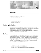
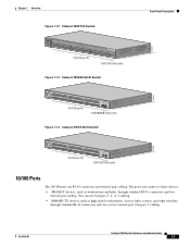
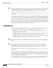
Front-Panel Description Figure 1-2 Catalyst 2950-24 Switch SYST RPS STAT UTIL DUPLX SPEED MODE 1 2 3 4x 5x 6x 7x 8x 9x 10x 11x 10Base-T / 100Base-TX 12x 13x 14x 15x 16x 17x 18x 19x 20x 21x 22x 23x Catalyst 2950 SERIES 24x 10/100 ports Figure 1-3 Catalyst 2950C-24 Switch SYST RPS STAT UTIL DUPLX ... RPS STAT UTIL DUPLX SPEED MODE 1 1X 23 45 67 8 9 10 11 12 11X 2X 12X 10/100 ports 1 Catalyst 2950 SERIES 2 GBIC module slots Figure 1-5 Catalyst 2950G-24-EI Switch SYST RPS STAT UTIL DUPLX SPEED MODE 1 1X 23 45 67 8 9 10 11 12 11X 2X 12X 13 13X ...
Front-Panel Description Figure 1-2 Catalyst 2950-24 Switch SYST RPS STAT UTIL DUPLX SPEED MODE 1 2 3 4x 5x 6x 7x 8x 9x 10x 11x 10Base-T / 100Base-TX 12x 13x 14x 15x 16x 17x 18x 19x 20x 21x 22x 23x Catalyst 2950 SERIES 24x 10/100 ports Figure 1-3 Catalyst 2950C-24 Switch SYST RPS STAT UTIL DUPLX ... RPS STAT UTIL DUPLX SPEED MODE 1 1X 23 45 67 8 9 10 11 12 11X 2X 12X 10/100 ports 1 Catalyst 2950 SERIES 2 GBIC module slots Figure 1-5 Catalyst 2950G-24-EI Switch SYST RPS STAT UTIL DUPLX SPEED MODE 1 1X 23 45 67 8 9 10 11 12 11X 2X 12X 13 13X ...
Hardware Installation Guide
Page 25
... 67 8 9 10 11 12 11X 2X 12X 13X 13 14 15 16 17 18 19 20 21 22 23 24 23X 14X 24X 10/100 ports 1 Catalyst 2950 SERIES 2 GBIC module slots Figure 1-7 Catalyst 2950G-48-EI Switch SYST RPS STAT UTIL DUPLX SPEED MODE 1 1X 2X 23 45 67 8 9 10 11 12 13 14 15... 21 22 23 24 25 26 27 28 29 30 31 32 16X 18X 33 31X 33X 34 35 36 37 38 39 40 41 42 43 44 45 46 47 48 47X 32X 34X 48X 10/100 ports Catalyst 2950 SERIES 1 2 GBIC module slots Figure 1-8 Catalyst 2950ST-8 LRE Switch Power LRE connector port SFP ports 110.00A...
... 67 8 9 10 11 12 11X 2X 12X 13X 13 14 15 16 17 18 19 20 21 22 23 24 23X 14X 24X 10/100 ports 1 Catalyst 2950 SERIES 2 GBIC module slots Figure 1-7 Catalyst 2950G-48-EI Switch SYST RPS STAT UTIL DUPLX SPEED MODE 1 1X 2X 23 45 67 8 9 10 11 12 13 14 15... 21 22 23 24 25 26 27 28 29 30 31 32 16X 18X 33 31X 33X 34 35 36 37 38 39 40 41 42 43 44 45 46 47 48 47X 32X 34X 48X 10/100 ports Catalyst 2950 SERIES 1 2 GBIC module slots Figure 1-8 Catalyst 2950ST-8 LRE Switch Power LRE connector port SFP ports 110.00A...
Hardware Installation Guide
Page 26
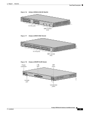
....75A/TA2I0N500G--26400HVZ~ MODE SYST RPS STAT SPEED CONSOLE 1 2 3 4 5 6 7 8 9 10 11 12 Console port 13 14 15 16 17 18 19 20 21 22 23 24 Catalyst 2950 SERIES LRE 1 2 1 2 10/100/1000 ports Figure 1-10 Catalyst 2950ST-24 LRE 997 Switch Power connector LRE port SFP ports - ++ A INPCUUTR:RE3N6T- B 72 V :2-1 A - SYST RPS STAT SPEED MODE CONSOLE 1 2 3 4 5 6 7 8 9 10 11 12...
....75A/TA2I0N500G--26400HVZ~ MODE SYST RPS STAT SPEED CONSOLE 1 2 3 4 5 6 7 8 9 10 11 12 Console port 13 14 15 16 17 18 19 20 21 22 23 24 Catalyst 2950 SERIES LRE 1 2 1 2 10/100/1000 ports Figure 1-10 Catalyst 2950ST-24 LRE 997 Switch Power connector LRE port SFP ports - ++ A INPCUUTR:RE3N6T- B 72 V :2-1 A - SYST RPS STAT SPEED MODE CONSOLE 1 2 3 4 5 6 7 8 9 10 11 12...
Hardware Installation Guide
Page 27
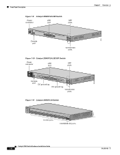
... 20 21 22 23 24 25 26 27 28 29 30 31 32 16X 18X 33 31X 33X 34 35 36 37 38 39 40 41 42 43 44 45 46 47 48 47X 32X 34X 48X 10/100 ports Catalyst 2950 SERIES 1 2 1000BASE-SX ports Figure 1-14 Catalyst 2950T-48-SI Switch 97626 SYST RPS STAT... UTIL DUPLX SPEED MODE 1 1X 2X 23 45 67 8 9 10 11 12 13 14 15 16 17 15X 17X 18 19 20 21 22 23 24 25 26 27 28 29 30...
... 20 21 22 23 24 25 26 27 28 29 30 31 32 16X 18X 33 31X 33X 34 35 36 37 38 39 40 41 42 43 44 45 46 47 48 47X 32X 34X 48X 10/100 ports Catalyst 2950 SERIES 1 2 1000BASE-SX ports Figure 1-14 Catalyst 2950T-48-SI Switch 97626 SYST RPS STAT... UTIL DUPLX SPEED MODE 1 1X 2X 23 45 67 8 9 10 11 12 13 14 15 16 17 15X 17X 18 19 20 21 22 23 24 25 26 27 28 29 30...
Hardware Installation Guide
Page 28
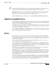
... devices support and full-duplex transmission, if the attached device supports it) and configures itself accordingly. 10/100/1000 Ports The 10/100/1000 ports on Catalyst 2950T-24, Catalyst 2950T-48-SI, and Catalyst 2950 LRE switches use RJ-45 connectors and twisted-pair cabling. They can also be set for speed and duplex autonegotiation, compliant with...
... devices support and full-duplex transmission, if the attached device supports it) and configures itself accordingly. 10/100/1000 Ports The 10/100/1000 ports on Catalyst 2950T-24, Catalyst 2950T-48-SI, and Catalyst 2950 LRE switches use RJ-45 connectors and twisted-pair cabling. They can also be set for speed and duplex autonegotiation, compliant with...
Hardware Installation Guide
Page 29
...-01 Catalyst 2950 Switch Hardware Installation Guide 1-9 If the other switch ports. If a Catalyst 2950 LRE switch senses more information about configuring the LRE ports, see the Installation and Warranty Notes for both use the same cabling as LRE traffic, the LRE port must be used. You can connect the Cisco 576 LRE CPE 997 device only to LRE ports on a Catalyst 2950ST-24...
...-01 Catalyst 2950 Switch Hardware Installation Guide 1-9 If the other switch ports. If a Catalyst 2950 LRE switch senses more information about configuring the LRE ports, see the Installation and Warranty Notes for both use the same cabling as LRE traffic, the LRE port must be used. You can connect the Cisco 576 LRE CPE 997 device only to LRE ports on a Catalyst 2950ST-24...

Hardware Installation Guide
Page 104
... H5578 Figure B-11 Two Twisted-Pair Crossover Cable Schematic for 10/100 Ports Switch 3 TD+ 6 TD- H5579 Catalyst 2950 Switch Hardware Installation Guide B-6 OL-6156-01 Figure B-10 Two Twisted-Pair Straight-Through Cable Schematic for 10/100 Ports Switch 3 TD+ 6 TD- Cable and Adapter Specifications Figure B-9 Identifying a...describe the cables and adapters used with Catalyst 2950 switches. • Two Twisted-Pair Cable Pinouts, page B-6 • Four Twisted-Pair Cable Pinouts for 10/100 Ports, page B-7 • Four Twisted-Pair Cable Pinouts for 1000BASE-T Ports, page B-8 • RJ-21 ...
... H5578 Figure B-11 Two Twisted-Pair Crossover Cable Schematic for 10/100 Ports Switch 3 TD+ 6 TD- H5579 Catalyst 2950 Switch Hardware Installation Guide B-6 OL-6156-01 Figure B-10 Two Twisted-Pair Straight-Through Cable Schematic for 10/100 Ports Switch 3 TD+ 6 TD- Cable and Adapter Specifications Figure B-9 Identifying a...describe the cables and adapters used with Catalyst 2950 switches. • Two Twisted-Pair Cable Pinouts, page B-6 • Four Twisted-Pair Cable Pinouts for 10/100 Ports, page B-7 • Four Twisted-Pair Cable Pinouts for 1000BASE-T Ports, page B-8 • RJ-21 ...

Hardware Installation Guide
Page 105
Figure B-12 Four Twisted-Pair Straight-Through Cable Schematic for 10/100 Ports Switch 1 RD+ 2 RD3 TD+ 6 TD- Switch 1 RD+ 2 RD3 TD+ 6 TD- 4 NC 5 NC 7 NC 8 NC 4 NC 5 NC 7 NC 8 NC 65273 OL-6156-01 Catalyst 2950 Switch Hardware Installation Guide B-7 Router or PC 1 TD+ 2 TD3 RD+ 6 RD- 4 NC 5 NC 7 ...NC 8 NC 4 NC 5 NC 7 NC 8 NC 65271 Figure B-13 Four Twisted-Pair Crossover Cable Schematic for 10/100 Ports Switch 1 RD+ 2 RD3 TD+ 6 TD- Appendix B...
Figure B-12 Four Twisted-Pair Straight-Through Cable Schematic for 10/100 Ports Switch 1 RD+ 2 RD3 TD+ 6 TD- Switch 1 RD+ 2 RD3 TD+ 6 TD- 4 NC 5 NC 7 NC 8 NC 4 NC 5 NC 7 NC 8 NC 65273 OL-6156-01 Catalyst 2950 Switch Hardware Installation Guide B-7 Router or PC 1 TD+ 2 TD3 RD+ 6 RD- 4 NC 5 NC 7 ...NC 8 NC 4 NC 5 NC 7 NC 8 NC 65271 Figure B-13 Four Twisted-Pair Crossover Cable Schematic for 10/100 Ports Switch 1 RD+ 2 RD3 TD+ 6 TD- Appendix B...

Hardware Installation Guide
Page 106
... Function Port 1 Tip Port 2 Tip Port 3 Tip Port 4 Tip Pin Pin Function 1 26 Port 1 Ring 2 27 Port 2 Ring 3 28 Port 3 Ring 4 29 Port 4 Ring Catalyst 2950 Switch Hardware Installation Guide B-8 OL-6156-01 Switch 1 TP0+ 2 TP03 TP1+ 6 TP1- 4 TP2+ 5 TP27 TP3+ 8 TP3- 4 TP2+ 5 TP27 TP3+ 8 TP3- 65274 RJ-21 Cable Pinouts Table B-1 lists the RJ-21 cable pinouts on Catalyst 2950T-24 switches, Catalyst 2950 LRE switches, and...
... Function Port 1 Tip Port 2 Tip Port 3 Tip Port 4 Tip Pin Pin Function 1 26 Port 1 Ring 2 27 Port 2 Ring 3 28 Port 3 Ring 4 29 Port 4 Ring Catalyst 2950 Switch Hardware Installation Guide B-8 OL-6156-01 Switch 1 TP0+ 2 TP03 TP1+ 6 TP1- 4 TP2+ 5 TP27 TP3+ 8 TP3- 4 TP2+ 5 TP27 TP3+ 8 TP3- 65274 RJ-21 Cable Pinouts Table B-1 lists the RJ-21 cable pinouts on Catalyst 2950T-24 switches, Catalyst 2950 LRE switches, and...

Configuration Guide
Page 92
.... Addresses "Adding Trap Managers" section on page 4-4. "Enabling Port Security" section on Cisco.com. Port > Protected Port 4-10 Catalyst 2950 Desktop Switch Software Configuration Guide 78-11380-03 Documentation set for Cisco IOS Release 12.1 on page 10-6. Documentation set for Cisco IOS Release 12.1 on - Port > Port Security "Configuring TACACS+" section on Cisco.com. page 6-20. Report > System Messages "Passwords" section...
.... Addresses "Adding Trap Managers" section on page 4-4. "Enabling Port Security" section on Cisco.com. Port > Protected Port 4-10 Catalyst 2950 Desktop Switch Software Configuration Guide 78-11380-03 Documentation set for Cisco IOS Release 12.1 on page 10-6. Documentation set for Cisco IOS Release 12.1 on - Port > Port Security "Configuring TACACS+" section on Cisco.com. page 6-20. Report > System Messages "Passwords" section...

Configuration Guide
Page 205
....20.26.155 Switch 7 172.20.26.156 End station 2 Switch 8 Dynamic-access port Switch 9 Secondary VMPS Server 3 Switch 10 172.20.26.157 Client 172.20.26.158 Trunk port 172.20.26.159 30769 Ethernet segment (Trunk link) How the VMPS Works TFTP server Router 172.20.22.7 78-11380-03 Catalyst 2950 Desktop Switch Software Configuration...
....20.26.155 Switch 7 172.20.26.156 End station 2 Switch 8 Dynamic-access port Switch 9 Secondary VMPS Server 3 Switch 10 172.20.26.157 Client 172.20.26.158 Trunk port 172.20.26.159 30769 Ethernet segment (Trunk link) How the VMPS Works TFTP server Router 172.20.22.7 78-11380-03 Catalyst 2950 Desktop Switch Software Configuration...

Configuration Guide
Page 219
...STP Features How CSUF Works CSUF ensures that one link in the STP forwarding state; the alternate stack-root ports on the stack port to stack members. 78-11380-03 Catalyst 2950 Desktop Switch Software Configuration Guide 9-13 Link A, the root link, is in the stack is elected as the path... to the spanning-tree root fails. If Switch A fails, if its link to the root. Figure 9-8 Cross-Stack UplinkFast Topology ...
...STP Features How CSUF Works CSUF ensures that one link in the STP forwarding state; the alternate stack-root ports on the stack port to stack members. 78-11380-03 Catalyst 2950 Desktop Switch Software Configuration Guide 9-13 Link A, the root link, is in the stack is elected as the path... to the spanning-tree root fails. If Switch A fails, if its link to the root. Figure 9-8 Cross-Stack UplinkFast Topology ...

Configuration Guide
Page 224
... BackboneFast Example After Indirect Link Failure Switch A (Root) Switch B L1 Link failure L2 L3 Switch C BackboneFast transitions port through listening and learning states to forwarding state. 44964 If a new switch is introduced into a shared-medium topology as shown in a Shared-Medium Topology Switch A (Root) Switch C Blocked port Switch B (Designated bridge) Added switch 44965 9-18 Catalyst 2950 Desktop Switch Software Configuration Guide 78-11380...
... BackboneFast Example After Indirect Link Failure Switch A (Root) Switch B L1 Link failure L2 L3 Switch C BackboneFast transitions port through listening and learning states to forwarding state. 44964 If a new switch is introduced into a shared-medium topology as shown in a Shared-Medium Topology Switch A (Root) Switch C Blocked port Switch B (Designated bridge) Added switch 44965 9-18 Catalyst 2950 Desktop Switch Software Configuration Guide 78-11380...


