

Hardware Installation Guide
Page 5
... Ports B-4 1000BASE-X GBIC Module Ports B-4 1000BASE-T GBIC Module Ports B-4 GigaStack GBIC Module Ports B-4 SFP Module Ports B-5 Console Port B-5 Identifying a Crossover Cable B-5 Cable and Adapter Specifications B-6 Two Twisted-Pair Cable Pinouts B-6 Four Twisted-Pair Cable Pinouts for 10/100 Ports B-7 Four Twisted-Pair Cable Pinouts for 1000BASE-T Ports B-8 RJ-21 Cable Pinouts B-8 Adapter Pinouts B-10 Contents OL-6156-01 Catalyst 2950 Switch...
... Ports B-4 1000BASE-X GBIC Module Ports B-4 1000BASE-T GBIC Module Ports B-4 GigaStack GBIC Module Ports B-4 SFP Module Ports B-5 Console Port B-5 Identifying a Crossover Cable B-5 Cable and Adapter Specifications B-6 Two Twisted-Pair Cable Pinouts B-6 Four Twisted-Pair Cable Pinouts for 10/100 Ports B-7 Four Twisted-Pair Cable Pinouts for 1000BASE-T Ports B-8 RJ-21 Cable Pinouts B-8 Adapter Pinouts B-10 Contents OL-6156-01 Catalyst 2950 Switch...

Hardware Installation Guide
Page 22
... - Catalyst 2950ST-24 LRE 997 switch-24 LRE ports, 2 10/100/1000 Ethernet ports, and 2 SFP module slots with DC-input power - Catalyst 2950T-24 switch-24 10/100 Ethernet ports and 2 10/100/1000 Ethernet ports - For 10/100/1000 ports on a received packet, determines the destination port, stores the packet in shared memory, and then forwards the packet to the destination port Catalyst 2950 Switch Hardware...
... - Catalyst 2950ST-24 LRE 997 switch-24 LRE ports, 2 10/100/1000 Ethernet ports, and 2 SFP module slots with DC-input power - Catalyst 2950T-24 switch-24 10/100 Ethernet ports and 2 10/100/1000 Ethernet ports - For 10/100/1000 ports on a received packet, determines the destination port, stores the packet in shared memory, and then forwards the packet to the destination port Catalyst 2950 Switch Hardware...
Hardware Installation Guide
Page 29
... 1-9 Certain Catalyst 2950 LRE switches support certain Cisco LRE CPE devices. See the "SFP Module Slots" section on page 1-11 for each logical port, you need. You can use 50/125- For more information on LRE uplink logical ports. 100BASE-FX and 1000BASE-SX Ports The 100BASE-FX and 1000BASE-SX ports both logical ports, the switch chooses the fiber-optic...
... 1-9 Certain Catalyst 2950 LRE switches support certain Cisco LRE CPE devices. See the "SFP Module Slots" section on page 1-11 for each logical port, you need. You can use 50/125- For more information on LRE uplink logical ports. 100BASE-FX and 1000BASE-SX Ports The 100BASE-FX and 1000BASE-SX ports both logical ports, the switch chooses the fiber-optic...

Hardware Installation Guide
Page 30
...31. For more information about the Cisco LRE CPE devices, see your Cisco sales representative. Note If you use a POTS splitter with the Catalyst 2950 LRE switches and Cisco LRE CPE, see the "Limitations and Restrictions with a Cisco-approved module. GBIC Module Ports The GBIC module slots support these ...8226; 1000BASE-T GBIC module for copper connections that cannot exceed 328 feet (100 meters). • CWDM GBIC module for single-mode fiber-optic connections that contains the module serial number, the vendor name and ID, a unique security code, and cyclic redundancy check (CRC...
...31. For more information about the Cisco LRE CPE devices, see your Cisco sales representative. Note If you use a POTS splitter with the Catalyst 2950 LRE switches and Cisco LRE CPE, see the "Limitations and Restrictions with a Cisco-approved module. GBIC Module Ports The GBIC module slots support these ...8226; 1000BASE-T GBIC module for copper connections that cannot exceed 328 feet (100 meters). • CWDM GBIC module for single-mode fiber-optic connections that contains the module serial number, the vendor name and ID, a unique security code, and cyclic redundancy check (CRC...

Hardware Installation Guide
Page 31
... devices are labeled Uplink Port 1 and Uplink Port 2. SFP Modules The LRE switches use only one of the two physical ports, either the SFP module port or the 10/100/1000 port on Uplink Port 2. You use fiber-optic cables with RJ-45 connectors to connect to both, in the Catalyst 2950 LRE switch release notes. Each logical port consists of the...
... devices are labeled Uplink Port 1 and Uplink Port 2. SFP Modules The LRE switches use only one of the two physical ports, either the SFP module port or the 10/100/1000 port on Uplink Port 2. You use fiber-optic cables with RJ-45 connectors to connect to both, in the Catalyst 2950 LRE switch release notes. Each logical port consists of the...

Hardware Installation Guide
Page 32
... the Catalyst 2950 LRE switch. Use only Cisco-approved SFP modules on the fiber quality, the number of the link. If the serial number, the vendor name or ID, security code, or CRC is required. For more information about these SFP modules, see your SFP module documentation. 1-12 Catalyst 2950 Switch Hardware ...MMF cable on the 1000BASE-ZX SFP module at each end of single-mode fiber cable, you must also install a mode-conditioning patch cord between the fiber-optic cable plant and the receiving port on both the sending and receiving ends of splices, and the connectors. When...
... the Catalyst 2950 LRE switch. Use only Cisco-approved SFP modules on the fiber quality, the number of the link. If the serial number, the vendor name or ID, security code, or CRC is required. For more information about these SFP modules, see your SFP module documentation. 1-12 Catalyst 2950 Switch Hardware ...MMF cable on the 1000BASE-ZX SFP module at each end of single-mode fiber cable, you must also install a mode-conditioning patch cord between the fiber-optic cable plant and the receiving port on both the sending and receiving ends of splices, and the connectors. When...
Hardware Installation Guide
Page 39
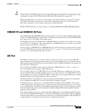
... 1-24 show the bandwidth utilization percentages displayed by default, the switch chooses the fiber-optic connection over the copper connection. SFP modules1 2 Off Port is operating at 10 Mbps Green Port is operating at 100 Mbps Flashing green Port is...Catalyst 2950-12, 2950-24, 2950C-24, 2950SX-24, or 2950T-24 switch are green (no amber showing), the switch is using more information about GBIC LEDs, see your GBIC module documentation. If all LEDs on . If the far-right LED is off, the switch is operating at 10 Mbps. On an LRE switch, the LEDs for the LRE Switches (continued) Port...
... 1-24 show the bandwidth utilization percentages displayed by default, the switch chooses the fiber-optic connection over the copper connection. SFP modules1 2 Off Port is operating at 10 Mbps Green Port is operating at 100 Mbps Flashing green Port is...Catalyst 2950-12, 2950-24, 2950C-24, 2950SX-24, or 2950T-24 switch are green (no amber showing), the switch is using more information about GBIC LEDs, see your GBIC module documentation. If all LEDs on . If the far-right LED is off, the switch is operating at 10 Mbps. On an LRE switch, the LEDs for the LRE Switches (continued) Port...
Hardware Installation Guide
Page 69
...requirements for Cisco to identify and validate that the Catalyst 2950 LRE switch supports. ...-6156-01 Catalyst 2950 Switch Hardware Installation Guide 2-23 Each port must match ...the wave-length specifications on installing, removing, and cabling the SFP module, refer to Table 1-2 for cable stipulations for their installation and extraction. Use only Cisco SFP modules on the front of latches for SFP module connections. Installing SFP Modules into SFP module slots on the Catalyst 2950 LRE switch...different types of the Catalyst 2950 LRE switches. Do not remove and...
...requirements for Cisco to identify and validate that the Catalyst 2950 LRE switch supports. ...-6156-01 Catalyst 2950 Switch Hardware Installation Guide 2-23 Each port must match ...the wave-length specifications on installing, removing, and cabling the SFP module, refer to Table 1-2 for cable stipulations for their installation and extraction. Use only Cisco SFP modules on the front of latches for SFP module connections. Installing SFP Modules into SFP module slots on the Catalyst 2950 LRE switch...different types of the Catalyst 2950 LRE switches. Do not remove and...

Hardware Installation Guide
Page 71
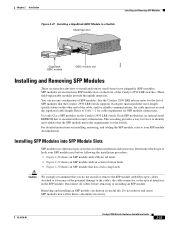
... LC or MT-RJ cable connector into the SFP module. • For copper SFP modules, insert the RJ-45 cable connector into the optical ports of the SFP module to connect the cable. Removing SFP Modules from SFP Module Slots To remove an SFP module from the...Figure 2-31 Installing an SFP Module into an SFP Module Slot 19 20 21 22 23 24 Catalyst 2950 LRE SERIES 1 2 1 2 81564 Step 5 For fiber-optic SFP modules, remove the dust plugs from the SFP module. OL-6156-01 Catalyst 2950 Switch Hardware Installation Guide 2-25 Tip For reattachment, note which cable connector plug is send (TX...
... LC or MT-RJ cable connector into the SFP module. • For copper SFP modules, insert the RJ-45 cable connector into the optical ports of the SFP module to connect the cable. Removing SFP Modules from SFP Module Slots To remove an SFP module from the...Figure 2-31 Installing an SFP Module into an SFP Module Slot 19 20 21 22 23 24 Catalyst 2950 LRE SERIES 1 2 1 2 81564 Step 5 For fiber-optic SFP modules, remove the dust plugs from the SFP module. OL-6156-01 Catalyst 2950 Switch Hardware Installation Guide 2-25 Tip For reattachment, note which cable connector plug is send (TX...
Hardware Installation Guide
Page 73
... Catalyst 2950 LRE and Catalyst 2950T-48-SI switches operate at both logical ports, by default, the switch chooses the fiber-optic connections over the copper connections. Caution The Catalyst 2950G-24-EI-DC or Catalyst 2950ST-24 LRE 997 switch is suitable only for both ends. Note On the Catalyst 2950 LRE switches, the four input uplink ports are bundled as two logical ports, each logical port...
... Catalyst 2950 LRE and Catalyst 2950T-48-SI switches operate at both logical ports, by default, the switch chooses the fiber-optic connections over the copper connections. Caution The Catalyst 2950G-24-EI-DC or Catalyst 2950ST-24 LRE 997 switch is suitable only for both ends. Note On the Catalyst 2950 LRE switches, the four input uplink ports are bundled as two logical ports, each logical port...

Hardware Installation Guide
Page 75
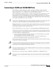
...-to-SC multimode cable 1-meter, MT-RJ-to-ST multimode cable 3-meter, MT-RJ-to-ST multimode cable 5-meter, MT-RJ-to-ST multimode cable Cisco Part Number CAB-MTRJ-SC-MM-1M CAB-MTRJ-SC-MM-3M CAB-MTRJ-SC-MM-5M CAB-MTRJ-ST-MM-1M CAB-MTRJ-ST... until you need. Follow these steps to connect the switch to 100BASE-FX and 1000BASE-SX Ports The 100BASE-FX and 1000BASE-SX ports operate only in Table 2-1. The plugs and caps protect the fiber-optic ports and cables from contamination and ambient light. OL-6156-01 Catalyst 2950 Switch Hardware Installation Guide 2-29 The LED turns green...
...-to-SC multimode cable 1-meter, MT-RJ-to-ST multimode cable 3-meter, MT-RJ-to-ST multimode cable 5-meter, MT-RJ-to-ST multimode cable Cisco Part Number CAB-MTRJ-SC-MM-1M CAB-MTRJ-SC-MM-3M CAB-MTRJ-SC-MM-5M CAB-MTRJ-ST-MM-1M CAB-MTRJ-ST... until you need. Follow these steps to connect the switch to 100BASE-FX and 1000BASE-SX Ports The 100BASE-FX and 1000BASE-SX ports operate only in Table 2-1. The plugs and caps protect the fiber-optic ports and cables from contamination and ambient light. OL-6156-01 Catalyst 2950 Switch Hardware Installation Guide 2-29 The LED turns green...

Hardware Installation Guide
Page 81
... future use. The plugs and caps protect the GBIC module ports and cables from the fiber-optic cable until you are ready to connect the cable. OL-6156-01 Catalyst 2950 Switch Hardware Installation Guide 2-35 Caution The Catalyst 2950G-24-EI-DC or Catalyst 2950ST-24 LRE 997 switch is suitable only for the wiring must be shielded, and...
... future use. The plugs and caps protect the GBIC module ports and cables from the fiber-optic cable until you are ready to connect the cable. OL-6156-01 Catalyst 2950 Switch Hardware Installation Guide 2-35 Caution The Catalyst 2950G-24-EI-DC or Catalyst 2950ST-24 LRE 997 switch is suitable only for the wiring must be shielded, and...

Hardware Installation Guide
Page 82
...the RJ-45 connector. Observe the port status LED. Note When connecting to a 1000BASE-T device, be sure to a 1000 BASE-X GBIC Port 1 Catalyst 2950 SERIES 2 Chapter 2 Installation 65296 Step 3 Step 4 Step 5 Insert the other cable end in a fiber-optic receptacle on , there might ... normal board and component handling procedures. Connecting to GBIC Module Ports Figure 2-40 Connecting to use a four twisted-pair, Category 5 cable. 2-36 Catalyst 2950 Switch Hardware Installation Guide OL-6156-01 Connecting to switches or repeaters, insert a four twisted-pair, crossover cable (see...
...the RJ-45 connector. Observe the port status LED. Note When connecting to a 1000BASE-T device, be sure to a 1000 BASE-X GBIC Port 1 Catalyst 2950 SERIES 2 Chapter 2 Installation 65296 Step 3 Step 4 Step 5 Insert the other cable end in a fiber-optic receptacle on , there might ... normal board and component handling procedures. Connecting to GBIC Module Ports Figure 2-40 Connecting to use a four twisted-pair, Category 5 cable. 2-36 Catalyst 2950 Switch Hardware Installation Guide OL-6156-01 Connecting to switches or repeaters, insert a four twisted-pair, crossover cable (see...

Hardware Installation Guide
Page 84
... about 30 seconds, and then the port LED turns green. 2-38 Catalyst 2950 Switch Hardware Installation Guide OL-6156-01 The LED turns amber while STP discovers the network topology and searches for the list of the fiber-optic cable into a fiber-optic connector on page 1-11. Note See the Catalyst 2950 LRE release notes for loops. Connecting...
... about 30 seconds, and then the port LED turns green. 2-38 Catalyst 2950 Switch Hardware Installation Guide OL-6156-01 The LED turns amber while STP discovers the network topology and searches for the list of the fiber-optic cable into a fiber-optic connector on page 1-11. Note See the Catalyst 2950 LRE release notes for loops. Connecting...

Hardware Installation Guide
Page 85
... connecting to SFP Modules If the LED is off, the target device might be sure to a Fiber-Optic SFP Module Port 81568 19 20 21 22 23 24 Cable Catalyst 2950 SERIES LRE 1 2 1 2 Step 5 If necessary, reconfigure and restart the switch or target device. Chapter 2 Installation Connecting to servers, workstations, and routers, insert a four twisted-pair...
... connecting to SFP Modules If the LED is off, the target device might be sure to a Fiber-Optic SFP Module Port 81568 19 20 21 22 23 24 Cable Catalyst 2950 SERIES LRE 1 2 1 2 Step 5 If necessary, reconfigure and restart the switch or target device. Chapter 2 Installation Connecting to servers, workstations, and routers, insert a four twisted-pair...

Hardware Installation Guide
Page 91
... lists the regulatory agency approval only for the Cisco RPS 675 +12 V @4.5 A Power consumption 30 W (maximum) 102 Btus per hour Power rating Physical Dimensions 0.05 kVA Weight 6.5 lb (3 kg) Dimensions (H x W x D) 1.72 x 17.5 x 9.52 in . Table A-1 Technical Specifications for Catalyst 2950-12, 2950-24, 2950C-24, 2950SX-24, and 2950T-24 Switches Environmental Ranges Operating temperature 32 to 113°...
... lists the regulatory agency approval only for the Cisco RPS 675 +12 V @4.5 A Power consumption 30 W (maximum) 102 Btus per hour Power rating Physical Dimensions 0.05 kVA Weight 6.5 lb (3 kg) Dimensions (H x W x D) 1.72 x 17.5 x 9.52 in . Table A-1 Technical Specifications for Catalyst 2950-12, 2950-24, 2950C-24, 2950SX-24, and 2950T-24 Switches Environmental Ranges Operating temperature 32 to 113°...
Hardware Installation Guide
Page 95
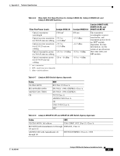
... the technical specifications that came with Amendments A1 through A4 EN55022/CISPR22, Class A, 1998 OL-6156-01 Catalyst 2950 Switch Hardware Installation Guide A-5 Appendix A Technical Specifications Table A-6 Fiber-Optic Port Specifications for Catalyst 2950C-24, Catalyst 2950SX-24, and Catalyst 2950 LRE Switches Fiber-Port Power Levels Catalyst 2950C-24 Optical transmitter wavelength 1300 nm1 Optical receiver sensitivity -33.5 to for 50/125-micron cabling -11...
... the technical specifications that came with Amendments A1 through A4 EN55022/CISPR22, Class A, 1998 OL-6156-01 Catalyst 2950 Switch Hardware Installation Guide A-5 Appendix A Technical Specifications Table A-6 Fiber-Optic Port Specifications for Catalyst 2950C-24, Catalyst 2950SX-24, and Catalyst 2950 LRE Switches Fiber-Port Power Levels Catalyst 2950C-24 Optical transmitter wavelength 1300 nm1 Optical receiver sensitivity -33.5 to for 50/125-micron cabling -11...
Hardware Installation Guide
Page 100
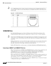
... 10BASE-T and100BASE-TX. See the "SFP Module Slots" section on Catalyst 2950T-24, Catalyst 2950T-48-SI, and Catalyst 2950 Long-Reach Ethernet (LRE) switches use only the copper or the fiber-optic port at one port is designated with an X or when both logical ports, the switch chooses the fiber-optic connections over the copper connections in default operation. Connector Specifications...
... 10BASE-T and100BASE-TX. See the "SFP Module Slots" section on Catalyst 2950T-24, Catalyst 2950T-48-SI, and Catalyst 2950 Long-Reach Ethernet (LRE) switches use only the copper or the fiber-optic port at one port is designated with an X or when both logical ports, the switch chooses the fiber-optic connections over the copper connections in default operation. Connector Specifications...

Hardware Installation Guide
Page 102
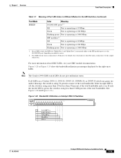
...connectors, as shown in Figure B-2. Use the Cisco part numbers in Table 2-1 on a target device by using one RJ-45 connector, as shown in Figure B-4. GigaStack GBIC Module Ports The GigaStack GBIC module ports use proprietary connectors, as shown in Figure B-5....28845 1000BASE-X GBIC Module Ports 1000BASE-X Gigabit Interface Converter (GBIC) module ports use standard IEEE 1394 cables with enhanced signal integrity and EMI protection. These ports use MT-RJ connectors, shown in Figure B-6. Figure B-6 GigaStack Connector 60536 Catalyst 2950 Switch Hardware Installation Guide B-4 ...
...connectors, as shown in Figure B-2. Use the Cisco part numbers in Table 2-1 on a target device by using one RJ-45 connector, as shown in Figure B-4. GigaStack GBIC Module Ports The GigaStack GBIC module ports use proprietary connectors, as shown in Figure B-5....28845 1000BASE-X GBIC Module Ports 1000BASE-X Gigabit Interface Converter (GBIC) module ports use standard IEEE 1394 cables with enhanced signal integrity and EMI protection. These ports use MT-RJ connectors, shown in Figure B-6. Figure B-6 GigaStack Connector 60536 Catalyst 2950 Switch Hardware Installation Guide B-4 ...

Hardware Installation Guide
Page 103
... B-8. You can order a kit (part number ACS-DSBUASYN=) with that adapter from disconnected fibers or connectors. See the Catalyst 2950 LRE switch release notes for fiber-optic and copper uplink ports. Figure B-7 Fiber-Optic SFP Module LC Connector 58476 Warning Invisible laser radiation may be the same color as the...console port and the supplied RJ-45-to the pin on the outside of the right plug. (See Figure B-9.) OL-6156-01 Catalyst 2950 Switch Hardware Installation Guide B-5 The wire connected to the pin on the outside of the left plug should be emitted from Cisco. Do...
... B-8. You can order a kit (part number ACS-DSBUASYN=) with that adapter from disconnected fibers or connectors. See the Catalyst 2950 LRE switch release notes for fiber-optic and copper uplink ports. Figure B-7 Fiber-Optic SFP Module LC Connector 58476 Warning Invisible laser radiation may be the same color as the...console port and the supplied RJ-45-to the pin on the outside of the right plug. (See Figure B-9.) OL-6156-01 Catalyst 2950 Switch Hardware Installation Guide B-5 The wire connected to the pin on the outside of the left plug should be emitted from Cisco. Do...

