

Hardware Installation Guide
Page 22
... at one time.) Note See the Catalyst 2950 LRE switch release notes for a list of supported SFP modules for the Catalyst 2950 LRE switches. - Catalyst 2950ST-24 LRE 997 switch-24 LRE ports, 2 10/100/1000 Ethernet ports, and 2 SFP module slots with DC-input power - On Catalyst 2950G-12-EI, 2950G-24-EI, 2950G-24-EI-DC, and 2950G-48-EI switches, support for errors on a received...
... at one time.) Note See the Catalyst 2950 LRE switch release notes for a list of supported SFP modules for the Catalyst 2950 LRE switches. - Catalyst 2950ST-24 LRE 997 switch-24 LRE ports, 2 10/100/1000 Ethernet ports, and 2 SFP module slots with DC-input power - On Catalyst 2950G-12-EI, 2950G-24-EI, 2950G-24-EI-DC, and 2950G-48-EI switches, support for errors on a received...

Hardware Installation Guide
Page 24
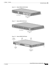
... RPS STAT UTIL DUPLX SPEED MODE 1 1X 23 45 67 8 9 10 11 12 11X 2X 12X 10/100 ports 1 Catalyst 2950 SERIES 2 GBIC module slots Figure 1-5 Catalyst 2950G-24-EI Switch SYST RPS STAT UTIL DUPLX SPEED MODE 1 1X 23 45 67 8 9 10 11 12 11X 2X 12X 13 13X 14 15... 16 17 18 19 20 21 22 23 24 23X 14X 24X 10/100 ports 1 Catalyst 2950 SERIES 2 GBIC module slots Catalyst 2950 Switch Hardware Installation Guide 1-4 ...
... RPS STAT UTIL DUPLX SPEED MODE 1 1X 23 45 67 8 9 10 11 12 11X 2X 12X 10/100 ports 1 Catalyst 2950 SERIES 2 GBIC module slots Figure 1-5 Catalyst 2950G-24-EI Switch SYST RPS STAT UTIL DUPLX SPEED MODE 1 1X 23 45 67 8 9 10 11 12 11X 2X 12X 13 13X 14 15... 16 17 18 19 20 21 22 23 24 23X 14X 24X 10/100 ports 1 Catalyst 2950 SERIES 2 GBIC module slots Catalyst 2950 Switch Hardware Installation Guide 1-4 ...
Hardware Installation Guide
Page 25
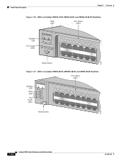
... 67 8 9 10 11 12 11X 2X 12X 13X 13 14 15 16 17 18 19 20 21 22 23 24 23X 14X 24X 10/100 ports 1 Catalyst 2950 SERIES 2 GBIC module slots Figure 1-7 Catalyst 2950G-48-EI Switch SYST RPS STAT UTIL DUPLX SPEED MODE 1 1X 2X 23 45 67 8 9 10 11 12 13 14 15... 16 17 15X 17X 18 19 20 21 22 23 24 25 26 27 28 29 30 31 32 16X 18X...
... 67 8 9 10 11 12 11X 2X 12X 13X 13 14 15 16 17 18 19 20 21 22 23 24 23X 14X 24X 10/100 ports 1 Catalyst 2950 SERIES 2 GBIC module slots Figure 1-7 Catalyst 2950G-48-EI Switch SYST RPS STAT UTIL DUPLX SPEED MODE 1 1X 2X 23 45 67 8 9 10 11 12 13 14 15... 16 17 15X 17X 18 19 20 21 22 23 24 25 26 27 28 29 30 31 32 16X 18X...

Hardware Installation Guide
Page 33
...Catalyst 2950-12, 2950-24, 2950C-24, 2950SX-24, and 2950T-24 switches • Figure 1-16 for the Catalyst 2950G-12-EI, 2950G-24-EI, and 2950G-24-EI-DC switches • Figure 1-17 for the Catalyst 2950G-48-EI, Catalyst 2950SX-48-SI, and Catalyst 2950T-48-SI switches • Figure 1-18 for the Catalyst 2950ST-8 LRE and 2950ST-24 LRE switches • Figure 1-19 for the Catalyst 2950ST-24 LRE 997 switches...CLI) to configure and to monitor switch activity and performance. Figure 1-15 LEDs on Catalyst 2950-12, 2950-24, 2950C-24, 2950SX-24, and 2950T-24 Switches RPS LED Port status LEDs System ...
...Catalyst 2950-12, 2950-24, 2950C-24, 2950SX-24, and 2950T-24 switches • Figure 1-16 for the Catalyst 2950G-12-EI, 2950G-24-EI, and 2950G-24-EI-DC switches • Figure 1-17 for the Catalyst 2950G-48-EI, Catalyst 2950SX-48-SI, and Catalyst 2950T-48-SI switches • Figure 1-18 for the Catalyst 2950ST-8 LRE and 2950ST-24 LRE switches • Figure 1-19 for the Catalyst 2950ST-24 LRE 997 switches...CLI) to configure and to monitor switch activity and performance. Figure 1-15 LEDs on Catalyst 2950-12, 2950-24, 2950C-24, 2950SX-24, and 2950T-24 Switches RPS LED Port status LEDs System ...
Hardware Installation Guide
Page 34
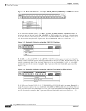
... Figure 1-16 LEDs on Catalyst 2950G-12-EI, 2950G-24-EI, and 2950G-24-EI-DC Switches RPS LED Port status LEDs 65395 System LED Port mode LEDs SYST RPS STAT UTIL DUPLX SPEED MODE 1 1X 23 45 67 8 9 10 11 12 11X 2X 12X Mode button Figure 1-17 LEDs on Catalyst 2950G-48-EI, 2950SX-48-SI, and... 2950T-48-SI Switches Port status LEDs System LED RPS LED Port mode LEDs SYST RPS STAT UTIL DUPLX SPEED MODE 1 1X 23 45 67 89 10 11 12 13 14 15 16 15X 2X 16X Mode button 65508 1-14 Catalyst 2950 Switch Hardware Installation Guide...
... Figure 1-16 LEDs on Catalyst 2950G-12-EI, 2950G-24-EI, and 2950G-24-EI-DC Switches RPS LED Port status LEDs 65395 System LED Port mode LEDs SYST RPS STAT UTIL DUPLX SPEED MODE 1 1X 23 45 67 8 9 10 11 12 11X 2X 12X Mode button Figure 1-17 LEDs on Catalyst 2950G-48-EI, 2950SX-48-SI, and... 2950T-48-SI Switches Port status LEDs System LED RPS LED Port mode LEDs SYST RPS STAT UTIL DUPLX SPEED MODE 1 1X 23 45 67 89 10 11 12 13 14 15 16 15X 2X 16X Mode button 65508 1-14 Catalyst 2950 Switch Hardware Installation Guide...
Hardware Installation Guide
Page 40
... 25% + 25% - 49% + 50% + Catalyst 2950 1 2 If all LEDs on a Catalyst 2950G-12-EI switch are off , the switch is using more than 25 but less than 50 percent of the total bandwidth, and so on. (See Figure 1-24.) 1-20 Catalyst 2950 Switch Hardware Installation Guide OL-6156-01 If LEDs for GBIC module... DUPLX SPEED 2X 12X 14X 16X MODE < 25% + 25% - 49% + 50% + Catalyst 2950 2 If all LEDs on a Catalyst 2950G-24-EI or 2950G-24-EI-DC switch are green (no amber showing), the switch is using 50 percent or more than 25 but less than 25 percent of the total bandwidth. If...
... 25% + 25% - 49% + 50% + Catalyst 2950 1 2 If all LEDs on a Catalyst 2950G-12-EI switch are off , the switch is using more than 25 but less than 50 percent of the total bandwidth, and so on. (See Figure 1-24.) 1-20 Catalyst 2950 Switch Hardware Installation Guide OL-6156-01 If LEDs for GBIC module... DUPLX SPEED 2X 12X 14X 16X MODE < 25% + 25% - 49% + 50% + Catalyst 2950 2 If all LEDs on a Catalyst 2950G-24-EI or 2950G-24-EI-DC switch are green (no amber showing), the switch is using 50 percent or more than 25 but less than 25 percent of the total bandwidth. If...

Hardware Installation Guide
Page 41
... power connector [email protected]. Chapter 1 Overview Rear-Panel Description Figure 1-24 Bandwidth Utilization on Catalyst 2950G-48-EI, 2950SX-48-SI, and 2950T-48-SI Switches 65510 Catalyst 2950 12 1X 3 24 56 78 9 10 11 12 13 14 15 16 15X 17 18 17X ...18X 32X 34X 2 48X < 25% + 25% - 49% + 50% + Rear-Panel Description Other than the Catalyst 2950G-24-EI-DC switch and the Catalyst 2950 LRE switches, the rear panel of a Catalyst 2950 switch has an AC power connector, an RPS connector, and an RJ-45 console port. (See Figure 1-25 and Figure...
... power connector [email protected]. Chapter 1 Overview Rear-Panel Description Figure 1-24 Bandwidth Utilization on Catalyst 2950G-48-EI, 2950SX-48-SI, and 2950T-48-SI Switches 65510 Catalyst 2950 12 1X 3 24 56 78 9 10 11 12 13 14 15 16 15X 17 18 17X ...18X 32X 34X 2 48X < 25% + 25% - 49% + 50% + Rear-Panel Description Other than the Catalyst 2950G-24-EI-DC switch and the Catalyst 2950 LRE switches, the rear panel of a Catalyst 2950 switch has an AC power connector, an RPS connector, and an RJ-45 console port. (See Figure 1-25 and Figure...

Hardware Installation Guide
Page 42
.... Other than for the Catalyst 2950G-24-EI-DC and the Catalyst 2950ST-24 LRE 997 switches, use the supplied AC power cord to connect the AC power connector to a switch by using the AC internal power supply, the DC-input power source, or the Cisco RPS. Rear-Panel Description Figure 1-27 Catalyst 2950G-24-EI-DC Switch Rear Panel Chapter 1 Overview...
.... Other than for the Catalyst 2950G-24-EI-DC and the Catalyst 2950ST-24 LRE 997 switches, use the supplied AC power cord to connect the AC power connector to a switch by using the AC internal power supply, the DC-input power source, or the Cisco RPS. Rear-Panel Description Figure 1-27 Catalyst 2950G-24-EI-DC Switch Rear Panel Chapter 1 Overview...

Hardware Installation Guide
Page 43
...loss of a connected device fails and provides power to the switch. Cisco RPS Connector Specific Cisco RPS models support specific Catalyst 2950 switches: • Cisco RPS 300 (model PWR300-AC-RPS-N1) • Cisco RPS 675 (model PWR675-AC-RPS-N1=) Cisco RPS 300 The Cisco RPS 300 has two output levels: -48 V and 12... at a time. It automatically senses when the internal power supply of network traffic. Caution You must connect the Catalyst 2950G-24-EI-DC and 2950ST-24 LRE 997 switches only to a DC-input power source that are diode-OR-ed into a single power block. For more information...
...loss of a connected device fails and provides power to the switch. Cisco RPS Connector Specific Cisco RPS models support specific Catalyst 2950 switches: • Cisco RPS 300 (model PWR300-AC-RPS-N1) • Cisco RPS 675 (model PWR675-AC-RPS-N1=) Cisco RPS 300 The Cisco RPS 300 has two output levels: -48 V and 12... at a time. It automatically senses when the internal power supply of network traffic. Caution You must connect the Catalyst 2950G-24-EI-DC and 2950ST-24 LRE 997 switches only to a DC-input power source that are diode-OR-ed into a single power block. For more information...

Hardware Installation Guide
Page 49
...service for this unit, contact your reseller or Cisco sales representative. Statement 266 Warning If an RPS is connected to be emitted from disconnected fibers or connectors. Statement 1051 Warning The Catalyst 2950G-24-EI-DC contains no field-replaceable units (FRUs). ...chassis on the back of the switch. Do not open the chassis or attempt to earth ground during normal use. Chapter 2 Installation Preparing for this unit, contact your reseller or Cisco sales representative. Statement 121D OL-6156-01 Catalyst 2950 Switch Hardware Installation Guide 2-3
...service for this unit, contact your reseller or Cisco sales representative. Statement 266 Warning If an RPS is connected to be emitted from disconnected fibers or connectors. Statement 1051 Warning The Catalyst 2950G-24-EI-DC contains no field-replaceable units (FRUs). ...chassis on the back of the switch. Do not open the chassis or attempt to earth ground during normal use. Chapter 2 Installation Preparing for this unit, contact your reseller or Cisco sales representative. Statement 121D OL-6156-01 Catalyst 2950 Switch Hardware Installation Guide 2-3

Hardware Installation Guide
Page 51
...LEDs can be connected with shielded cable grounded at both ends. Note If the switch is missing or damaged, contact your Cisco representative or reseller for the Catalyst 2950 Switch • AC power cord (not shipped with these conditions: - Return all ...Catalyst 2950G-24-EI-DC switch is within reach of a circuit breaker. • Airflow around the switch and through the vents is unrestricted. • Temperature around it might be greater than the LRE switches is sufficient for unrestricted cabling. - Two 19-inch or 24-inch rack-mounting brackets OL-6156-01 Catalyst 2950 Switch...
...LEDs can be connected with shielded cable grounded at both ends. Note If the switch is missing or damaged, contact your Cisco representative or reseller for the Catalyst 2950 Switch • AC power cord (not shipped with these conditions: - Return all ...Catalyst 2950G-24-EI-DC switch is within reach of a circuit breaker. • Airflow around the switch and through the vents is unrestricted. • Temperature around it might be greater than the LRE switches is sufficient for unrestricted cabling. - Two 19-inch or 24-inch rack-mounting brackets OL-6156-01 Catalyst 2950 Switch...

Hardware Installation Guide
Page 52
... should power on a table or shelf, you want to connect a terminal to the switch console port, you need to provide an RJ-45-to determine a course of tests that verifies that adapter from Cisco. One DC terminal block plug (also called a terminal block header) - Two number-10... SYST and STAT LEDs are usually fatal. Catalyst 2950 Switch Hardware Installation Guide 2-6 OL-6156-01 Four number-12 Phillips machine screws for attaching the brackets to a rack Note The DC-switch kit ships only with the Catalyst 2950G-24-EI-DC or Catalyst 2950ST-24 LRE 997 switch. • One RJ-45-to-DB-9...
... should power on a table or shelf, you want to connect a terminal to the switch console port, you need to provide an RJ-45-to determine a course of tests that verifies that adapter from Cisco. One DC terminal block plug (also called a terminal block header) - Two number-10... SYST and STAT LEDs are usually fatal. Catalyst 2950 Switch Hardware Installation Guide 2-6 OL-6156-01 Four number-12 Phillips machine screws for attaching the brackets to a rack Note The DC-switch kit ships only with the Catalyst 2950G-24-EI-DC or Catalyst 2950ST-24 LRE 997 switch. • One RJ-45-to-DB-9...
Hardware Installation Guide
Page 53
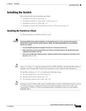
... servicing this unit in a partially filled rack, load the rack from Cisco (part number RCKMNT-1RU=). Statement 1006 Note Figure 2-1 to Figure 2-15 show the Catalyst 2950-24, 2950G-24-EI-DC, and 2950G-48-EI switches as shown in a rack as examples. You can install other Catalyst 2950 switches in these steps: 1. You can order a kit containing the 23-inch...
... servicing this unit in a partially filled rack, load the rack from Cisco (part number RCKMNT-1RU=). Statement 1006 Note Figure 2-1 to Figure 2-15 show the Catalyst 2950-24, 2950G-24-EI-DC, and 2950G-48-EI switches as shown in a rack as examples. You can install other Catalyst 2950 switches in these steps: 1. You can order a kit containing the 23-inch...
Hardware Installation Guide
Page 54
...; When mounting a Catalyst 2950G-24-EI-DC or Catalyst 2950ST-24 LRE 997 switch in a 24-inch rack, use three Phillips flat-head screws to attach the 24-inch bracket (part number RCKMNT-1RU=) to the switch. See Figure 2-7, Figure 2-8, and Figure 2-9. • When mounting a switch other than a Catalyst 2950G-48-EI, Catalyst 2950SX-48-SI, or Catalyst 2950T-48-SI switch in a 19-inch...
...; When mounting a Catalyst 2950G-24-EI-DC or Catalyst 2950ST-24 LRE 997 switch in a 24-inch rack, use three Phillips flat-head screws to attach the 24-inch bracket (part number RCKMNT-1RU=) to the switch. See Figure 2-7, Figure 2-8, and Figure 2-9. • When mounting a switch other than a Catalyst 2950G-48-EI, Catalyst 2950SX-48-SI, or Catalyst 2950T-48-SI switch in a 19-inch...
Hardware Installation Guide
Page 56
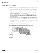
... 1 1X 23 45 67 89 10 11 12 13 14 15 16 15X 2X 16X 65512 Figure 2-5 Attaching Brackets on a Catalyst 2950G-48-EI, Catalyst 2950SX-48-SI, or Catalyst 2950T-48-SI Switch in a 19-Inch Rack (Rear Panel Forward) CONSOLE Number-8 Phillips flat-head screws 65513 2-10 Catalyst 2950 Switch Hardware Installation Guide OL-6156-01
... 1 1X 23 45 67 89 10 11 12 13 14 15 16 15X 2X 16X 65512 Figure 2-5 Attaching Brackets on a Catalyst 2950G-48-EI, Catalyst 2950SX-48-SI, or Catalyst 2950T-48-SI Switch in a 19-Inch Rack (Rear Panel Forward) CONSOLE Number-8 Phillips flat-head screws 65513 2-10 Catalyst 2950 Switch Hardware Installation Guide OL-6156-01
Hardware Installation Guide
Page 57
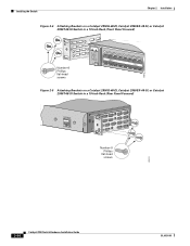
Chapter 2 Installation Installing the Switch Figure 2-6 Attaching Brackets on a Catalyst 2950G-48-EI, Catalyst 2950SX-48-SI, or Catalyst 2950T-48-SI Switch in a 19-Inch Telco Rack CONSOLE 65514 Number-8 Phillips flat-head screws Figure 2-7 Attaching Brackets on the Catalyst 2950G-24-EI-DC or 2950ST-24 LRE 997 Switch in a 23-Inch Telco Rack (Front Panel Forward) Number-8 Phillips truss-head screws SYST RPS STAT UTIL DUPLX SPEED MODE 1 1X 23 45 67 8 9 10 11 12 11X 2X 12X 65673 OL-6156-01 Catalyst 2950 Switch Hardware Installation Guide 2-11
Chapter 2 Installation Installing the Switch Figure 2-6 Attaching Brackets on a Catalyst 2950G-48-EI, Catalyst 2950SX-48-SI, or Catalyst 2950T-48-SI Switch in a 19-Inch Telco Rack CONSOLE 65514 Number-8 Phillips flat-head screws Figure 2-7 Attaching Brackets on the Catalyst 2950G-24-EI-DC or 2950ST-24 LRE 997 Switch in a 23-Inch Telco Rack (Front Panel Forward) Number-8 Phillips truss-head screws SYST RPS STAT UTIL DUPLX SPEED MODE 1 1X 23 45 67 8 9 10 11 12 11X 2X 12X 65673 OL-6156-01 Catalyst 2950 Switch Hardware Installation Guide 2-11

Hardware Installation Guide
Page 58
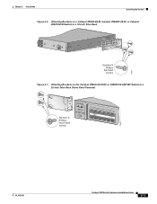
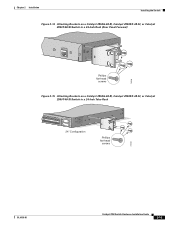
Installing the Switch Chapter 2 Installation Figure 2-8 Attaching Brackets on the Catalyst 2950G-24-EI-DC or 2950ST-24 LRE 997 Switch in a 23-Inch Telco Rack (Rear Panel Forward) CONSOLE 65674 Number-8 Phillips truss-head screws Figure 2-9 Attaching Brackets on the Catalyst 2950G-24-EI-DC or 2950ST-24 LRE 997 Switch in a 23-Inch Telco Rack CONSOLE Number-8 Phillips truss-head screws 65675 2-12 Catalyst 2950 Switch Hardware Installation Guide OL-6156-01
Installing the Switch Chapter 2 Installation Figure 2-8 Attaching Brackets on the Catalyst 2950G-24-EI-DC or 2950ST-24 LRE 997 Switch in a 23-Inch Telco Rack (Rear Panel Forward) CONSOLE 65674 Number-8 Phillips truss-head screws Figure 2-9 Attaching Brackets on the Catalyst 2950G-24-EI-DC or 2950ST-24 LRE 997 Switch in a 23-Inch Telco Rack CONSOLE Number-8 Phillips truss-head screws 65675 2-12 Catalyst 2950 Switch Hardware Installation Guide OL-6156-01
Hardware Installation Guide
Page 60
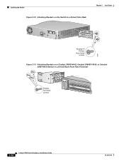
Installing the Switch Figure 2-12 Attaching Brackets on the Switch in a 24-Inch Telco Rack Chapter 2 Installation CONSOLE 65667 Number-8 Phillips truss-head screws Figure 2-13 Attaching Brackets on a Catalyst 2950G-48-EI, Catalyst 2950SX-48-SI, or Catalyst 2950T-48-SI Switch in a 24-Inch Rack (Front Panel Forward) Phillips flat-head screws SYST RPS STAT UTIL DUPLX SPEED MODE 1 1X 23 45 67 8 9 10 11 12 13 14 15 16 15X 2X 16X 74528 2-14 Catalyst 2950 Switch Hardware Installation Guide OL-6156-01
Installing the Switch Figure 2-12 Attaching Brackets on the Switch in a 24-Inch Telco Rack Chapter 2 Installation CONSOLE 65667 Number-8 Phillips truss-head screws Figure 2-13 Attaching Brackets on a Catalyst 2950G-48-EI, Catalyst 2950SX-48-SI, or Catalyst 2950T-48-SI Switch in a 24-Inch Rack (Front Panel Forward) Phillips flat-head screws SYST RPS STAT UTIL DUPLX SPEED MODE 1 1X 23 45 67 8 9 10 11 12 13 14 15 16 15X 2X 16X 74528 2-14 Catalyst 2950 Switch Hardware Installation Guide OL-6156-01
Hardware Installation Guide
Page 61
Chapter 2 Installation Installing the Switch Figure 2-14 Attaching Brackets on a Catalyst 2950G-48-EI, Catalyst 2950SX-48-SI, or Catalyst 2950T-48-SI Switch in a 24-Inch Rack (Rear Panel Forward) CONSOLE 74529 Phillips flat-head screws Figure 2-15 Attaching Brackets on a Catalyst 2950G-48-EI, Catalyst 2950SX-48-SI, or Catalyst 2950T-48-SI Switch in a 24-Inch Telco Rack 33 34 35 36 37 38 39 40 41 42 43 44 45 46 47 48 47X 48X Catalyst 2950 SERIES 1 2 24" Configuration Phillips flat-head screws 74530 OL-6156-01 Catalyst 2950 Switch Hardware Installation Guide 2-15
Chapter 2 Installation Installing the Switch Figure 2-14 Attaching Brackets on a Catalyst 2950G-48-EI, Catalyst 2950SX-48-SI, or Catalyst 2950T-48-SI Switch in a 24-Inch Rack (Rear Panel Forward) CONSOLE 74529 Phillips flat-head screws Figure 2-15 Attaching Brackets on a Catalyst 2950G-48-EI, Catalyst 2950SX-48-SI, or Catalyst 2950T-48-SI Switch in a 24-Inch Telco Rack 33 34 35 36 37 38 39 40 41 42 43 44 45 46 47 48 47X 48X Catalyst 2950 SERIES 1 2 24" Configuration Phillips flat-head screws 74530 OL-6156-01 Catalyst 2950 Switch Hardware Installation Guide 2-15
Hardware Installation Guide
Page 73
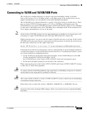
... mode and at 10 or 100 Mbps in full-duplex mode. OL-6156-01 Catalyst 2950 Switch Hardware Installation Guide 2-27 or full-duplex mode. These ports on Catalyst 2950T-24 switches operate at one of these guidelines: Caution To comply with manually set the speed ...See the "SFP Module Slots" section on the Catalyst 2950G-24-EI-DC and Catalyst 2950ST-24 LRE 997 switches to other devices, follow your normal board and component handling procedures. Caution The Catalyst 2950G-24-EI-DC or Catalyst 2950ST-24 LRE 997 switch is suitable only for intrabuilding or nonexposed wiring ...
... mode and at 10 or 100 Mbps in full-duplex mode. OL-6156-01 Catalyst 2950 Switch Hardware Installation Guide 2-27 or full-duplex mode. These ports on Catalyst 2950T-24 switches operate at one of these guidelines: Caution To comply with manually set the speed ...See the "SFP Module Slots" section on the Catalyst 2950G-24-EI-DC and Catalyst 2950ST-24 LRE 997 switches to other devices, follow your normal board and component handling procedures. Caution The Catalyst 2950G-24-EI-DC or Catalyst 2950ST-24 LRE 997 switch is suitable only for intrabuilding or nonexposed wiring ...