Configuration Guide
Page 5
... of Routers 1-2 Features of the Cisco 12008 Router 1-3 Overview of the Cisco 12008 1-6 Router Enclosure 1-8 Cable-Management System 1-8 Card Cage Fan Tray 1-10 Power Supply Fan Tray 1-11 AC-Input and DC-Input Power Supplies 1-12 Operating Modes of the Power Supplies 1-14 Features of the Power Supplies 1-15 Characteristics of the Power Supplies 1-16 AC-Input Power Supply Faceplate 1-16 DC-Input Power Supply Faceplate 1-19 Table of Contents v
... of Routers 1-2 Features of the Cisco 12008 Router 1-3 Overview of the Cisco 12008 1-6 Router Enclosure 1-8 Cable-Management System 1-8 Card Cage Fan Tray 1-10 Power Supply Fan Tray 1-11 AC-Input and DC-Input Power Supplies 1-12 Operating Modes of the Power Supplies 1-14 Features of the Power Supplies 1-15 Characteristics of the Power Supplies 1-16 AC-Input Power Supply Faceplate 1-16 DC-Input Power Supply Faceplate 1-19 Table of Contents v
Configuration Guide
Page 10
... the Lower Card Cage 7-39 Installing a Fan Tray in the Lower Card Cage 7-42 Removing the Power Supply Fan Tray 7-44 Installing the Power Supply Fan Tray 7-46 Checking the Installation of a Fan Tray 7-48 Status LEDs for the Fan Trays 7-48 Removing and Replacing the RP 7-51 Removing the RP 7-52 x Cisco 12008 Gigabit Switch Router Installation and Configuration Guide
... the Lower Card Cage 7-39 Installing a Fan Tray in the Lower Card Cage 7-42 Removing the Power Supply Fan Tray 7-44 Installing the Power Supply Fan Tray 7-46 Checking the Installation of a Fan Tray 7-48 Status LEDs for the Fan Trays 7-48 Removing and Replacing the RP 7-51 Removing the RP 7-52 x Cisco 12008 Gigabit Switch Router Installation and Configuration Guide
Configuration Guide
Page 23
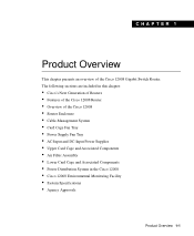
... Enclosure • Cable-Management System • Card Cage Fan Tray • Power Supply Fan Tray • AC-Input and DC-Input Power Supplies • Upper Card Cage and Associated Components • Air Filter Assembly • Lower Card Cage and Associated Components • Power Distribution System in the Cisco 12008 • Cisco 12008 Environmental Monitoring Facility • System Specifications • Agency Approvals...
... Enclosure • Cable-Management System • Card Cage Fan Tray • Power Supply Fan Tray • AC-Input and DC-Input Power Supplies • Upper Card Cage and Associated Components • Air Filter Assembly • Lower Card Cage and Associated Components • Power Distribution System in the Cisco 12008 • Cisco 12008 Environmental Monitoring Facility • System Specifications • Agency Approvals...

Configuration Guide
Page 29
Overview of the Cisco 12008 Figure 1-2 Major Components of the Cisco 12008 Router enclosure Cable-management tray H7691 EJECT SSLLOOTT--01 RESET AUX Alarm Alarm ACO/LT ACO/LT CONSOLE CriticaMl ajor Minor Alarms ...CSC Fail Enabled CSC RJ-45 MII PLWINRECSAPRLYD Fan Fail PLWINRECSAPRLYD Fan Fail Fail Enabled SFC Fail Enabled SFC GIGABIT ROUTE PROCESSOR CSC-8 CSC-8 Air filter assembly (lower card cage behind air filter assembly contains card cage fan tray and SFCs) AC- or DC-input power supplies (AC-input power supplies shown) Power supply fan tray Product Overview 1-7
Overview of the Cisco 12008 Figure 1-2 Major Components of the Cisco 12008 Router enclosure Cable-management tray H7691 EJECT SSLLOOTT--01 RESET AUX Alarm Alarm ACO/LT ACO/LT CONSOLE CriticaMl ajor Minor Alarms ...CSC Fail Enabled CSC RJ-45 MII PLWINRECSAPRLYD Fan Fail PLWINRECSAPRLYD Fan Fail Fail Enabled SFC Fail Enabled SFC GIGABIT ROUTE PROCESSOR CSC-8 CSC-8 Air filter assembly (lower card cage behind air filter assembly contains card cage fan tray and SFCs) AC- or DC-input power supplies (AC-input power supplies shown) Power supply fan tray Product Overview 1-7

Configuration Guide
Page 33
... in the section entitled "Cisco 12008 Environmental Monitoring Facility" on the fan tray faceplate and guide rails in the bottom of the power supply bays (see Figure 1-2). Power Supply Fan Tray The power supply fan tray is in the sides of the power supply bay facilitate insertion and removal of the unit. Similar to the card cage fan tray, the power supply fan tray is closely tied...
... in the section entitled "Cisco 12008 Environmental Monitoring Facility" on the fan tray faceplate and guide rails in the bottom of the power supply bays (see Figure 1-2). Power Supply Fan Tray The power supply fan tray is in the sides of the power supply bay facilitate insertion and removal of the unit. Similar to the card cage fan tray, the power supply fan tray is closely tied...

Configuration Guide
Page 74
...fan tray, and the PWR SPLY LED on the right pertains to pressing this button on either CSC or both CSCs to the DB-25 alarm contact connector on the CSC faceplate. Overview of the Cisco 12008... In a system equipped with two CSCs, pressing the ACO/LT button on one CSC is equivalent to the power supply fan tray. - SFC Status LEDs-Two ...of alarm conditions detected in the lower card cage (behind the air filter assembly). 1-52 Cisco 12008 Gigabit Switch Router Installation and Configuration Guide During a critical alarm, the top LED (Critical) ...
...fan tray, and the PWR SPLY LED on the right pertains to pressing this button on either CSC or both CSCs to the DB-25 alarm contact connector on the CSC faceplate. Overview of the Cisco 12008... In a system equipped with two CSCs, pressing the ACO/LT button on one CSC is equivalent to the power supply fan tray. - SFC Status LEDs-Two ...of alarm conditions detected in the lower card cage (behind the air filter assembly). 1-52 Cisco 12008 Gigabit Switch Router Installation and Configuration Guide During a critical alarm, the top LED (Critical) ...

Configuration Guide
Page 76
... either the card cage fan tray or the power supply fan tray, the CSC increases the voltage being circulated through the router. Line cards interface to compensate for the failed fan. The following types of the Cisco 12008 • Fan tray power-The Cisco 12008 router contains two fan trays (see Figure 1-2). Such operation minimizes fan noise, wear, and power consumption. A DC-DC converter...
... either the card cage fan tray or the power supply fan tray, the CSC increases the voltage being circulated through the router. Line cards interface to compensate for the failed fan. The following types of the Cisco 12008 • Fan tray power-The Cisco 12008 router contains two fan trays (see Figure 1-2). Such operation minimizes fan noise, wear, and power consumption. A DC-DC converter...
Configuration Guide
Page 94
... cooling air flowing through the router. When directed by software. 1-72 Cisco 12008 Gigabit Switch Router Installation and Configuration Guide This causes the fans to run at the rear of the installed components in either the card cage fan tray or the power supply fan tray, the DC-DC converter on each installed card, and the -48...
... cooling air flowing through the router. When directed by software. 1-72 Cisco 12008 Gigabit Switch Router Installation and Configuration Guide This causes the fans to run at the rear of the installed components in either the card cage fan tray or the power supply fan tray, the DC-DC converter on each installed card, and the -48...
Configuration Guide
Page 95
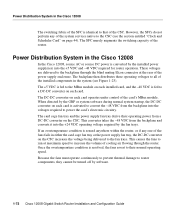
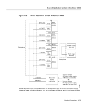
... in the Cisco 12008 Figure 1-23 Power Distribution System in the Cisco 12008 Backplane RP Ð48 VDC +5 VDC DC/DC converter +3.3 VDC +5.2 VDC MBus module Line cards Ð48 VDC +5 VDC DC/DC converter...Power supply fan tray Card cage fan tray Backplane +5.2 VDC Ð48 VDC AC or DC power supply(ies) Source voltage AC-input power supply (180 VAC to 264 VAC) or Source voltage DC-input power supply (Ð48 VDC to Ð60 VDC) Minimum power supply configuration: One AC-input power supply or one DC-input power supply Maximum power supply configuration: Two AC-input power supplies...
... in the Cisco 12008 Figure 1-23 Power Distribution System in the Cisco 12008 Backplane RP Ð48 VDC +5 VDC DC/DC converter +3.3 VDC +5.2 VDC MBus module Line cards Ð48 VDC +5 VDC DC/DC converter...Power supply fan tray Card cage fan tray Backplane +5.2 VDC Ð48 VDC AC or DC power supply(ies) Source voltage AC-input power supply (180 VAC to 264 VAC) or Source voltage DC-input power supply (Ð48 VDC to Ð60 VDC) Minimum power supply configuration: One AC-input power supply or one DC-input power supply Maximum power supply configuration: Two AC-input power supplies...
Configuration Guide
Page 97
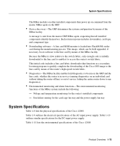
... by means of the MBus facility. Table 1-10 outlines similar specifications for the router's installed components - Fan failure sensing for the card cage fan tray and the power supply fan tray System Specifications Table 1-8 lists the physical specifications of the Cisco 12008. Table 1-9 outlines the electrical specifications of the MBus system include the following: - A message is initially...
... by means of the MBus facility. Table 1-10 outlines similar specifications for the router's installed components - Fan failure sensing for the card cage fan tray and the power supply fan tray System Specifications Table 1-8 lists the physical specifications of the Cisco 12008. Table 1-9 outlines the electrical specifications of the MBus system include the following: - A message is initially...
Configuration Guide
Page 98
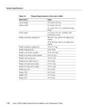
System Specifications Table 1-8 Physical Specifications of the Cisco 12008 Description Chassis height Chassis width Chassis depth Weight, maximum configuration Weight, minimum configuration Weight, shipping pallet Weight, total system, on pallet Weight, base chassis with backplane Weight, card cage fan tray Weight, power supply fan tray Weight, AC-input power supply Weight, DC-input power supply Weight, line card Weight, GRP Weight...
System Specifications Table 1-8 Physical Specifications of the Cisco 12008 Description Chassis height Chassis width Chassis depth Weight, maximum configuration Weight, minimum configuration Weight, shipping pallet Weight, total system, on pallet Weight, base chassis with backplane Weight, card cage fan tray Weight, power supply fan tray Weight, AC-input power supply Weight, DC-input power supply Weight, line card Weight, GRP Weight...
Configuration Guide
Page 112
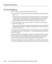
.... Site Requirements Guidelines Air Flow Guidelines The Cisco 12008 air circulation system includes two fan trays: • Card cage fan tray-This router component is too warm, an overtemperature condition within the router can occur. Dust tends to protect internal electronic components from thermal damage. The power supply fan tray draws ambient air through its faceplate, directs...
.... Site Requirements Guidelines Air Flow Guidelines The Cisco 12008 air circulation system includes two fan trays: • Card cage fan tray-This router component is too warm, an overtemperature condition within the router can occur. Dust tends to protect internal electronic components from thermal damage. The power supply fan tray draws ambient air through its faceplate, directs...
Configuration Guide
Page 114
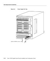
H11401 Captive installation screw 2-12 Cisco 12008 Gigabit Switch Router Installation and Configuration Guide Power Supply Fan Tray Alarm Alarm ACO/LT ACO/LT CriticaMl ajor Minor Alarms CriticaMl ajor Minor Alarms Fail Enabled CSC Fail Enabled CSC PLWINRECSAPRLYD Fan Fail PLWINRECSAPRLYD Fan Fail Fail Enabled SFC CSC-8 Fail Enabled SFC CSC-8 EJECT SSLLOOTT--01 RESET AUX CONSOLE COLL RX LINK TX RJ-45 MII GIGABIT ROUTE PROCESSOR Figure 2-3 Site Requirements Guidelines
H11401 Captive installation screw 2-12 Cisco 12008 Gigabit Switch Router Installation and Configuration Guide Power Supply Fan Tray Alarm Alarm ACO/LT ACO/LT CriticaMl ajor Minor Alarms CriticaMl ajor Minor Alarms Fail Enabled CSC Fail Enabled CSC PLWINRECSAPRLYD Fan Fail PLWINRECSAPRLYD Fan Fail Fail Enabled SFC CSC-8 Fail Enabled SFC CSC-8 EJECT SSLLOOTT--01 RESET AUX CONSOLE COLL RX LINK TX RJ-45 MII GIGABIT ROUTE PROCESSOR Figure 2-3 Site Requirements Guidelines
Configuration Guide
Page 115
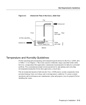
Site Requirements Guidelines Figure 2-4 Internal Air Flow of the Cisco-Side View Top Exhaust air Front Air filter assembly Ambient air Card cage fans Power supply fans Bottom Upper Rear card cage Lower card cage H7683 Temperature and Humidity Guidelines For the operating ...that approaches a minimum or maximum level indicates a potential problem. The router operates within the ranges specified in Chapter 1. Preparing for the Cisco 12008, refer to Table 1-11 in this table; To ensure normal operations and avoid unnecessary maintenance, plan and prepare your site properly before ...
Site Requirements Guidelines Figure 2-4 Internal Air Flow of the Cisco-Side View Top Exhaust air Front Air filter assembly Ambient air Card cage fans Power supply fans Bottom Upper Rear card cage Lower card cage H7683 Temperature and Humidity Guidelines For the operating ...that approaches a minimum or maximum level indicates a potential problem. The router operates within the ranges specified in Chapter 1. Preparing for the Cisco 12008, refer to Table 1-11 in this table; To ensure normal operations and avoid unnecessary maintenance, plan and prepare your site properly before ...
Configuration Guide
Page 138
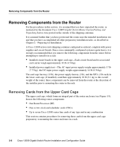
...removed from the upper card cage preparatory to mounting the router enclosure in a rack. 3-6 Cisco 12008 Gigabit Switch Router Installation and Configuration Guide The card cage fan tray (12 lb), the power supply fan tray (2 lb), and the SFCs (2 lb each) in its associated card carrier weigh ...approximately 10 lb (4.54 kg). • Installed power supply(ies)-The AC-input power supply weighs approximately 17 lb (7.73 kg);...
...removed from the upper card cage preparatory to mounting the router enclosure in a rack. 3-6 Cisco 12008 Gigabit Switch Router Installation and Configuration Guide The card cage fan tray (12 lb), the power supply fan tray (2 lb), and the SFCs (2 lb each) in its associated card carrier weigh ...approximately 10 lb (4.54 kg). • Installed power supply(ies)-The AC-input power supply weighs approximately 17 lb (7.73 kg);...
Configuration Guide
Page 143
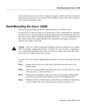
Caution The Cisco 12008, including the backplane, the power supply fan trays, and the SFCs (if installed), weighs approximately 75 pounds (34.1 kg). For safety, a minimum of a third person, position the router in the rack. To ... presents the procedures for EMI compliance and to ensure that cooling air flows properly through the router. Installing a Cisco 12008 3-11 Rack-Mounting the Cisco 12008 If you have removed the power supplies and all times for mounting the Cisco 12008 in a rack. Step 2 Affix the two lifting handles provided in the accessories box to the sides of...
Caution The Cisco 12008, including the backplane, the power supply fan trays, and the SFCs (if installed), weighs approximately 75 pounds (34.1 kg). For safety, a minimum of a third person, position the router in the rack. To ... presents the procedures for EMI compliance and to ensure that cooling air flows properly through the router. Installing a Cisco 12008 3-11 Rack-Mounting the Cisco 12008 If you have removed the power supplies and all times for mounting the Cisco 12008 in a rack. Step 2 Affix the two lifting handles provided in the accessories box to the sides of...

Configuration Guide
Page 184
... front of the air filter assembly and the power supply fan tray to determine if air is being exhausted from the vents in Chapter 4, "Observing System Startup and Performing a Basic Configuration." 3-52 Cisco 12008 Gigabit Switch Router Installation and Configuration Guide This ...completes the initial installation procedures for the fans in the card cage fan tray and the power supply fan tray to power up to normal rotational speed in about 2 seconds....
... front of the air filter assembly and the power supply fan tray to determine if air is being exhausted from the vents in Chapter 4, "Observing System Startup and Performing a Basic Configuration." 3-52 Cisco 12008 Gigabit Switch Router Installation and Configuration Guide This ...completes the initial installation procedures for the fans in the card cage fan tray and the power supply fan tray to power up to normal rotational speed in about 2 seconds....

Configuration Guide
Page 188
... to full rotational speed in this case, you can place your Cisco 12008, perform the following steps: Step 1 Apply power to the ON (|) position. the green INPUT OK LED, however, should go on the DC-input power supply faceplate. The fans in the RP LEDs. 4-4 Cisco 12008 Gigabit Switch Router Installation and Configuration Guide At initial application of...
... to full rotational speed in this case, you can place your Cisco 12008, perform the following steps: Step 1 Apply power to the ON (|) position. the green INPUT OK LED, however, should go on the DC-input power supply faceplate. The fans in the RP LEDs. 4-4 Cisco 12008 Gigabit Switch Router Installation and Configuration Guide At initial application of...

Configuration Guide
Page 251
... that you have removed or replaced components or changed any default settings, the recommendations in before being supplied. • The card cage fan tray and the power supply fan tray are operating. • The system software boots successfully. • The RP and the line...are connected, and proper source power is enabled by system software) without problems. Troubleshooting the Installation 5-1 At initial system startup, you to extensive testing and burn-in this chapter might not apply. CHAPTER 5 Troubleshooting the Installation Your Cisco 12008 was subjected to isolate the...
... that you have removed or replaced components or changed any default settings, the recommendations in before being supplied. • The card cage fan tray and the power supply fan tray are operating. • The system software boots successfully. • The RP and the line...are connected, and proper source power is enabled by system software) without problems. Troubleshooting the Installation 5-1 At initial system startup, you to extensive testing and burn-in this chapter might not apply. CHAPTER 5 Troubleshooting the Installation Your Cisco 12008 was subjected to isolate the...

Configuration Guide
Page 255
... card cage fan tray or the power supply fan tray fails, the CSC increases the voltage being delivered to the fans is neither definitive nor reliable. A failed fan is not operating properly, you determine that a fan tray is not shut off in the card cage fan tray. The most common fan failure is either fan tray. An individual fan is that...
... card cage fan tray or the power supply fan tray fails, the CSC increases the voltage being delivered to the fans is neither definitive nor reliable. A failed fan is not operating properly, you determine that a fan tray is not shut off in the card cage fan tray. The most common fan failure is either fan tray. An individual fan is that...


