Service Manual
Page 6
... Block 1.6 Data Compression Circuits 1.7 ASIC Internal & Associated Circuits 1.8 Power Block 2. SYSTEM 4.1 System Components and Ancillaries 4.2 Standard & Optional Equipment 4.3 Computer Connection 5. FILE SHARING WITH POWERSHOT 600 4.1 PowerShot 600 Image Playback Restrictions 4.2 PowerShot 600 Image Playback Operation II 1-1 1-1 1-2 1-3 1-3 1-4 1-5 1-6 1-7 1-7 1-7 1-8 1-8 1-8 1-9 1-10 1-10 1-10 1-11 1-14 1-14 1-15 1-16 1-17..."Negative" Mode 2.10 Multi-image Mode 2.11 Erasing Images 2.12 Low Battery Indicator 2.13 CF Card Warning Indicator 2.14 Personal Computer Conniction Indicator 3.
... Block 1.6 Data Compression Circuits 1.7 ASIC Internal & Associated Circuits 1.8 Power Block 2. SYSTEM 4.1 System Components and Ancillaries 4.2 Standard & Optional Equipment 4.3 Computer Connection 5. FILE SHARING WITH POWERSHOT 600 4.1 PowerShot 600 Image Playback Restrictions 4.2 PowerShot 600 Image Playback Operation II 1-1 1-1 1-2 1-3 1-3 1-4 1-5 1-6 1-7 1-7 1-7 1-8 1-8 1-8 1-9 1-10 1-10 1-10 1-11 1-14 1-14 1-15 1-16 1-17..."Negative" Mode 2.10 Multi-image Mode 2.11 Erasing Images 2.12 Low Battery Indicator 2.13 CF Card Warning Indicator 2.14 Personal Computer Conniction Indicator 3.
Service Manual
Page 7
... Cover Removal STEP 5: Lens and Camera Circuit Boards Removal STEP 6: Operation Switches Board Removal STEP 7: Main Circuit Board Removal STEP 8: Interface Circuit Board Removal STEP 9: Battery Circuit Board Removal STEP 10: Battery Cover Removal STEP 11: LCD Removal STEP 12: Backlight I/F Circuit Board Removal 2.
... Cover Removal STEP 5: Lens and Camera Circuit Boards Removal STEP 6: Operation Switches Board Removal STEP 7: Main Circuit Board Removal STEP 8: Interface Circuit Board Removal STEP 9: Battery Circuit Board Removal STEP 10: Battery Cover Removal STEP 11: LCD Removal STEP 12: Backlight I/F Circuit Board Removal 2.

Service Manual
Page 15
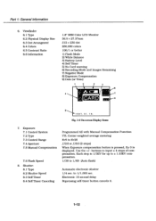
... 0 Light Sensor (Flash) 0 Self-timer Lamp O Flash O DC-IN Terminal 6V 9 ® Digital Terminal 0 Video Out Terminal O Lens 8 ▪ CF Card Slot O Battery Chamber Release Lever 7 9 0 0 O Flash Button 8 Self-timer Button • + & - Adjustment Buttons 3 +/- (Exposure Comp.) Button O W. Button ▪ Image Quality Switch ▪ Brightness Adjustment Nig ® REC/...
... 0 Light Sensor (Flash) 0 Self-timer Lamp O Flash O DC-IN Terminal 6V 9 ® Digital Terminal 0 Video Out Terminal O Lens 8 ▪ CF Card Slot O Battery Chamber Release Lever 7 9 0 0 O Flash Button 8 Self-timer Button • + & - Adjustment Buttons 3 +/- (Exposure Comp.) Button O W. Button ▪ Image Quality Switch ▪ Brightness Adjustment Nig ® REC/...

Service Manual
Page 16
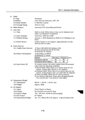
... power, the power supply shuts off under the following conditions: 1) Record Mode: When there is no switch input for two minutes. (Using battery only- not valid with open memory, set the Record mode and turn on the power switch. Depending on the content. The Busy/Power lamp...go off only after the sequence is finished. • During the sequence all indications on the LCD go off approximately five seconds after "Low Battery" mark starts flashing. The "Remaining Image" counter indication is displayed for the next shot. Recording Mode File Size Exposu res/Card(M in.) Economy...
... power, the power supply shuts off under the following conditions: 1) Record Mode: When there is no switch input for two minutes. (Using battery only- not valid with open memory, set the Record mode and turn on the power switch. Depending on the content. The Busy/Power lamp...go off only after the sequence is finished. • During the sequence all indications on the LCD go off approximately five seconds after "Low Battery" mark starts flashing. The "Remaining Image" counter indication is displayed for the next shot. Recording Mode File Size Exposu res/Card(M in.) Economy...
Service Manual
Page 20
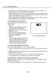
... displayed during ALLERASE, the power will turn of automatically regardless of th condition of the erasure process. 2.12 LOW BATTERY INDICATOR The two-step battery indicator monitors the battery voltage. 1. or if the card is removed with the power on. • In Record mode, the mark...8226; During the erasure, ALLERASE will be cancelled by with a PC, all switches except the Power switch are disabled. 1-10 Fig. 1-5 Low Battery Indication 2.13 CF CARD WARNING INDICATOR Under the following conditions, the -G-irro mark is complete, the screen will flash at 1Hz. If a damaged card...
... displayed during ALLERASE, the power will turn of automatically regardless of th condition of the erasure process. 2.12 LOW BATTERY INDICATOR The two-step battery indicator monitors the battery voltage. 1. or if the card is removed with the power on. • In Record mode, the mark...8226; During the erasure, ALLERASE will be cancelled by with a PC, all switches except the Power switch are disabled. 1-10 Fig. 1-5 Low Battery Indication 2.13 CF CARD WARNING INDICATOR Under the following conditions, the -G-irro mark is complete, the screen will flash at 1Hz. If a damaged card...
Service Manual
Page 22
... Arrangment 6.4 Colors 6.5 Contrast Ratio 6.6 Information 1.8" MIM Color LCD Monitor 36.5 x 27.37mm 312 x 230 dot 260,000 colors 100/1 or better 1) Flash Mode 2) White Balance 3) Battery Level 4) Self Timer 5) No Card warning 6) Recording Mode and Images Remaining 7) Negative Mode 8) Exposure Compensation 9) Date (or Time) 1 2 7 E- 0 9 1 9 9 7. 01. 16. Exposure 7.1 Control System 7.2 Type 7.3 Control...
... Arrangment 6.4 Colors 6.5 Contrast Ratio 6.6 Information 1.8" MIM Color LCD Monitor 36.5 x 27.37mm 312 x 230 dot 260,000 colors 100/1 or better 1) Flash Mode 2) White Balance 3) Battery Level 4) Self Timer 5) No Card warning 6) Recording Mode and Images Remaining 7) Negative Mode 8) Exposure Compensation 9) Date (or Time) 1 2 7 E- 0 9 1 9 9 7. 01. 16. Exposure 7.1 Control System 7.2 Type 7.3 Control...
Service Manual
Page 23
...Three LR6 (AM3/AA) Alkaline Cells 2) Three special AA size Ni-Cd Cells 3) Exclusive AC Adaptor 1) Recording: 4.2 Watts 2) Playback: 2.7 Watts Battery Recording Panasonic LR6 (G) 30 Panasonic NiCd P-3GAV 55 Playback (min.) 60 85 To conserve power, the power supply shuts off approximately five seconds after ..."Low Battery" mark lights. (W) 94 x (H) 96 x (D) 53 mm Approx. 280g Direct Plug In to 3.0m Automatic (ITL Auto) (Manual (Preset)...
...Three LR6 (AM3/AA) Alkaline Cells 2) Three special AA size Ni-Cd Cells 3) Exclusive AC Adaptor 1) Recording: 4.2 Watts 2) Playback: 2.7 Watts Battery Recording Panasonic LR6 (G) 30 Panasonic NiCd P-3GAV 55 Playback (min.) 60 85 To conserve power, the power supply shuts off approximately five seconds after ..."Low Battery" mark lights. (W) 94 x (H) 96 x (D) 53 mm Approx. 280g Direct Plug In to 3.0m Automatic (ITL Auto) (Manual (Preset)...
Service Manual
Page 24
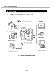
Part 1: General Information 4. SYSTEM 4.1 SYSTEM COMPONENTS AND ANCILLARIES
Part 1: General Information 4. SYSTEM 4.1 SYSTEM COMPONENTS AND ANCILLARIES
Service Manual
Page 25
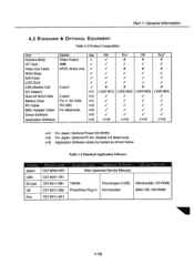
... Cloth / / V V V LR6 Alkaline Cell 3 each / X X X X AC Adaptor 400 /(AD-901) t/(AD-902) ti(AD-903) /(AD-904) Size AA NiCd Cells 3 each AC) i si i ti Battery Case For 3 AA Cells 430 V / / ,/ PC Cable IFC-35D 42 i i i / MAC Adapter Cable For Macintosh 0D© ./ ,/ i i Driver Software ita® t/ ./ V / Application Software 162 /op...
... Cloth / / V V V LR6 Alkaline Cell 3 each / X X X X AC Adaptor 400 /(AD-901) t/(AD-902) ti(AD-903) /(AD-904) Size AA NiCd Cells 3 each AC) i si i ti Battery Case For 3 AA Cells 430 V / / ,/ PC Cable IFC-35D 42 i i i / MAC Adapter Cable For Macintosh 0D© ./ ,/ i i Driver Software ita® t/ ./ V / Application Software 162 /op...
Service Manual
Page 33
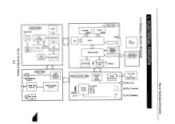
... Charge Circuit elf Time LED C Main CBA D-RAM (4Mbit) FIFO (1Mbit) ND ASIC 50pin RISC-µCOM Battery Voltage Detedt EEPROM -7 CLOCK (Date) 32KHz CF CARD Operation SW CBA ower/Interface CB VIDEO OUT Circuit Battery LR6 x3 Power Circuit UNREG. 18V 5V 3.3V -8V -25V RGB Converter 1.8" LCD Back Light 0 VIDEO...
... Charge Circuit elf Time LED C Main CBA D-RAM (4Mbit) FIFO (1Mbit) ND ASIC 50pin RISC-µCOM Battery Voltage Detedt EEPROM -7 CLOCK (Date) 32KHz CF CARD Operation SW CBA ower/Interface CB VIDEO OUT Circuit Battery LR6 x3 Power Circuit UNREG. 18V 5V 3.3V -8V -25V RGB Converter 1.8" LCD Back Light 0 VIDEO...
Service Manual
Page 40
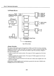
...® IS1002 is used for the monitor section The output of the battery passes through three transformers (T1001, 1002, and 1003) and rectifiers to give the necessary voltages to drive the PowerShot 350. T1003 DC 6V From AC Adapter IC3006 (Date/Time) 0. Additionally,... IC3006 supplies power (and back-up power) for the flash. Part 2: Technical Information 1.8 POWER BLOCK F2201 F1001 Battery 31Charge H IC2002 411 SW 5V 5 IC1001 5 IC1002 5...
...® IS1002 is used for the monitor section The output of the battery passes through three transformers (T1001, 1002, and 1003) and rectifiers to give the necessary voltages to drive the PowerShot 350. T1003 DC 6V From AC Adapter IC3006 (Date/Time) 0. Additionally,... IC3006 supplies power (and back-up power) for the flash. Part 2: Technical Information 1.8 POWER BLOCK F2201 F1001 Battery 31Charge H IC2002 411 SW 5V 5 IC1001 5 IC1002 5...
Service Manual
Page 51
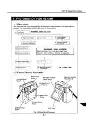
HIGH VOLTAGE When removing Front Cover don't touch Flash Capacitor terminals before bleeding the capacitor. 9] Battery Circuit Board 111 LCD Panel 10] Battery Cover 12] Backlight Interface Circuit Board 1.2 CIRCUIT BOARD PLACEMENT Camera Circuit Board Flash Circuit Board Backlight...Fig. 3-1 Flow Chart Operation Switchs Circuit Board VJ 41 0 It e Main Circuit / 41" Board II • Shutter Circuit Board Battery Circuit Board LCD Panel Fig. 3-2 Circuit Board Placement 3-1 PREPARATION FOR REPAIR 1.1 PROCEDURE The following flow chart describes the disassembly steps necessary...
HIGH VOLTAGE When removing Front Cover don't touch Flash Capacitor terminals before bleeding the capacitor. 9] Battery Circuit Board 111 LCD Panel 10] Battery Cover 12] Backlight Interface Circuit Board 1.2 CIRCUIT BOARD PLACEMENT Camera Circuit Board Flash Circuit Board Backlight...Fig. 3-1 Flow Chart Operation Switchs Circuit Board VJ 41 0 It e Main Circuit / 41" Board II • Shutter Circuit Board Battery Circuit Board LCD Panel Fig. 3-2 Circuit Board Placement 3-1 PREPARATION FOR REPAIR 1.1 PROCEDURE The following flow chart describes the disassembly steps necessary...
Service Manual
Page 52
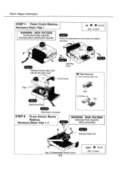
...; , 4 (SILVER) M2 x 2.4mm WARNING - Pull flex out. Clips Tabs 2. HIGH VOLTAGE Discharge Flash Capacitor before bleeding the capacitor Press the opening lever and open the battery chamber. .*N9 0X3 Step 2 Step 4 Release the two clips, and remove the front cover Opening Lever Front Cover J Flex Removal 1.
...; , 4 (SILVER) M2 x 2.4mm WARNING - Pull flex out. Clips Tabs 2. HIGH VOLTAGE Discharge Flash Capacitor before bleeding the capacitor Press the opening lever and open the battery chamber. .*N9 0X3 Step 2 Step 4 Release the two clips, and remove the front cover Opening Lever Front Cover J Flex Removal 1.
Service Manual
Page 55
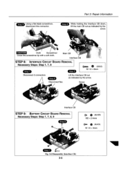
... REMOVAL Necessary Steps: Step 1, 7, 8 Step 1 Step 3 (GOLD) M 1.6 x 8mm Disconnect 2 connectors Step 2 Lift the Interface CB out as indicated by the arrow. Screw , Interface CB STEP 9: BATTERY CIRCUIT BOARD REMOVAL Necessary Steps: Step 1, 7, 8, 9 Step 2 0.. Part 3: Repair Information Step 5 While holding the Interface CB down, lift the main CB out as indicated by...
... REMOVAL Necessary Steps: Step 1, 7, 8 Step 1 Step 3 (GOLD) M 1.6 x 8mm Disconnect 2 connectors Step 2 Lift the Interface CB out as indicated by the arrow. Screw , Interface CB STEP 9: BATTERY CIRCUIT BOARD REMOVAL Necessary Steps: Step 1, 7, 8, 9 Step 2 0.. Part 3: Repair Information Step 5 While holding the Interface CB down, lift the main CB out as indicated by...
Service Manual
Page 56
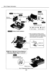
... Tripod Socke Step Remove Left Chassis Plate it step 7 QX 2 a CAUTION Battery Holder Installation Step 8 Step 5 Remove Battery CB e ) (BLACK) M 1.4 x3mm e (BLACK) M 1.6 x 4mm • When reinstalling the Battery Holder, insure that the arms on the three switches correctly couple with the switch... should be in the up position. 4 Switch Knob STEP 10: BATTERY COVER REMOVAL Necessary Steps: Step 1, 7, 8, 9, 10 Step 1 Unlock the claw, and remove the Battery Cover. Claw t. Battery Cove Fig. 3-7 Disassembly (Battery Cover) 3-6 Switch arm Switch Knob Part 3: Repair Information Step 3...
... Tripod Socke Step Remove Left Chassis Plate it step 7 QX 2 a CAUTION Battery Holder Installation Step 8 Step 5 Remove Battery CB e ) (BLACK) M 1.4 x3mm e (BLACK) M 1.6 x 4mm • When reinstalling the Battery Holder, insure that the arms on the three switches correctly couple with the switch... should be in the up position. 4 Switch Knob STEP 10: BATTERY COVER REMOVAL Necessary Steps: Step 1, 7, 8, 9, 10 Step 1 Unlock the claw, and remove the Battery Cover. Claw t. Battery Cove Fig. 3-7 Disassembly (Battery Cover) 3-6 Switch arm Switch Knob Part 3: Repair Information Step 3...
Service Manual
Page 58
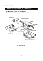
O LCD Unit Interface CBA Ass'y Front Cover Unit Main CBA Ass'y CY9-9512-000 eo CY9-9513-000 I 0 0 00 Rear Cover Unit w/Battery Case Fig. 3-9 Extension Cables 3-8 Camera Unit 0 CY9-9514-000 Operation Switch CBA 0 00,00 CY9-9511-000 O,. PREPARATIONS FOR ADJUSTMENTS 2.1 EXTENSION CABLES FOR UNIT CHECKS The extension cables shown are available for circuit checking with an open camera. Part 3: Repair information 2.
O LCD Unit Interface CBA Ass'y Front Cover Unit Main CBA Ass'y CY9-9512-000 eo CY9-9513-000 I 0 0 00 Rear Cover Unit w/Battery Case Fig. 3-9 Extension Cables 3-8 Camera Unit 0 CY9-9514-000 Operation Switch CBA 0 00,00 CY9-9511-000 O,. PREPARATIONS FOR ADJUSTMENTS 2.1 EXTENSION CABLES FOR UNIT CHECKS The extension cables shown are available for circuit checking with an open camera. Part 3: Repair information 2.
Service Manual
Page 103
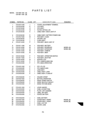
... ASS'Y N 1 FILTER, OPTICAL (IR) E 1 CABLE ASS'Y, BACK LIGHT l/F E 1 CABLE ASS'Y, BATTERY-POWER CBA M 1 PCB ASS'Y, FLASH J 1 HOLDER, LED L 1 FLASH ASS'Y P 1 PCB ASS'Y, BACK LIGHT I/F M 1 PCB ASS'Y, BATTERY M 1 PCB ASS'Y, INTERFACE M 1 PCB ASS'Y, INTERFACE M 1 PCB ASS'Y, CAMERA M 1 PCB ASS..., PICTURE MODE F 1 LEVER, MACRO J 1 CASE, LCD BOTTOM N 1 PLATE, LEFT CHASSIS J 1 LABEL, BATTERY J 1 COVER, BATTERY J 1 CASE, BATTERY J 1 COVER ASS'Y, FRONT J 1 COVER ASS'Y, FRONT J 1 CASE, LCD TOP J 1 COVER, LENS REMARKS MODEL [A] MODEL [B] MODEL [A] MODEL [B] P3
... ASS'Y N 1 FILTER, OPTICAL (IR) E 1 CABLE ASS'Y, BACK LIGHT l/F E 1 CABLE ASS'Y, BATTERY-POWER CBA M 1 PCB ASS'Y, FLASH J 1 HOLDER, LED L 1 FLASH ASS'Y P 1 PCB ASS'Y, BACK LIGHT I/F M 1 PCB ASS'Y, BATTERY M 1 PCB ASS'Y, INTERFACE M 1 PCB ASS'Y, INTERFACE M 1 PCB ASS'Y, CAMERA M 1 PCB ASS..., PICTURE MODE F 1 LEVER, MACRO J 1 CASE, LCD BOTTOM N 1 PLATE, LEFT CHASSIS J 1 LABEL, BATTERY J 1 COVER, BATTERY J 1 CASE, BATTERY J 1 COVER ASS'Y, FRONT J 1 COVER ASS'Y, FRONT J 1 CASE, LCD TOP J 1 COVER, LENS REMARKS MODEL [A] MODEL [B] MODEL [A] MODEL [B] P3
Service Manual
Page 125
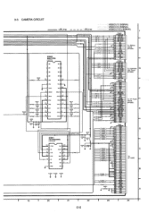
... INPACK - 3-3. g8 P1 ) P3 P3 sv) I 24 E15 A 29 GND GND DA C 30 GND RRSTID)- TrEn- 45 BVD2 STSCHG g DO8 DO9 49 D1O GND To Battery Circuit (PP2201) To Operation SW Circuit (PP2001) To VF Power Circuit (PP8001) To CF CARD 19 I 20 I 21 I 22 I 23 I PS3OO1 V S3955CO18 PWR SW 2 KEY...
... INPACK - 3-3. g8 P1 ) P3 P3 sv) I 24 E15 A 29 GND GND DA C 30 GND RRSTID)- TrEn- 45 BVD2 STSCHG g DO8 DO9 49 D1O GND To Battery Circuit (PP2201) To Operation SW Circuit (PP2001) To VF Power Circuit (PP8001) To CF CARD 19 I 20 I 21 I 22 I 23 I PS3OO1 V S3955CO18 PWR SW 2 KEY...

Service Manual
Page 128
... 10V4R7 OR501 0503 J2302 J2301 50 To Main Precess Circuit (FP3003 FP501 o. age. trical shock and H ® Always disconnect the AC adaptor and remove the battery before WARNING changing any parts. G 3-4. ADJ. 2 ENSOR) UN5217 (SWITCHING /STR.TRI.) R5051 5V R562 IC551 UPC393G2 I C552 C551 0.1 0.1 8561 R560 27K > 47K C554 4700 (COMPARATOR...
... 10V4R7 OR501 0503 J2302 J2301 50 To Main Precess Circuit (FP3003 FP501 o. age. trical shock and H ® Always disconnect the AC adaptor and remove the battery before WARNING changing any parts. G 3-4. ADJ. 2 ENSOR) UN5217 (SWITCHING /STR.TRI.) R5051 5V R562 IC551 UPC393G2 I C552 C551 0.1 0.1 8561 R560 27K > 47K C554 4700 (COMPARATOR...
Service Manual
Page 129
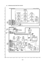
...(POWER) (PICTURE OUALITY) (PLAY/REC) D S2201 VSS0533 52202 VS50535 52203 V550534 ON/OFF ...- DET.) 2 3 0 0.1 R2209 470 D2203 MA133 2 R2, OPERATION CIRCUIT/BATTERY CIRCUIT OPERATION CIRCUIT (WHITE BALANCE) S2001 VSP1035 2 3 :+B Line (NEGA.POJI/SCREEN MODE) 52002 VSP1035 (DATE) S2003 VSP1035 (DISPLAY) S2004 VSP1035 H 2 2 3 ...MO28 (DELETE) 02007 VSP1035 2 3 (FLASH S2010 VSP)1035 2 3 gA27238 (REC/PLAY) 02004 1N107W5PRW 2 4 RR 02 01 03 TT BATTERY CIRCUIT To Main Process Circuit (J1) E P2201 VJP3954C005 To VP Power Cirouit (P8001) TT BAIT 2 AC A 3 5V 4 LCD VR...
...(POWER) (PICTURE OUALITY) (PLAY/REC) D S2201 VSS0533 52202 VS50535 52203 V550534 ON/OFF ...- DET.) 2 3 0 0.1 R2209 470 D2203 MA133 2 R2, OPERATION CIRCUIT/BATTERY CIRCUIT OPERATION CIRCUIT (WHITE BALANCE) S2001 VSP1035 2 3 :+B Line (NEGA.POJI/SCREEN MODE) 52002 VSP1035 (DATE) S2003 VSP1035 (DISPLAY) S2004 VSP1035 H 2 2 3 ...MO28 (DELETE) 02007 VSP1035 2 3 (FLASH S2010 VSP)1035 2 3 gA27238 (REC/PLAY) 02004 1N107W5PRW 2 4 RR 02 01 03 TT BATTERY CIRCUIT To Main Process Circuit (J1) E P2201 VJP3954C005 To VP Power Cirouit (P8001) TT BAIT 2 AC A 3 5V 4 LCD VR...


