Service Manual
Page 5
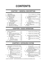
... Assembly...3-11 A. Turning the Scanning Lamp COPYRIGHT © 1998 CANON INC. Cross Section 1-5 IV. Outline 2-1 B. Basic Sequence of Exposure System ...3-1 Scanning Lamp 3-8 B. Operation 2-5 3. Inputs to Replace the Cartridge 1-11 2. Inputs to DC Controller (1/2 2-6 2. Outputs from DC Controller ....2-8 1. Outline of Operations (A4, 2 copies 2-3 D. Copyboard Drive System........3-1 C. Outline 3-7 1. CANON PC400/420/430,FC200/220 REV.0 JAN.1998 PRINTED...
... Assembly...3-11 A. Turning the Scanning Lamp COPYRIGHT © 1998 CANON INC. Cross Section 1-5 IV. Outline 2-1 B. Basic Sequence of Exposure System ...3-1 Scanning Lamp 3-8 B. Operation 2-5 3. Inputs to Replace the Cartridge 1-11 2. Inputs to DC Controller (1/2 2-6 2. Outputs from DC Controller ....2-8 1. Outline of Operations (A4, 2 copies 2-3 D. Copyboard Drive System........3-1 C. Outline 3-7 1. CANON PC400/420/430,FC200/220 REV.0 JAN.1998 PRINTED...

Service Manual
Page 14
...; Copying on each side no more than three times. A4/LTR, 80 g/m2) Auto power-off Available (5 min, approx.) *PC430 only. 1-2 COPYRIGHT © 1998 CANON INC. A4R/LTR-R 4 copies/min (A4R/LTR-R or or smaller) smaller) 3 copies/min (LGL) Performance Copy size Copy... Photosensitive medium Copying Charging Exposure Copy density adjustment Development Pick-up Separation Cleaning Fixing Document type Maximum document size Reproduction ratio Wait time First copy Continuous copying Copying speed PC400/FC200 PC420/430/FC220 Portable (w/ grips) Moving Tungsten lamp of A4, 80 g/...
...; Copying on each side no more than three times. A4/LTR, 80 g/m2) Auto power-off Available (5 min, approx.) *PC430 only. 1-2 COPYRIGHT © 1998 CANON INC. A4R/LTR-R 4 copies/min (A4R/LTR-R or or smaller) smaller) 3 copies/min (LGL) Performance Copy size Copy... Photosensitive medium Copying Charging Exposure Copy density adjustment Development Pick-up Separation Cleaning Fixing Document type Maximum document size Reproduction ratio Wait time First copy Continuous copying Copying speed PC400/FC200 PC420/430/FC220 Portable (w/ grips) Moving Tungsten lamp of A4, 80 g/...

Service Manual
Page 29
...lamp Primary charging roller Lens array Developing blade Fixing film Cleaning blade Photosensitive drum Developing cylinder Pressure roller Transfer charging roller Static eliminator Figure 1-501A The copier is an indirect photorepro graphic system constructed as discussed below. Image exposure Step 1 : Primary charging (negative) Step 2 : Image exposure... Registration Multifeeder : Flow of copy paper : Rotation of seven steps as shown in Figure 1-501A. CANON PC400/420/430,FC200/220 REV.0 JAN.1998 PRINTED IN JAPAN (IMPRIME AU JAPON) 1-17 Primary charging 2. Drum ...
...lamp Primary charging roller Lens array Developing blade Fixing film Cleaning blade Photosensitive drum Developing cylinder Pressure roller Transfer charging roller Static eliminator Figure 1-501A The copier is an indirect photorepro graphic system constructed as discussed below. Image exposure Step 1 : Primary charging (negative) Step 2 : Image exposure... Registration Multifeeder : Flow of copy paper : Rotation of seven steps as shown in Figure 1-501A. CANON PC400/420/430,FC200/220 REV.0 JAN.1998 PRINTED IN JAPAN (IMPRIME AU JAPON) 1-17 Primary charging 2. Drum ...

Service Manual
Page 43
... SYSTEM 3-1 A. Operations 3-8 C. Outline of the Scanning Lamp (VR604) ........3-8 III. CANON PC400/420/430,FC200/220 REV.0 JAN.1998 PRINTED IN JAPAN (IMPRIME AU JAPON) 1 Controlling the Intensity of Exposure System ...3-1 B. Outline 3-7 B. MECHANICAL SYSTEM 3-9 A. I. CHAPTER 3 EXPOSURE SYSTEM This chapter outlines the machine's copyboard drive and scanning lamp control systems in relation to mechanisms and functions, relationship between...
... SYSTEM 3-1 A. Operations 3-8 C. Outline of the Scanning Lamp (VR604) ........3-8 III. CANON PC400/420/430,FC200/220 REV.0 JAN.1998 PRINTED IN JAPAN (IMPRIME AU JAPON) 1 Controlling the Intensity of Exposure System ...3-1 B. Outline 3-7 B. MECHANICAL SYSTEM 3-9 A. I. CHAPTER 3 EXPOSURE SYSTEM This chapter outlines the machine's copyboard drive and scanning lamp control systems in relation to mechanisms and functions, relationship between...

Service Manual
Page 45
... Stop Copier Continuous copying Figure 3-101B Front View COPYRIGHT © 1998 CANON INC. Outline of Exposure System While the copyboard is moving forward, the scanning lamp (LA1 through the lens array. Copyboard glass Scanning lamp Lens array Photosensitive drum Figure 3-101A B. CANON PC400/420/430,FC200/220 REV.0 JAN.1998 PRINTED IN JAPAN (IMPRIME AU JAPON...
... Stop Copier Continuous copying Figure 3-101B Front View COPYRIGHT © 1998 CANON INC. Outline of Exposure System While the copyboard is moving forward, the scanning lamp (LA1 through the lens array. Copyboard glass Scanning lamp Lens array Photosensitive drum Figure 3-101A B. CANON PC400/420/430,FC200/220 REV.0 JAN.1998 PRINTED IN JAPAN (IMPRIME AU JAPON...

Service Manual
Page 46
.... CANON PC400/420/430,FC200/220 REV.0 JAN.1998 PRINTED IN JAPAN (IMPRIME AU JAPON) Copyboard position (cams) Reversal cam Registration cam Start position cam Reverse Copyboard position sensor lever Copyboard position sensor (Q902): OFF (front view) • Copyboard is at the start position. • Copyboard drive solenoid goes OFF. • Scanning lamp...
.... CANON PC400/420/430,FC200/220 REV.0 JAN.1998 PRINTED IN JAPAN (IMPRIME AU JAPON) Copyboard position (cams) Reversal cam Registration cam Start position cam Reverse Copyboard position sensor lever Copyboard position sensor (Q902): OFF (front view) • Copyboard is at the start position. • Copyboard drive solenoid goes OFF. • Scanning lamp...

Service Manual
Page 51
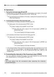
...prevent rush current occurring when the lamp turns on. CHAPTER 3 EXPOSURE SYSTEM II. Controlling the Scanning Lamp A. In addition, a rush current protection circuit is provided to ensure that the original will be illuminated after the intensity of the scanning lamp. Outline Figure 3-201A shows ...is provided to make sure that controls the scanning lamp (fuse lamp), and the circuit has the following functions: • Turns the scanning lamp ON and OFF. • Controls the intensity of the scanning lamp has stabilized. CANON PC400/420/430,FC200/220 REV.0 JAN.1998 PRINTED IN JAPAN (...
...prevent rush current occurring when the lamp turns on. CHAPTER 3 EXPOSURE SYSTEM II. Controlling the Scanning Lamp A. In addition, a rush current protection circuit is provided to ensure that the original will be illuminated after the intensity of the scanning lamp. Outline Figure 3-201A shows ...is provided to make sure that controls the scanning lamp (fuse lamp), and the circuit has the following functions: • Turns the scanning lamp ON and OFF. • Controls the intensity of the scanning lamp has stabilized. CANON PC400/420/430,FC200/220 REV.0 JAN.1998 PRINTED IN JAPAN (...
Service Manual
Page 52
... amplifi er circuit are indicated by 'E6' for the PC420/430/FC220 and 'JAM' for 2 min at high frequency. 2. CHAPTER 3 EXPOSURE SYSTEM B. Current flowing to the output of the lamp if you have replaced the scanning lamp unit, intensity sensor or control panel PCB; see p.10-6. ...LAPWM command corresponding to the lamp increases. • If the intensity of the lamp is high when the lamp goes ON, Initial power of the Scanning Lamp (VR604) You must adjust the AE mechanism after adjusting the intensity. (PC420/430/FC220) 3-8 COPYRIGHT © 1998 CANON INC. Controlling the Intensity...
... amplifi er circuit are indicated by 'E6' for the PC420/430/FC220 and 'JAM' for 2 min at high frequency. 2. CHAPTER 3 EXPOSURE SYSTEM B. Current flowing to the output of the lamp if you have replaced the scanning lamp unit, intensity sensor or control panel PCB; see p.10-6. ...LAPWM command corresponding to the lamp increases. • If the intensity of the lamp is high when the lamp goes ON, Initial power of the Scanning Lamp (VR604) You must adjust the AE mechanism after adjusting the intensity. (PC420/430/FC220) 3-8 COPYRIGHT © 1998 CANON INC. Controlling the Intensity...
Service Manual
Page 54
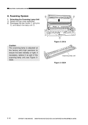
Caution: The scanning lamp is adjusted at the factory with high precision to ensure the best intensity of the scanning lamp unit; if necessary, replace it as part of light; Scanning System disengage 1. see Figure 3302A. Œ Figure 3-301A Scanning lamp unit Figure 3-302A 3-10 COPYRIGHT © 1998 CANON INC. CHAPTER 3 EXPOSURE SYSTEM A. CANON PC400/420/430,FC200/220 REV.0 JAN.1998 PRINTED IN JAPAN (IMPRIME AU JAPON) Detaching the Scanning Lamp Unit 1) Detach the top cover assembly. 2) Disengage the two hooks q and pins w, and detach the lamp unit e.
Caution: The scanning lamp is adjusted at the factory with high precision to ensure the best intensity of the scanning lamp unit; if necessary, replace it as part of light; Scanning System disengage 1. see Figure 3302A. Œ Figure 3-301A Scanning lamp unit Figure 3-302A 3-10 COPYRIGHT © 1998 CANON INC. CHAPTER 3 EXPOSURE SYSTEM A. CANON PC400/420/430,FC200/220 REV.0 JAN.1998 PRINTED IN JAPAN (IMPRIME AU JAPON) Detaching the Scanning Lamp Unit 1) Detach the top cover assembly. 2) Disengage the two hooks q and pins w, and detach the lamp unit e.


