Service Manual
Page 4
...power" means flipping on the power switch, closing the front door, and closing the delivery unit door, which results in the machine. CANON PC400/420/430,FC200/220 REV.0 JAN.1998 PRINTED IN JAPAN (IMPRIME AU JAPON) In the digital circuits, '1' is used to indicate that the ...circuit.) In practically all relevant Service Information bulletins and be able to identify and isolate faults in supplying the machine with reference to the timing of the electric signal. ii COPYRIGHT © 1998 CANON INC. Note: The descriptions in this Service Manual: 1. In the diagrams, represents the path ...
...power" means flipping on the power switch, closing the front door, and closing the delivery unit door, which results in the machine. CANON PC400/420/430,FC200/220 REV.0 JAN.1998 PRINTED IN JAPAN (IMPRIME AU JAPON) In the digital circuits, '1' is used to indicate that the ...circuit.) In practically all relevant Service Information bulletins and be able to identify and isolate faults in supplying the machine with reference to the timing of the electric signal. ii COPYRIGHT © 1998 CANON INC. Note: The descriptions in this Service Manual: 1. In the diagrams, represents the path ...
Service Manual
Page 6
...Supply Power to the Fixing Heater 6-3 D. Outline 4-6 2. PC420/430/FC220).......4-14 1. Cleaning the Drum...........4-19 B. OUTLINE 5-1 II. PC420/430/FC220 5-2 B. CONTROLLING THE REGISTRATION ROLLER...........5-4 A. Pick-Up Delay Jam (PC420/430/FC220 5-8 D. MECHANICAL SYSTEM............5-10 A. Detaching the Registration Roller Assembly 5-14 C. Fixing Assembly 6-7 iv COPYRIGHT © 1998 CANON... Formation Operations (A4, 2 copies) .......4-2 C. Registration Roller Assembly 5-14 1. CANON PC400/420/430,FC200/220 REV.0 JAN.1998 PRINTED IN JAPAN (IMPRIME AU JAPON) CHAPTER ...
...Supply Power to the Fixing Heater 6-3 D. Outline 4-6 2. PC420/430/FC220).......4-14 1. Cleaning the Drum...........4-19 B. OUTLINE 5-1 II. PC420/430/FC220 5-2 B. CONTROLLING THE REGISTRATION ROLLER...........5-4 A. Pick-Up Delay Jam (PC420/430/FC220 5-8 D. MECHANICAL SYSTEM............5-10 A. Detaching the Registration Roller Assembly 5-14 C. Fixing Assembly 6-7 iv COPYRIGHT © 1998 CANON... Formation Operations (A4, 2 copies) .......4-2 C. Registration Roller Assembly 5-14 1. CANON PC400/420/430,FC200/220 REV.0 JAN.1998 PRINTED IN JAPAN (IMPRIME AU JAPON) CHAPTER ...
Service Manual
Page 7
...Cartridges.......9-2 B. Image Adjustment Basic 1. Procedure 10-3 Image Width (position of glass).....10-5 II. STANDARDS AND 2. Power Supply PCB 7-2 C. Detaching the Body Cover 7-5 3. Detaching the DC Controller/DC Power Supply PCB 7-11 2. Storing and Handling Unsealed Cartridges 9-3 1. External Covers 7-4 1. PERIODICALLY REPLACED PARTS 9-1 II. MAINTENANCE...8-2 III. DURABLES 9-1 III. Image Leading Edge Non- Image Leading Edge Margin COPYRIGHT © 1998 CANON INC. CANON PC400/420/430,FC200/220 REV.0 JAN.1998 PRINTED IN JAPAN (IMPRIME AU JAPON) v
...Cartridges.......9-2 B. Image Adjustment Basic 1. Procedure 10-3 Image Width (position of glass).....10-5 II. STANDARDS AND 2. Power Supply PCB 7-2 C. Detaching the Body Cover 7-5 3. Detaching the DC Controller/DC Power Supply PCB 7-11 2. Storing and Handling Unsealed Cartridges 9-3 1. External Covers 7-4 1. PERIODICALLY REPLACED PARTS 9-1 II. MAINTENANCE...8-2 III. DURABLES 9-1 III. Image Leading Edge Non- Image Leading Edge Margin COPYRIGHT © 1998 CANON INC. CANON PC400/420/430,FC200/220 REV.0 JAN.1998 PRINTED IN JAPAN (IMPRIME AU JAPON) v

Service Manual
Page 9
... ELECTRICAL PARTS ........10-34 A. Switches 10-35 C. SOLVENTS/OILS TABLE A-8 COPYRIGHT © 1998 CANON INC. Lamp, Heater, Motor, and Others 10-36 D. DC Controller/DC Power Supply PCB 10-38 2. SELF DIAGNOSIS 10-40 APPENDIX A. Signals A-3 2. Abbreviations A-4 C. CANON PC400/420/430,FC200/220 REV.0 JAN.1998 PRINTED IN JAPAN (IMPRIME AU JAPON) vii Wrinkles...
... ELECTRICAL PARTS ........10-34 A. Switches 10-35 C. SOLVENTS/OILS TABLE A-8 COPYRIGHT © 1998 CANON INC. Lamp, Heater, Motor, and Others 10-36 D. DC Controller/DC Power Supply PCB 10-38 2. SELF DIAGNOSIS 10-40 APPENDIX A. Signals A-3 2. Abbreviations A-4 C. CANON PC400/420/430,FC200/220 REV.0 JAN.1998 PRINTED IN JAPAN (IMPRIME AU JAPON) vii Wrinkles...

Service Manual
Page 15
See CHAPTER 9. CANON PC400/420/430,FC200/220 REV.0 JAN.1998 PRINTED IN JAPAN (IMPRIME AU JAPON) 1-3 CHAPTER 1 GENERAL DESCRIPTION Item PC400/FC200 PC420/430/FC220 Temperature 7.5° to 32.5°C/45.5° to 90.5°F Operating Humidity environment 5% to 85% ...Height 4.1 in./108 mm Weight (including cartridge) 16.6 lb/7.4 kg (approx.) Copy paper Consumables Cartridge Keep wrapped to 1 atm) 120V, 60Hz Power supply Serial numbers ZTG !!!!! (PC400:WHITE) ZTH !!!!! (PC400:GRAY) Serial numbers NVD !!!!! (FC220:WHITE) ZTJ !!!!! (PC420:WHITE) 230V, 50Hz RTL/PTQ...
See CHAPTER 9. CANON PC400/420/430,FC200/220 REV.0 JAN.1998 PRINTED IN JAPAN (IMPRIME AU JAPON) 1-3 CHAPTER 1 GENERAL DESCRIPTION Item PC400/FC200 PC420/430/FC220 Temperature 7.5° to 32.5°C/45.5° to 90.5°F Operating Humidity environment 5% to 85% ...Height 4.1 in./108 mm Weight (including cartridge) 16.6 lb/7.4 kg (approx.) Copy paper Consumables Cartridge Keep wrapped to 1 atm) 120V, 60Hz Power supply Serial numbers ZTG !!!!! (PC400:WHITE) ZTH !!!!! (PC400:GRAY) Serial numbers NVD !!!!! (FC220:WHITE) ZTJ !!!!! (PC420:WHITE) 230V, 50Hz RTL/PTQ...

Service Manual
Page 18
... darker, bottom for each copy made . • ' ' is displayed to an error found by varying the developing bias. 1-6 COPYRIGHT © 1998 CANON INC. r Jam Indicator • Flashes when paper jams inside the copier. Control Panel 1. t Copy Count Indicator • Displays the number of paper... copying, the key serves as a Clear key, setting the copy count to select/deselect AE (automatic exposure) mode. PC420/430/FC220 3 654 AE A Error indications : Check jam/Supply paper : Jam and : Check error and : Check error and : Check error C ON OFF 9 darker lighter lighter darker...
... darker, bottom for each copy made . • ' ' is displayed to an error found by varying the developing bias. 1-6 COPYRIGHT © 1998 CANON INC. r Jam Indicator • Flashes when paper jams inside the copier. Control Panel 1. t Copy Count Indicator • Displays the number of paper... copying, the key serves as a Clear key, setting the copy count to select/deselect AE (automatic exposure) mode. PC420/430/FC220 3 654 AE A Error indications : Check jam/Supply paper : Jam and : Check error and : Check error and : Check error C ON OFF 9 darker lighter lighter darker...
Service Manual
Page 34
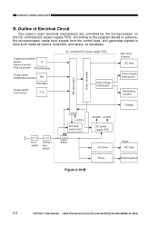
...roller Developing cylinder Q101 +DC5V Sub power supply circuit +DC24V +DC5V DC power supply PCB Display Door switch Delivery door switch Relay AC driver Driver Heater AC load Scanning lamp Figure 2-101B 2-2 COPYRIGHT © 1998 CANON INC. CANON PC400/420/430,FC200/220 REV.0 JAN.1998 PRINTED IN... JAPAN (IMPRIME AU JAPON) Outline of Electrical Circuit The copier's main electrical mechanisms are controlled by the microprocessor on the DC controller/DC power supply PCB. According to the program...
...roller Developing cylinder Q101 +DC5V Sub power supply circuit +DC24V +DC5V DC power supply PCB Display Door switch Delivery door switch Relay AC driver Driver Heater AC load Scanning lamp Figure 2-101B 2-2 COPYRIGHT © 1998 CANON INC. CANON PC400/420/430,FC200/220 REV.0 JAN.1998 PRINTED IN... JAPAN (IMPRIME AU JAPON) Outline of Electrical Circuit The copier's main electrical mechanisms are controlled by the microprocessor on the DC controller/DC power supply PCB. According to the program...

Service Manual
Page 37
... command (MMD) (-) M1 Main motor Q901 Motor rotation detection PCB Main motor clock pulse -1 signal (MMCLK) DC controller/DC power supply PCB Figure 2-101D COPYRIGHT © 1998 CANON INC. controls the main motor speed (constant) The main motor (M1) is a DC motor and is rotating. Overcurrent Sensor When... rotate at a specific speed. 3. If the revolution of the motor are generated while the motor is equipped with 'E2' can occur. CANON PC400/420/430,FC200/220 REV.0 JAN.1998 PRINTED IN JAPAN (IMPRIME AU JAPON) 2-5 Outline Figure 2-101D shows the circuit that the rotation of the ...
... command (MMD) (-) M1 Main motor Q901 Motor rotation detection PCB Main motor clock pulse -1 signal (MMCLK) DC controller/DC power supply PCB Figure 2-101D COPYRIGHT © 1998 CANON INC. controls the main motor speed (constant) The main motor (M1) is a DC motor and is rotating. Overcurrent Sensor When... rotate at a specific speed. 3. If the revolution of the motor are generated while the motor is equipped with 'E2' can occur. CANON PC400/420/430,FC200/220 REV.0 JAN.1998 PRINTED IN JAPAN (IMPRIME AU JAPON) 2-5 Outline Figure 2-101D shows the circuit that the rotation of the ...
Service Manual
Page 38
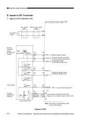
... adjustment dial varies voltage. (turn to darken brings it closer to DC Controller (1/2) DC controller/DC power supply PCB AC power supply Door switch SW1 Delivery door switch SW2 J104 J103 Density correction switch (PC420/430/ FC220) SW606 0 1 2 (bottom: lightens) (top: darkens) J601 -20(-15) J601 -2 J601 ... on any key or density correction switch allows input -22 KEYR 3 of oscillation signal. (PC420/430/FC220 only) J202 -4 DGT 0 J202 -8 DGT 1 Oscillation signal (output; CANON PC400/420/430,FC200/220 REV.0 JAN.1998 PRINTED IN JAPAN (IMPRIME AU JAPON) in parentheses refers to DC ...
... adjustment dial varies voltage. (turn to darken brings it closer to DC Controller (1/2) DC controller/DC power supply PCB AC power supply Door switch SW1 Delivery door switch SW2 J104 J103 Density correction switch (PC420/430/ FC220) SW606 0 1 2 (bottom: lightens) (top: darkens) J601 -20(-15) J601 -2 J601 ... on any key or density correction switch allows input -22 KEYR 3 of oscillation signal. (PC420/430/FC220 only) J202 -4 DGT 0 J202 -8 DGT 1 Oscillation signal (output; CANON PC400/420/430,FC200/220 REV.0 JAN.1998 PRINTED IN JAPAN (IMPRIME AU JAPON) in parentheses refers to DC ...
Service Manual
Page 39
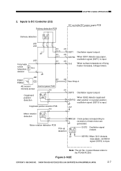
...up detection Q131 DGT2 Oscillation signal (output) KEYR0 When Q131 detects copy paper, oscillation signal (DGT2) is input. CANON PC400/420/430,FC200/220 REV.0 JAN.1998 PRINTED IN JAPAN (IMPRIME AU JAPON) 2-7 in parentheses refers to -3 revolution of... fixing heater increases, voltage lowers. Inputs to DC Controller (2/2) Delivery detection PCB DC controller/DC power supply PCB Delivery detection Q801 J801 J603 Fixing heater surface temperature detection J603 ...
...up detection Q131 DGT2 Oscillation signal (output) KEYR0 When Q131 detects copy paper, oscillation signal (DGT2) is input. CANON PC400/420/430,FC200/220 REV.0 JAN.1998 PRINTED IN JAPAN (IMPRIME AU JAPON) 2-7 in parentheses refers to -3 revolution of... fixing heater increases, voltage lowers. Inputs to DC Controller (2/2) Delivery detection PCB DC controller/DC power supply PCB Delivery detection Q801 J801 J603 Fixing heater surface temperature detection J603 ...
Service Manual
Page 40
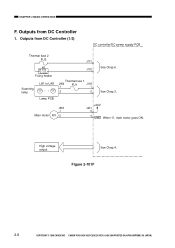
Outputs from DC Controller 1. Lamp PCB J903 -1 Main motor M1 -2 +24V J201 -5 -4 MMD When '0', main motor goes ON. J102 Fixing heater Scanning lamp LA1 to LA8 Thermal fuse 1 J906 FU1 J108 -1 -1 -2 -2 See Chap.3. Figure 2-101F 2-8 COPYRIGHT © 1998 CANON INC. CANON PC400/420/430,FC200/220 REV.0 JAN.1998 PRINTED IN JAPAN (IMPRIME AU JAPON) CHAPTER 2 BASIC OPERATION F. High voltage output See Chap.4. Outputs from DC Controller (1/2) DC controller/DC power supply PCB Thermal fuse 2 FU2 H1 J101 See Chap.6.
Outputs from DC Controller 1. Lamp PCB J903 -1 Main motor M1 -2 +24V J201 -5 -4 MMD When '0', main motor goes ON. J102 Fixing heater Scanning lamp LA1 to LA8 Thermal fuse 1 J906 FU1 J108 -1 -1 -2 -2 See Chap.3. Figure 2-101F 2-8 COPYRIGHT © 1998 CANON INC. CANON PC400/420/430,FC200/220 REV.0 JAN.1998 PRINTED IN JAPAN (IMPRIME AU JAPON) CHAPTER 2 BASIC OPERATION F. High voltage output See Chap.4. Outputs from DC Controller (1/2) DC controller/DC power supply PCB Thermal fuse 2 FU2 H1 J101 See Chap.6.
Service Manual
Page 41
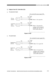
...to SL2 is switched between 24V and 15V to ensure stable operation) b. PC400/FC200 Registration solenoid J901 -1 SL1 -2 Figure 2-102F DC controller/DC power supply PCB J201 +24V -7 -6 RGSD When '0', SL1 goes ON. Copyboard drive solenoid J902 -1 SL2 -2 J101 +24V -9 -8 CBSD When '0', SL2... ON. (voltage to SL2 is switched between 24V and 15V to ensure stable operation) Figure 2-103F COPYRIGHT © 1998 CANON INC. CANON PC400/420/430,FC200/220 REV.0 JAN.1998 PRINTED IN JAPAN (IMPRIME AU JAPON) 2-9 Outputs from DC Controller (2/2) a. CHAPTER 2 BASIC OPERATION 2.
...to SL2 is switched between 24V and 15V to ensure stable operation) b. PC400/FC200 Registration solenoid J901 -1 SL1 -2 Figure 2-102F DC controller/DC power supply PCB J201 +24V -7 -6 RGSD When '0', SL1 goes ON. Copyboard drive solenoid J902 -1 SL2 -2 J101 +24V -9 -8 CBSD When '0', SL2... ON. (voltage to SL2 is switched between 24V and 15V to ensure stable operation) Figure 2-103F COPYRIGHT © 1998 CANON INC. CANON PC400/420/430,FC200/220 REV.0 JAN.1998 PRINTED IN JAPAN (IMPRIME AU JAPON) 2-9 Outputs from DC Controller (2/2) a. CHAPTER 2 BASIC OPERATION 2.

Service Manual
Page 47
...J201 Copyboard drive gear -10 Copyboard drive solenoid drive command (CBSD) J201 -9 Copyboard drive solenoid SL2 DC controller/ DC power supply PCB Forward Forward/Reverse Reverse gear switching mechanism gear J201 -4 Main motor drive command (MMD) M1 Main motor Figure 3-102B Front... paper transport and the movement (forward, reverse, stop operations by the copyboard drive solenoid (SL2) and forward/ reverse switching mechanism. CANON PC400/420/430,FC200/220 REV.0 JAN.1998 PRINTED IN JAPAN (IMPRIME AU JAPON) 3-3 see Table 3101B. CHAPTER 3 EXPOSURE SYSTEM 2. Controlling the...
...J201 Copyboard drive gear -10 Copyboard drive solenoid drive command (CBSD) J201 -9 Copyboard drive solenoid SL2 DC controller/ DC power supply PCB Forward Forward/Reverse Reverse gear switching mechanism gear J201 -4 Main motor drive command (MMD) M1 Main motor Figure 3-102B Front... paper transport and the movement (forward, reverse, stop operations by the copyboard drive solenoid (SL2) and forward/ reverse switching mechanism. CANON PC400/420/430,FC200/220 REV.0 JAN.1998 PRINTED IN JAPAN (IMPRIME AU JAPON) 3-3 see Table 3101B. CHAPTER 3 EXPOSURE SYSTEM 2. Controlling the...

Service Manual
Page 51
... the scanning lamp ON and OFF. • Controls the intensity of the scanning lamp has stabilized. CANON PC400/420/430,FC200/220 REV.0 JAN.1998 PRINTED IN JAPAN (IMPRIME AU JAPON) 3-7 FIgure 3-201A COPYRIGHT © 1998 CANON INC. CHAPTER 3 EXPOSURE SYSTEM II. Controlling the Scanning Lamp A. Outline Figure 3-201A shows the circuit that... Lamp ON signal (LAPWM) Microprocessor VR604 - + 5V Amplifier circuit J601 -10 (-5) J202 -13 Lamp intensity sensor signal (LID) Control panel PCB DC controller/DC power supply PCB The number within parentheses represents the PC400/FC200.
... the scanning lamp ON and OFF. • Controls the intensity of the scanning lamp has stabilized. CANON PC400/420/430,FC200/220 REV.0 JAN.1998 PRINTED IN JAPAN (IMPRIME AU JAPON) 3-7 FIgure 3-201A COPYRIGHT © 1998 CANON INC. CHAPTER 3 EXPOSURE SYSTEM II. Controlling the Scanning Lamp A. Outline Figure 3-201A shows the circuit that... Lamp ON signal (LAPWM) Microprocessor VR604 - + 5V Amplifier circuit J601 -10 (-5) J202 -13 Lamp intensity sensor signal (LID) Control panel PCB DC controller/DC power supply PCB The number within parentheses represents the PC400/FC200.
Service Manual
Page 59
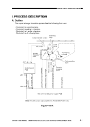
... corona high voltage Static eliminator Transfer charging high voltage Developing bias J202-13 -19 DC controller/DC power supply PCB Note : The AE sensor is provided for the PC420/430/FC220 only. CANON PC400/420/430,FC200/220 REV.0 JAN.1998 PRINTED IN JAPAN (IMPRIME AU JAPON) 4-1 Outline The copier's image formation system has...
... corona high voltage Static eliminator Transfer charging high voltage Developing bias J202-13 -19 DC controller/DC power supply PCB Note : The AE sensor is provided for the PC420/430/FC220 only. CANON PC400/420/430,FC200/220 REV.0 JAN.1998 PRINTED IN JAPAN (IMPRIME AU JAPON) 4-1 Outline The copier's image formation system has...
Service Manual
Page 63
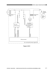
Transformer (T106) DC bias control circuit DC current detection CHPTER 4 IMAGE FORMATION SYSTEM Amplifier Transformer (T103) J6 Primary charging roller Photosensitive drum Oscillation control circuit Oscillation circuit Current detection AC bias ON command (HVPAC) DC bias ON command (HVPDC) DC bias high output command (HVPHO) Microprocessor DC controller/DC power supply PCB Figure 4-101C COPYRIGHT © 1998 CANON INC. CANON PC400/420/430,FC200/220 REV.0 JAN.1998 PRINTED IN JAPAN (IMPRIME AU JAPON) 4-5
Transformer (T106) DC bias control circuit DC current detection CHPTER 4 IMAGE FORMATION SYSTEM Amplifier Transformer (T103) J6 Primary charging roller Photosensitive drum Oscillation control circuit Oscillation circuit Current detection AC bias ON command (HVPAC) DC bias ON command (HVPDC) DC bias high output command (HVPHO) Microprocessor DC controller/DC power supply PCB Figure 4-101C COPYRIGHT © 1998 CANON INC. CANON PC400/420/430,FC200/220 REV.0 JAN.1998 PRINTED IN JAPAN (IMPRIME AU JAPON) 4-5
Service Manual
Page 67
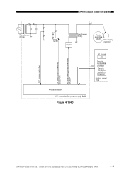
Transformer (T106) DC voltage detection DC bias control command (DCBPWM) AC bias timing pulse command (ACBTP) CHPTER 4 IMAGE FORMATION SYSTEM J7 5V Q146 Transformer (T104) Amplifier Photosensitive drum Developing cylinder AE signal AE J202 Density control dial VR601 Density correction switch SW606 Control panel PCB Microprocessor DC controller/DC power supply PCB Figure 4-104D COPYRIGHT © 1998 CANON INC. CANON PC400/420/430,FC200/220 REV.0 JAN.1998 PRINTED IN JAPAN (IMPRIME AU JAPON) 4-9
Transformer (T106) DC voltage detection DC bias control command (DCBPWM) AC bias timing pulse command (ACBTP) CHPTER 4 IMAGE FORMATION SYSTEM J7 5V Q146 Transformer (T104) Amplifier Photosensitive drum Developing cylinder AE signal AE J202 Density control dial VR601 Density correction switch SW606 Control panel PCB Microprocessor DC controller/DC power supply PCB Figure 4-104D COPYRIGHT © 1998 CANON INC. CANON PC400/420/430,FC200/220 REV.0 JAN.1998 PRINTED IN JAPAN (IMPRIME AU JAPON) 4-9

Service Manual
Page 71
... bias ON command (TREV) Voltage sensor (analog signal) Transfer DC bias ON command (HVTDC) Transfer DC bias control command (DCTPWM) Microprocessor DC controller/DC power supply PCB Figure 4-101E COPYRIGHT © 1998 CANON INC. CANON PC400/420/430,FC200/220 REV.0 JAN.1998 PRINTED IN JAPAN (IMPRIME AU JAPON) 4-13
... bias ON command (TREV) Voltage sensor (analog signal) Transfer DC bias ON command (HVTDC) Transfer DC bias control command (DCTPWM) Microprocessor DC controller/DC power supply PCB Figure 4-101E COPYRIGHT © 1998 CANON INC. CANON PC400/420/430,FC200/220 REV.0 JAN.1998 PRINTED IN JAPAN (IMPRIME AU JAPON) 4-13

Service Manual
Page 74
CANON PC400/420/430,FC200/220 REV.0 JAN.1998 PRINTED IN JAPAN (IMPRIME AU JAPON) CHPTER 4 IMAGE FORMATION SYSTEM AE sensor PD602 Forward Scanning lamp Lens array J621 -2 J621 | -1 { Photosensitive drum Developing cylinder 4V (approx.) VR602 VR603 | { J601 J202 -4 -19 5V Amplifier circuit DC bias control circuit DCBPWM AE signal Microprocessor Control panel PCB DC controller/DC power supply PCB Figure 4-103F 4-16 COPYRIGHT © 1998 CANON INC.
CANON PC400/420/430,FC200/220 REV.0 JAN.1998 PRINTED IN JAPAN (IMPRIME AU JAPON) CHPTER 4 IMAGE FORMATION SYSTEM AE sensor PD602 Forward Scanning lamp Lens array J621 -2 J621 | -1 { Photosensitive drum Developing cylinder 4V (approx.) VR602 VR603 | { J601 J202 -4 -19 5V Amplifier circuit DC bias control circuit DCBPWM AE signal Microprocessor Control panel PCB DC controller/DC power supply PCB Figure 4-103F 4-16 COPYRIGHT © 1998 CANON INC.

Service Manual
Page 81
... edge matches that of the PC400/FC200. if copy paper fails to the transfer, separation, and fixing assemblies before it reaches the copy tray. CANON PC400/420/430,FC200/220 REV.0 JAN.1998 PRINTED IN JAPAN (IMPRIME AU JAPON) 5-1 The delivery of copy paper is then moved to reach or move past...-up roller starts to rotate when the Copy Start key is pressed in the case of the PC420/430/FC220 and when paper is controlled by the delivery sensor (Q801); DC controller/DC power supply PCB Delivery sensor signal Main motor drive command (MMD) Pick-up sensor signal Pick-up solenoid drive...
... edge matches that of the PC400/FC200. if copy paper fails to the transfer, separation, and fixing assemblies before it reaches the copy tray. CANON PC400/420/430,FC200/220 REV.0 JAN.1998 PRINTED IN JAPAN (IMPRIME AU JAPON) 5-1 The delivery of copy paper is then moved to reach or move past...-up roller starts to rotate when the Copy Start key is pressed in the case of the PC420/430/FC220 and when paper is controlled by the delivery sensor (Q801); DC controller/DC power supply PCB Delivery sensor signal Main motor drive command (MMD) Pick-up sensor signal Pick-up solenoid drive...


