

Parts Catalog
Page 1
FAXPHONE B540A3550 MuMPASS 800 NOV. 1995 PRINTED IN JAPAN (IMPRIME AU JAPAN) FAXPHONE B540/B550 MultiPASS.800 Document Processing System PARTS CATALOG REVISION 1 ..._ FAXPHONE B54O FAXPHONE B550 FAXPHONE B55O MultiPASS 800 H12-0522 H12-O272 H12-O276 1112-0302 120V 120V 120V 12OV USAICND USA/CND LIN USAICND Canon NOV.1995 HY8-39A6-010 COPYRIGHT © 1995 CANON INC.
FAXPHONE B540A3550 MuMPASS 800 NOV. 1995 PRINTED IN JAPAN (IMPRIME AU JAPAN) FAXPHONE B540/B550 MultiPASS.800 Document Processing System PARTS CATALOG REVISION 1 ..._ FAXPHONE B54O FAXPHONE B550 FAXPHONE B55O MultiPASS 800 H12-0522 H12-O272 H12-O276 1112-0302 120V 120V 120V 12OV USAICND USA/CND LIN USAICND Canon NOV.1995 HY8-39A6-010 COPYRIGHT © 1995 CANON INC.

Parts Catalog
Page 3
.... Under the copyright laws, this manual, Canon will issue a new editions of the individual companies. Copyright * 1995 by Solutions, Inc.® Super GLUE He. Parts lists were created using Helix Technology® Helix Express® and converted to learn technical theory, installation, maintenance, and repair of this manual may be copied, reproduced or translated into another language, in whole or in the content...
.... Under the copyright laws, this manual, Canon will issue a new editions of the individual companies. Copyright * 1995 by Solutions, Inc.® Super GLUE He. Parts lists were created using Helix Technology® Helix Express® and converted to learn technical theory, installation, maintenance, and repair of this manual may be copied, reproduced or translated into another language, in whole or in the content...

Parts Catalog
Page 5
... in the parts list. II. PARTS LAYOUT & PARTS LIST Parts layout illustration a) Parts search Find a part from the NUMERICAL INDEX, II Note: If parts have the same or similar shape but different specifications, their key number is a list of the product. When a unit in the illustration indicate the connection locations of the disassembly will be disassemble further, a reference illustration page of cables and screws. When replacing parts, or if...
... in the parts list. II. PARTS LAYOUT & PARTS LIST Parts layout illustration a) Parts search Find a part from the NUMERICAL INDEX, II Note: If parts have the same or similar shape but different specifications, their key number is a list of the product. When a unit in the illustration indicate the connection locations of the disassembly will be disassemble further, a reference illustration page of cables and screws. When replacing parts, or if...

Parts Catalog
Page 6
III. III REVISION HISTORY REVISON 0 1 CONTENT Original MuItiPASS 800 added Update to Service Information HS-B0E-0010-01, as issued by Canon Inc.
III. III REVISION HISTORY REVISON 0 1 CONTENT Original MuItiPASS 800 added Update to Service Information HS-B0E-0010-01, as issued by Canon Inc.

Parts Catalog
Page 9
... 800 POWER SUPPLY UNIT & ASF & MAIN BOARD ASS'Y . 4 6 PRINTER ASS'Y & INK See Page 2-17 FIGURE 10 ABSORBER & LOWER COVER UNIT See Page 2-19 t 5.4 Ay A.arJS -ow 1.0 ,0.53 fItNMEt44 3 Nopop 1-87 lof Or *swum* olegrom otitis unle .p.9. rAtgear 4 I 2 ONN•notO 5 bepeo•Pvn••d•-U mg eidURE JAI OPERATION PANEL UNIT FIGURE 11 & SEPARATION GUIDE & SCANNER BASE UNIT See Page 2-21 FAXPHONE B540 FIGURE 12 OPERATION PANEL...
... 800 POWER SUPPLY UNIT & ASF & MAIN BOARD ASS'Y . 4 6 PRINTER ASS'Y & INK See Page 2-17 FIGURE 10 ABSORBER & LOWER COVER UNIT See Page 2-19 t 5.4 Ay A.arJS -ow 1.0 ,0.53 fItNMEt44 3 Nopop 1-87 lof Or *swum* olegrom otitis unle .p.9. rAtgear 4 I 2 ONN•notO 5 bepeo•Pvn••d•-U mg eidURE JAI OPERATION PANEL UNIT FIGURE 11 & SEPARATION GUIDE & SCANNER BASE UNIT See Page 2-21 FAXPHONE B540 FIGURE 12 OPERATION PANEL...
Parts Catalog
Page 18
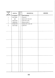
HT1.2056.000 R Q NA T DESCRIPTION K Y N 1 USER'S GUIDE (ENGI HB1-1192-000 1 FACEPLATE 89381 1 PAPER OUTPUT TRAY ASS'Y HG5-0416-000 1 PAPER TRAY COVER HH2-2501-000 1 MODULAR CORD, 2P WT3-5021.000^ 1 POWER SUPPLY CORD, 120V HF5.0113.020 1 PAPER TRAY REMARKS 2-2 i• 1 2 3 4 8 9 10 PART No. FIGURE & KEY No.
HT1.2056.000 R Q NA T DESCRIPTION K Y N 1 USER'S GUIDE (ENGI HB1-1192-000 1 FACEPLATE 89381 1 PAPER OUTPUT TRAY ASS'Y HG5-0416-000 1 PAPER TRAY COVER HH2-2501-000 1 MODULAR CORD, 2P WT3-5021.000^ 1 POWER SUPPLY CORD, 120V HF5.0113.020 1 PAPER TRAY REMARKS 2-2 i• 1 2 3 4 8 9 10 PART No. FIGURE & KEY No.
Parts Catalog
Page 20
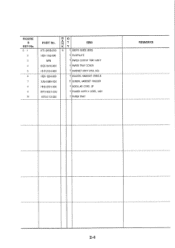
FIGURE & KEY No. 2- 1 2 3 4 5 6 7 8 9 10 PART No. HT1.2058.000 HB1.1192.000 NPN HG5-0416-000 HH7-2104-000 HB1-1264-0O0 XA9.0689.000 HH2-2501.000 WT3-5021-000 HF5-0113-020 R 0 AN T cesc K Y N 1 USER'S GUIDE (ENG) I FACEPLATE I PAPER OUTPUT TRAY ASS'Y 1 PAPER TRAY COVER 1 HANDSET ASS'Y (USA, AG) 1 HOLDER, HANDSET CRADLE 2 SCREW, HANDSET HOLDER I MODULAR CORD, 2P 1 POWER SUPPLY CORD, 120V 1 PAPER TRAY REMARKS - - 2-4
FIGURE & KEY No. 2- 1 2 3 4 5 6 7 8 9 10 PART No. HT1.2058.000 HB1.1192.000 NPN HG5-0416-000 HH7-2104-000 HB1-1264-0O0 XA9.0689.000 HH2-2501.000 WT3-5021-000 HF5-0113-020 R 0 AN T cesc K Y N 1 USER'S GUIDE (ENG) I FACEPLATE I PAPER OUTPUT TRAY ASS'Y 1 PAPER TRAY COVER 1 HANDSET ASS'Y (USA, AG) 1 HOLDER, HANDSET CRADLE 2 SCREW, HANDSET HOLDER I MODULAR CORD, 2P 1 POWER SUPPLY CORD, 120V 1 PAPER TRAY REMARKS - - 2-4

Parts Catalog
Page 22
FIGURE & KEY No. 3- 1 2 3 4 5 6 7 8 9 10 11 12 PART No. HT1-2060-000 HT1.2062-000 HB1-1262.000 NPN HG5-0416-000 HH7-2104-000 HB1.1283.000 XA9.0689.000 HH2-2501.000 WT3-5021-000 HF5-0113.020 HG5.0643.000 R a N T DESC K Y N 1 USER'S GUIDE (ENG) N 1 USER'S GUIDE, DESKTOP MANAGER 1 FACEPLATE 1 PAPER OUTPUT TRAY ASS'Y 1 PAPER TRAY COVER 1 HANDSET ASS'Y (USA, AG) 1 HOLDER, HANDSET CRADLE 2 SCREW, HANDSET HOLDER I MODULAR CORD, 2P 1 POWER SUPPLY CORD, 120V 1 PAPER TRAY 1 3.5"FD DRIVER SOFTWARE REMARKS -,- - - 2-6
FIGURE & KEY No. 3- 1 2 3 4 5 6 7 8 9 10 11 12 PART No. HT1-2060-000 HT1.2062-000 HB1-1262.000 NPN HG5-0416-000 HH7-2104-000 HB1.1283.000 XA9.0689.000 HH2-2501.000 WT3-5021-000 HF5-0113.020 HG5.0643.000 R a N T DESC K Y N 1 USER'S GUIDE (ENG) N 1 USER'S GUIDE, DESKTOP MANAGER 1 FACEPLATE 1 PAPER OUTPUT TRAY ASS'Y 1 PAPER TRAY COVER 1 HANDSET ASS'Y (USA, AG) 1 HOLDER, HANDSET CRADLE 2 SCREW, HANDSET HOLDER I MODULAR CORD, 2P 1 POWER SUPPLY CORD, 120V 1 PAPER TRAY 1 3.5"FD DRIVER SOFTWARE REMARKS -,- - - 2-6
Parts Catalog
Page 35
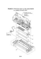
See page 5-3 (FIGURE 10-a) a F 7 See page 5-4 I (FIGURE FO-b) i I 6 5 0 4*11f.r1c." 4 3 2 2-19 FIGURE 10 PRINTER ASS'Y & INK ABSORBER & LOWER COVER UNIT 1 See page 2-43 to 2.55 for the disassembly diagram of this unit.
See page 5-3 (FIGURE 10-a) a F 7 See page 5-4 I (FIGURE FO-b) i I 6 5 0 4*11f.r1c." 4 3 2 2-19 FIGURE 10 PRINTER ASS'Y & INK ABSORBER & LOWER COVER UNIT 1 See page 2-43 to 2.55 for the disassembly diagram of this unit.
Parts Catalog
Page 37
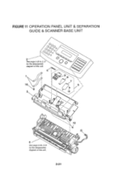
FIGURE 11 OPERATION PANEL UNIT & SEPARATION GUIDE & SCANNER BASE UNIT O° OOO OOOOOOOo 2 See page 2-23 to 2-27 for the disassembly diagram of this unit. 4 10 3 Q 7 5 \ / / 12 B See page 2-29, 2-31 for the disassembly diagram of this unit 2-21
FIGURE 11 OPERATION PANEL UNIT & SEPARATION GUIDE & SCANNER BASE UNIT O° OOO OOOOOOOo 2 See page 2-23 to 2-27 for the disassembly diagram of this unit. 4 10 3 Q 7 5 \ / / 12 B See page 2-29, 2-31 for the disassembly diagram of this unit 2-21
Parts Catalog
Page 56
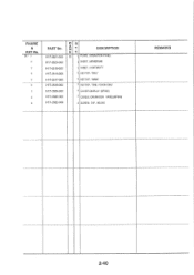
FIGURE & KEY No. 20 - 1 2 3 4 5 6 7 8 9 PART No. REMARKS 2-40 HY7.2621.000 HY7-2620-000 HY7-2619-000 HY7-2616-000 HY7-2617-000 HY7-2618-000 HY7-2626-000 HY7.2625-000 HY7-2622-000 R O N T K 1', DESCRIPTION N 1 PLATE, OPERATION PANEL 1 SHEET, MEMBRANE 1 SHEET, CONTINUITY 1 KEYTOP, "DIAL' 1 KEYTOP, WAIN' 1 KEYTOP, 'ONE TOUCH DIAL' I COVER DISPLAY (MP800) I COVER, OPERATION PANEL(MP800) 4 SCREW, TAP, M3.5X6 -.._-- - - -----
FIGURE & KEY No. 20 - 1 2 3 4 5 6 7 8 9 PART No. REMARKS 2-40 HY7.2621.000 HY7-2620-000 HY7-2619-000 HY7-2616-000 HY7-2617-000 HY7-2618-000 HY7-2626-000 HY7.2625-000 HY7-2622-000 R O N T K 1', DESCRIPTION N 1 PLATE, OPERATION PANEL 1 SHEET, MEMBRANE 1 SHEET, CONTINUITY 1 KEYTOP, "DIAL' 1 KEYTOP, WAIN' 1 KEYTOP, 'ONE TOUCH DIAL' I COVER DISPLAY (MP800) I COVER, OPERATION PANEL(MP800) 4 SCREW, TAP, M3.5X6 -.._-- - - -----

Parts Catalog
Page 66
FIGURE 26 PAPER FEED SECTION (1) 1 See page 5-7 (FIGURE 26-a) Break this part to remove, and replace it with a new one. 0o I 8 r• 13 Break this part to 3 remove, and replace it with a new one. 4 See page 5-7 (FIGURE 26-b) 7 6 5 2-51
FIGURE 26 PAPER FEED SECTION (1) 1 See page 5-7 (FIGURE 26-a) Break this part to remove, and replace it with a new one. 0o I 8 r• 13 Break this part to 3 remove, and replace it with a new one. 4 See page 5-7 (FIGURE 26-b) 7 6 5 2-51
Parts Catalog
Page 87
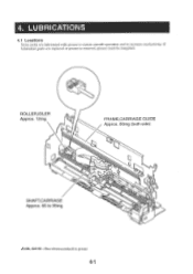
4. ROLLER,IDLER Approx. 12mg FRAME,CARRIAGE GUIDE Approx. 60mg (both side) SHAFT,CARRIAGE Approx. 65 to increase conductivity. If lubricated parts are lubricated with grease to ensure smooth operation and to 95mg FLOIL G311S : Non-electroconductive grease 4-1 a lO LUBRICATIONS 4.1 Locations Some parts are replaced or grease is removed, grease must be reapplied.
4. ROLLER,IDLER Approx. 12mg FRAME,CARRIAGE GUIDE Approx. 60mg (both side) SHAFT,CARRIAGE Approx. 65 to increase conductivity. If lubricated parts are lubricated with grease to ensure smooth operation and to 95mg FLOIL G311S : Non-electroconductive grease 4-1 a lO LUBRICATIONS 4.1 Locations Some parts are replaced or grease is removed, grease must be reapplied.

Parts Catalog
Page 89
Then slide the Scanner Unit in order to the Lower Cover Unit 5-1 GUIDE TO REPLACEMENT FIGURE 4-a See Page FIGURE 4-b 2 - 7 See Page 2 -7 O Follow the procedure described above on to remove the COVER, LOGIC BOARD, When removing the SCANNER UNIT, insert a screwdriver into the holes at the right and left , and with a screw driver inserted into the handset rest screw hole ®, so that the cover is prised...
Then slide the Scanner Unit in order to the Lower Cover Unit 5-1 GUIDE TO REPLACEMENT FIGURE 4-a See Page FIGURE 4-b 2 - 7 See Page 2 -7 O Follow the procedure described above on to remove the COVER, LOGIC BOARD, When removing the SCANNER UNIT, insert a screwdriver into the holes at the right and left , and with a screw driver inserted into the handset rest screw hole ®, so that the cover is prised...

Parts Catalog
Page 91
... a POWER SUPPLY UNIT Thread the cables for the POWER SUPPLY UNIT, and When removing the AUTO SHEET FEEDER ASS'Y, PULSE MOTOR, CARRIAGE as shown above. FIGURE 8-a See Page 2 - 15/17/49 FIGURE 8-b See Page 2 -15/17 PULSE MOTOR. release the tabs holding the printer chassis.... illustration in the left and right, as shown above , corresponding to the alphabet letters in Chapter 2. 5-3 FIGURE 8-c See Page 2 - 15/17 FIGURE 10-a See Page 2-19 A B C J U 0 aB 0O H F K G Insert the connectors into the locations in the illustration When removing the PRINTER...
... a POWER SUPPLY UNIT Thread the cables for the POWER SUPPLY UNIT, and When removing the AUTO SHEET FEEDER ASS'Y, PULSE MOTOR, CARRIAGE as shown above. FIGURE 8-a See Page 2 - 15/17/49 FIGURE 8-b See Page 2 -15/17 PULSE MOTOR. release the tabs holding the printer chassis.... illustration in the left and right, as shown above , corresponding to the alphabet letters in Chapter 2. 5-3 FIGURE 8-c See Page 2 - 15/17 FIGURE 10-a See Page 2-19 A B C J U 0 aB 0O H F K G Insert the connectors into the locations in the illustration When removing the PRINTER...
Parts Catalog
Page 93
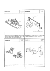
FIGURE 16-a See Page 2-31 FIGURE 16-b See Page 2-31 88-90mm Blue 90 88-90mm 88-90mm 88-90mm Blue Attach the CONTACT SENSOR ASS'Y as shown in the Fold the FLAT CABLE (CS) as shown in the illustration. diagram. 5-5 slide in the direction of the main unit. FIGURE 12-d See Page FIGURE 15-a 2 - 23/25/27 See Page 2.29 SHIELD,LIGHT ROLLER,DOCUMENT FEED When removing the OPCNT BOARD ASS'Y, free the When attaching the SHIELD, LIGHT, fix so that the edge board from the OPERATION PANEL ASS'Y boss @, and of the "V" mark is facing the centre of the arrow in the diagram.
FIGURE 16-a See Page 2-31 FIGURE 16-b See Page 2-31 88-90mm Blue 90 88-90mm 88-90mm 88-90mm Blue Attach the CONTACT SENSOR ASS'Y as shown in the Fold the FLAT CABLE (CS) as shown in the illustration. diagram. 5-5 slide in the direction of the main unit. FIGURE 12-d See Page FIGURE 15-a 2 - 23/25/27 See Page 2.29 SHIELD,LIGHT ROLLER,DOCUMENT FEED When removing the OPCNT BOARD ASS'Y, free the When attaching the SHIELD, LIGHT, fix so that the edge board from the OPERATION PANEL ASS'Y boss @, and of the "V" mark is facing the centre of the arrow in the diagram.

Parts Catalog
Page 96
... the arrow 0. When removing the PICK UP ROLLER ASS'Y, bend the tabs in the direction of the arrows, make sure that the GEAR, CAM and PICKUP ROLLER are loosened, head gap adjustment wil be required. FIGURE 27-b See Page 2-53 FIGURE 28-a Screw See Page 2-55 ARM,PAPER SENSOR Alf these screws are attached so that the marks line up. 5-8 FIGURE...
... the arrow 0. When removing the PICK UP ROLLER ASS'Y, bend the tabs in the direction of the arrows, make sure that the GEAR, CAM and PICKUP ROLLER are loosened, head gap adjustment wil be required. FIGURE 27-b See Page 2-53 FIGURE 28-a Screw See Page 2-55 ARM,PAPER SENSOR Alf these screws are attached so that the marks line up. 5-8 FIGURE...

Parts Catalog
Page 99
... SEPARATION PLATE, SCANNER DRIVE ROLLER, PAPER FEED PAPER LIFTING PLATE ASS'Y LOWER COVER UNIT SEPARATION GUIDE UNIT PAPER TRAY SEPARATION GUIDE ASSN OPERATION PANEL ASS'Y (8550) OPCNT BOARD ASS'Y SEPARATION ROLLER ASS'? CONTACT SENSOR ASS'Y DOCUMENT FEED ROLLER ASS'Y FRONT COVER ASS'Y PAPER TRAY COVER PRINTER ASS'Y CARRIAGE ASS'Y CARRIAGE RIBBON CABLE ASS'Y AUTO SHEET FEEDER ASS'Y PAPER PICKUP ROLLER ASS'Y PAPER EJECT ROLLER ASS'Y OPERATION PANEL ASS'Y (B540) MAIN BOARD ASS'Y MAIN BOARD ASS'Y OPERATION PANEL ASS'Y (MP 800) 3.5'FD DRIVER SOFTWARE FLAT CABLE FLAT CABLE CABLE WITH CONNECTOR...
... SEPARATION PLATE, SCANNER DRIVE ROLLER, PAPER FEED PAPER LIFTING PLATE ASS'Y LOWER COVER UNIT SEPARATION GUIDE UNIT PAPER TRAY SEPARATION GUIDE ASSN OPERATION PANEL ASS'Y (8550) OPCNT BOARD ASS'Y SEPARATION ROLLER ASS'? CONTACT SENSOR ASS'Y DOCUMENT FEED ROLLER ASS'Y FRONT COVER ASS'Y PAPER TRAY COVER PRINTER ASS'Y CARRIAGE ASS'Y CARRIAGE RIBBON CABLE ASS'Y AUTO SHEET FEEDER ASS'Y PAPER PICKUP ROLLER ASS'Y PAPER EJECT ROLLER ASS'Y OPERATION PANEL ASS'Y (B540) MAIN BOARD ASS'Y MAIN BOARD ASS'Y OPERATION PANEL ASS'Y (MP 800) 3.5'FD DRIVER SOFTWARE FLAT CABLE FLAT CABLE CABLE WITH CONNECTOR...

Parts Catalog
Page 100
..., TRANSMISSION GEAR, TRANSMISSION CAM, ROD SPRING. COIL SPRING, COIL SCREW, EIH(RED) M3X4 SCREW, M2.6X3.5 USER'S GUIDE (ENG) USER'S GUIDE (ENG) USER'S GUIDE, DESKTOP MANAGER FUSE, 125V, 2A COVER, DISPLAY KEYTOP, "DIAL' KEYTOP, 'MAIN' KEYTOP, 'ONE TOUCH DIAL" SHEET, CONTINUITY SHEET, MEMBRANE PLATE, OPERATION PANEL PART NUMBER FIGURE & KEY No. T 2 27 - 1 22 - 7 27 - 2 28 - 3 28 - 2 28 - 1 7- 3 26 - 1 26 - 7 26 - 13 26 - 11 26...
..., TRANSMISSION GEAR, TRANSMISSION CAM, ROD SPRING. COIL SPRING, COIL SCREW, EIH(RED) M3X4 SCREW, M2.6X3.5 USER'S GUIDE (ENG) USER'S GUIDE (ENG) USER'S GUIDE, DESKTOP MANAGER FUSE, 125V, 2A COVER, DISPLAY KEYTOP, "DIAL' KEYTOP, 'MAIN' KEYTOP, 'ONE TOUCH DIAL" SHEET, CONTINUITY SHEET, MEMBRANE PLATE, OPERATION PANEL PART NUMBER FIGURE & KEY No. T 2 27 - 1 22 - 7 27 - 2 28 - 3 28 - 2 28 - 1 7- 3 26 - 1 26 - 7 26 - 13 26 - 11 26...
Parts Catalog
Page 101
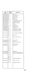
SHORT POWER SUPPLY CORD, 120V SCREW, TP M3XB NUT, SUS SCREW, HANDSET HOLDER SCREW, PH3X12 (S) SCREW. M3X4 SCREW, M2X6 SCREW, TAP, BINDING HEAD, M3X6 SCREW, TAP TIGHT, BINDING HEAD SCREW, BINDING HEAD M3X10 SCREW, TP, PH M3X4 RETAINING RING (E-TYPE) 6-3 PART NUMBER FIGURE & KEY No. T 3 WK1...15 - 13 CLIP, SHAFT GEAR, SLOW DOWN ROLLER, IDLER BRACKET, IDLER SPRING, COIL FOOT, PRINTER COVER, WASTE INK ABSORBER ABSORBER, WASTE INK ABSORBER, WASTE INK SPUR SPUR SHAFT WASHER, PLAIN ROLLER, PRESSURE PURGE UNIT PULSE MOTOR, PAPER FEED GREASE FLOIL G311S (20GS) POLYSENE BATTERY LITHIUM BATTERY...
SHORT POWER SUPPLY CORD, 120V SCREW, TP M3XB NUT, SUS SCREW, HANDSET HOLDER SCREW, PH3X12 (S) SCREW. M3X4 SCREW, M2X6 SCREW, TAP, BINDING HEAD, M3X6 SCREW, TAP TIGHT, BINDING HEAD SCREW, BINDING HEAD M3X10 SCREW, TP, PH M3X4 RETAINING RING (E-TYPE) 6-3 PART NUMBER FIGURE & KEY No. T 3 WK1...15 - 13 CLIP, SHAFT GEAR, SLOW DOWN ROLLER, IDLER BRACKET, IDLER SPRING, COIL FOOT, PRINTER COVER, WASTE INK ABSORBER ABSORBER, WASTE INK ABSORBER, WASTE INK SPUR SPUR SHAFT WASHER, PLAIN ROLLER, PRESSURE PURGE UNIT PULSE MOTOR, PAPER FEED GREASE FLOIL G311S (20GS) POLYSENE BATTERY LITHIUM BATTERY...


