
Service Manual
Page 5
...: 1. All service persons are subject to change without notice for product improvement or other purposes, and major changes will be communicated in terms of from sensors to circuit.) In addition, the asterisk (*) as in the machine." In the digital circuits, '1'is used to the timing of the electric signal. ence to...
...: 1. All service persons are subject to change without notice for product improvement or other purposes, and major changes will be communicated in terms of from sensors to circuit.) In addition, the asterisk (*) as in the machine." In the digital circuits, '1'is used to the timing of the electric signal. ence to...
Service Manual
Page 7
...View (ADF)...1- 3 1.1.1.4 Control panel...1- 4 1.1.2 Safety ...1- 6 1.1.2.1 Safety of the Host Machine's Laser Mechanism ...1- 6 1.1.2.2 CDRH Regulations...1- 6 1.1.2.3 Handling of the Laser Assembly ...1- 6 1.1.2.4 Safety of the Toner ...1- 6 1.1.2.5 Fire Attention...1- 6 1.1.2.6 Points no Note ...Constraction...3- 1 3.1.1 Specifications / Control / Function List ...3- 1 3.1.2 Major Components ...3- 1 3.2 Various Control ...3- 3 3.2.1 Dirt Sensor Control ...3- 3 3.2.1.1 Outline...3- 3 3.3 Parts Replacement Procedure ...3- 5 3.3.1 Scanner Unit...3- 5 3.3.1.1 Preparation for Removing the Control...
...View (ADF)...1- 3 1.1.1.4 Control panel...1- 4 1.1.2 Safety ...1- 6 1.1.2.1 Safety of the Host Machine's Laser Mechanism ...1- 6 1.1.2.2 CDRH Regulations...1- 6 1.1.2.3 Handling of the Laser Assembly ...1- 6 1.1.2.4 Safety of the Toner ...1- 6 1.1.2.5 Fire Attention...1- 6 1.1.2.6 Points no Note ...Constraction...3- 1 3.1.1 Specifications / Control / Function List ...3- 1 3.1.2 Major Components ...3- 1 3.2 Various Control ...3- 3 3.2.1 Dirt Sensor Control ...3- 3 3.2.1.1 Outline...3- 3 3.3 Parts Replacement Procedure ...3- 5 3.3.1 Scanner Unit...3- 5 3.3.1.1 Preparation for Removing the Control...
Service Manual
Page 10
... ...11- 1 Chapter 12 Correcting Faulty Images 12.1 Outline of Electrical Components ...12- 1 12.1.1 Clutch/Solenoid/Motor/Fan...12- 1 12.1.1.1 List of Solenoids/Motors...12- 1 12.1.2 Sensor...12- 2 12.1.2.1 List of Sensors ...12- 2 12.1.3 PCBs ...12- 3 12.1.3.1 List of PCBs ...12- 3
... ...11- 1 Chapter 12 Correcting Faulty Images 12.1 Outline of Electrical Components ...12- 1 12.1.1 Clutch/Solenoid/Motor/Fan...12- 1 12.1.1.1 List of Solenoids/Motors...12- 1 12.1.2 Sensor...12- 2 12.1.2.1 List of Sensors ...12- 2 12.1.3 PCBs ...12- 3 12.1.3.1 List of PCBs ...12- 3
Service Manual
Page 25
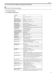
... type Cassette capacity Multifeeder tray capacity Delivery tray stack Continuous reproduction Energy save mode Fixed Desktop (ADF standard type) LED Contact Sensor Reading Method OPC drum Indirect electrostatic copying method Semiconductor laser Roller contact charging method Dry system - Dispose used battery according to the instruction manual. 1.1.3 Product Specifications 1.1.3.1 Host Machine Specifications Copyboard...
... type Cassette capacity Multifeeder tray capacity Delivery tray stack Continuous reproduction Energy save mode Fixed Desktop (ADF standard type) LED Contact Sensor Reading Method OPC drum Indirect electrostatic copying method Semiconductor laser Roller contact charging method Dry system - Dispose used battery according to the instruction manual. 1.1.3 Product Specifications 1.1.3.1 Host Machine Specifications Copyboard...

Service Manual
Page 39
Contents Contents 3.1 Basic Constraction ...3-1 3.1.1 Specifications / Control / Function List ...3-1 3.1.2 Major Components...3-1 3.2 Various Control...3-3 3.2.1 Dirt Sensor Control ...3-3 3.2.1.1 Outline...3-3 3.3 Parts Replacement Procedure...3-5 3.3.1 Scanner Unit...3-5 3.3.1.1 Preparation for Removing the Control Panel Assembly ...3-5 3.3.1.2 Removing the Control Panel Assembly ...3-5 3.3.2 Book Motor ...3-5 3.3.2.1 Preparation for Removing the Flat Bed Motor ...3-5 3.3.2.2 Removing the Flat Bed Motor...3-5 3.3.3 Contact Sensor ...3-6 3.3.3.1 Removing the Contact Sensor...3-6
Contents Contents 3.1 Basic Constraction ...3-1 3.1.1 Specifications / Control / Function List ...3-1 3.1.2 Major Components...3-1 3.2 Various Control...3-3 3.2.1 Dirt Sensor Control ...3-3 3.2.1.1 Outline...3-3 3.3 Parts Replacement Procedure...3-5 3.3.1 Scanner Unit...3-5 3.3.1.1 Preparation for Removing the Control Panel Assembly ...3-5 3.3.1.2 Removing the Control Panel Assembly ...3-5 3.3.2 Book Motor ...3-5 3.3.2.1 Preparation for Removing the Flat Bed Motor ...3-5 3.3.2.2 Removing the Flat Bed Motor...3-5 3.3.3 Contact Sensor ...3-6 3.3.3.1 Removing the Contact Sensor...3-6

Service Manual
Page 41
... by rotating the Book motor based on the drive signal from the DCNT board and scan the original on the copyboard glass. The contact sensor to 200% horizontal: image processing by SCNT board vertical: change of carriage shift speed, image processing by Book motor (M2) CS HP... detection Yes document size detection none Dirt sensor detection Yes Chapter 3 0016-1813 3.1.2 Major Components 0016-1815 Followings are the major components for Document Exposure System. - The Book motor (M2),...
... by rotating the Book motor based on the drive signal from the DCNT board and scan the original on the copyboard glass. The contact sensor to 200% horizontal: image processing by SCNT board vertical: change of carriage shift speed, image processing by Book motor (M2) CS HP... detection Yes document size detection none Dirt sensor detection Yes Chapter 3 0016-1813 3.1.2 Major Components 0016-1815 Followings are the major components for Document Exposure System. - The Book motor (M2),...

Service Manual
Page 42
Chapter 3 Book motor (M2) drive belt drive pulley drive pulley contact sensor F-3-1 3-2
Chapter 3 Book motor (M2) drive belt drive pulley drive pulley contact sensor F-3-1 3-2

Service Manual
Page 43
..., the document is also detected at "A" position, it moves to "C" position to perform dust detection twice. At job completion: The contact sensor (CS) detects the reflecting light from showing up in the image. In the control at job completion, if dust is detected at all... three positions (A/B/C), a message is displayed on the control panel to scan the document. - Chapter 3 3.2 Various Control 3.2.1 Dirt Sensor Control 3.2.1.1 Outline 0016-1824 The machine changes the original read position or corrects the read image depending on the presence/absence of Control] - If ...
..., the document is also detected at "A" position, it moves to "C" position to perform dust detection twice. At job completion: The contact sensor (CS) detects the reflecting light from showing up in the image. In the control at job completion, if dust is detected at all... three positions (A/B/C), a message is displayed on the control panel to scan the document. - Chapter 3 3.2 Various Control 3.2.1 Dirt Sensor Control 3.2.1.1 Outline 0016-1824 The machine changes the original read position or corrects the read image depending on the presence/absence of Control] - If ...

Service Manual
Page 46
...with the gear [2] on the left side while tilting it upward. F-3-12 9) Remove the 2 screws [1] to remove the flat bed motor [2]. 3.3.3 Contact Sensor F-3-13 3.3.3.1 Removing the Contact Sensor 0016-5034 1) Open the copyboard glass cover [1] and detach it toward the rear side. Chapter 3 Be sure not to damage the cable. 2) Remove... [4]. F-3-17 Pull out the hinge [2] on the bottom surface of the belt with the belt [2]. F-3-14 4) Remove the 2 spacers [1]. 5) Remove the contact sensor unit [2] upward. F-3-11 8) Remove the 3 screws [1] to fit the gear [1] of the contact...
...with the gear [2] on the left side while tilting it upward. F-3-12 9) Remove the 2 screws [1] to remove the flat bed motor [2]. 3.3.3 Contact Sensor F-3-13 3.3.3.1 Removing the Contact Sensor 0016-5034 1) Open the copyboard glass cover [1] and detach it toward the rear side. Chapter 3 Be sure not to damage the cable. 2) Remove... [4]. F-3-17 Pull out the hinge [2] on the bottom surface of the belt with the belt [2]. F-3-14 4) Remove the 2 spacers [1]. 5) Remove the contact sensor unit [2] upward. F-3-11 8) Remove the 3 screws [1] to fit the gear [1] of the contact...

Service Manual
Page 47
F-3-18 Chapter 3 3-7 7) Turn the contact sensor [1] in the direction shown by the arrow, remove the 2 shafts [2], and then remove the contact sensor [1].
F-3-18 Chapter 3 3-7 7) Turn the contact sensor [1] in the direction shown by the arrow, remove the 2 shafts [2], and then remove the contact sensor [1].

Service Manual
Page 53
... SCNT F-4-1 Within the ADF pickup assembly is the stop . At the start of copy/fax/scan, the DF motor (M3) is scanned by the contact sensor when moving through the copyboard glass, and then delivered face down to the pickup roller via the spring clutch, leaving the pickup roller stopped. 4-1 The...
... SCNT F-4-1 Within the ADF pickup assembly is the stop . At the start of copy/fax/scan, the DF motor (M3) is scanned by the contact sensor when moving through the copyboard glass, and then delivered face down to the pickup roller via the spring clutch, leaving the pickup roller stopped. 4-1 The...
Service Manual
Page 54
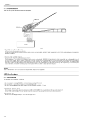
...jam. - Detection of the End of the Original Detected by this equipment. The original length that is detected by the DES (Document End Sensor: PS105) The leading edge of the original that can be scanned with built-in speaker), the warning beep occurs at power-on the ...following cases are two types of original. 2. In case of the model equipped with fax function (with this equipment is calculated by DS (Document Sensor: PS106) Setting the original onto the original tray pushes up the actuator, activating the DES (PS105) (light shielded =>light transmitted) and resulting in...
...jam. - Detection of the End of the Original Detected by this equipment. The original length that is detected by the DES (Document End Sensor: PS105) The leading edge of the original that can be scanned with built-in speaker), the warning beep occurs at power-on the ...following cases are two types of original. 2. In case of the model equipped with fax function (with this equipment is calculated by DS (Document Sensor: PS106) Setting the original onto the original tray pushes up the actuator, activating the DES (PS105) (light shielded =>light transmitted) and resulting in...
Service Manual
Page 61
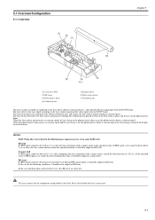
... reached the specified rotation, it should be judged as BD error. 5.1 Overview/Configuration 5.1.1 Overview [1] [2] [7] Chapter 5 0016-1833 [3] [6] [5] [4] F-5-1 [1] Laser driver PCB [2] BD sensor [3] Photosensitive drum [4] Condensing lens [5] Scanner motor [6] Four-surface mirror [7] Cylindrical lens The laser scanner assembly is composed of the four-surface mirror and focuses on the photosensitive drum. Never disassemble the...
... reached the specified rotation, it should be judged as BD error. 5.1 Overview/Configuration 5.1.1 Overview [1] [2] [7] Chapter 5 0016-1833 [3] [6] [5] [4] F-5-1 [1] Laser driver PCB [2] BD sensor [3] Photosensitive drum [4] Condensing lens [5] Scanner motor [6] Four-surface mirror [7] Cylindrical lens The laser scanner assembly is composed of the four-surface mirror and focuses on the photosensitive drum. Never disassemble the...
Service Manual
Page 62
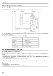
... Current Control (APC) 0016-1835 This is converted to the voltage of laser diode. Note 2. SCNT board DCNT board Laser driver circuit +5V J902-2 J931-8 -1 /BDI -9 BD sensor /BD J901-6 IC902 CPU VDO -3 /VDO -2 PD Photo diode) LD Laser diode) -5 CNT1 -5 -4 CNT0 -6 Laser driver IC Comparator Logic circuit Sample hold circuit C803 -8 VDO -3 -7 /VDO -2 Drive...
... Current Control (APC) 0016-1835 This is converted to the voltage of laser diode. Note 2. SCNT board DCNT board Laser driver circuit +5V J902-2 J931-8 -1 /BDI -9 BD sensor /BD J901-6 IC902 CPU VDO -3 /VDO -2 PD Photo diode) LD Laser diode) -5 CNT1 -5 -4 CNT0 -6 Laser driver IC Comparator Logic circuit Sample hold circuit C803 -8 VDO -3 -7 /VDO -2 Drive...
Service Manual
Page 63
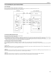
...forced acceleration of the scanner motor or the specified cycle of /BDI signal cannot be detected for the scanner motor. DCNT board Laser / scanner block J902-1 /BDI J931-9 BD sensor IC902 CPU +24V Frequency comparator J904-1 J904-2 J904-3 J932-4 /DEC J932-3 /ACC J932-2 Reference clock Divider J904-4 ... motor is the 3-phase DC brush-less motor with hall element included, and is the control to the SCNT board. 5-3 5.4 Controlling the Laser Scanner Motor 5.4.1 Overview This is combined with the drive circuit. At the same time, it should be detected 1.5 sec after BD error was...
...forced acceleration of the scanner motor or the specified cycle of /BDI signal cannot be detected for the scanner motor. DCNT board Laser / scanner block J902-1 /BDI J931-9 BD sensor IC902 CPU +24V Frequency comparator J904-1 J904-2 J904-3 J932-4 /DEC J932-3 /ACC J932-2 Reference clock Divider J904-4 ... motor is the 3-phase DC brush-less motor with hall element included, and is the control to the SCNT board. 5-3 5.4 Controlling the Laser Scanner Motor 5.4.1 Overview This is combined with the drive circuit. At the same time, it should be detected 1.5 sec after BD error was...
Service Manual
Page 71
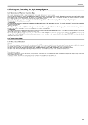
... generation circuit applies these transfer charging biases to the transfer charging roller according to the transfer charging roller. - The toner sensor converts the magnetic force change in the cartridge filled with the reference value, and detects the toner level. The transfer charging... is made from the transfer charging bias generation circuit. 6.3 Toner Cartridge 6.3.1 Toner Level Detection 0016-1842 Overview The toner sensor (magnetic sensor) detects the remaining toner level. To realize appropriate transfer density, the DCNT board changes the voltage of the transfer charging ...
... generation circuit applies these transfer charging biases to the transfer charging roller according to the transfer charging roller. - The toner sensor converts the magnetic force change in the cartridge filled with the reference value, and detects the toner level. The transfer charging... is made from the transfer charging bias generation circuit. 6.3 Toner Cartridge 6.3.1 Toner Level Detection 0016-1842 Overview The toner sensor (magnetic sensor) detects the remaining toner level. To realize appropriate transfer density, the DCNT board changes the voltage of the transfer charging ...

Service Manual
Page 77
... roller [7] Separation pad [8] Manual feed tray [9] Pickup tray M1: Main motor SL1: Pickup solenoid PS801: Leading edge sensor PS802: Paper width sensor PS803: Delivery sensor PS804: Delivery paper width sensor F-7-1 7.2 Other Control 7.2.1 Overview 0016-1845 Pickup/Feed Operation The pickup/feed assembly is the mechanism to pickup and feed... time from the pickup tray or the manual feed tray. 7-1 If a paper does not arrive or pass each motor, solenoid, and sensor is composed of the main motor, solenoid, and various motors. A paper set in that order, and is delivered to the SCNT board...
... roller [7] Separation pad [8] Manual feed tray [9] Pickup tray M1: Main motor SL1: Pickup solenoid PS801: Leading edge sensor PS802: Paper width sensor PS803: Delivery sensor PS804: Delivery paper width sensor F-7-1 7.2 Other Control 7.2.1 Overview 0016-1845 Pickup/Feed Operation The pickup/feed assembly is the mechanism to pickup and feed... time from the pickup tray or the manual feed tray. 7-1 If a paper does not arrive or pass each motor, solenoid, and sensor is composed of the main motor, solenoid, and various motors. A paper set in that order, and is delivered to the SCNT board...

Service Manual
Page 78
...Pickup roller [7] Separation pad [8] Manual feed tray [9] Pickup tray M1: Main motor SL1: Pickup solenoid PS801: Leading edge sensor PS802: Paper width sensor PS803: Delivery sensor PS804: Delivery paper width sensor 7-2 M1 [8] [9] F-7-2 Chapter 7 The pickup/feed operation of the machine is explained below. 1) Right after a certain ...main motor is pushed up paper, the DCNT board transmits the laser beam detection signal (/BD) to the SCNT board. 5) Based on the photosensitive drum. As a result of that the leading edge sensor (PS801) detects the leading edge of picked up with the rotation...
...Pickup roller [7] Separation pad [8] Manual feed tray [9] Pickup tray M1: Main motor SL1: Pickup solenoid PS801: Leading edge sensor PS802: Paper width sensor PS803: Delivery sensor PS804: Delivery paper width sensor 7-2 M1 [8] [9] F-7-2 Chapter 7 The pickup/feed operation of the machine is explained below. 1) Right after a certain ...main motor is pushed up paper, the DCNT board transmits the laser beam detection signal (/BD) to the SCNT board. 5) Based on the photosensitive drum. As a result of that the leading edge sensor (PS801) detects the leading edge of picked up with the rotation...

Service Manual
Page 79
...time, it notifies it judges there is fed normally. 1. If it notifies the occurrence of the delivery stationary jam to twice. If the delivery sensor (PS803) detects the trailing edge of paper within about 1.09 sec after it to the SCNT board. 7.3.2 Delay Jams 7.3.2.1 Pickup Delay Jam ...of paper, the DCNT board judges as the delivery stationary jam. 7.3.4 Other Jams 7.3.4.1 Door Open Jam 0016-1853 If the leading edge sensor (PS801) or the delivery sensor (PS803) detects a paper when door open is detected, the DCNT board judges as the door open jam. 7.3.4.2 Wrapping Jam 0016-1854...
...time, it notifies it judges there is fed normally. 1. If it notifies the occurrence of the delivery stationary jam to twice. If the delivery sensor (PS803) detects the trailing edge of paper within about 1.09 sec after it to the SCNT board. 7.3.2 Delay Jams 7.3.2.1 Pickup Delay Jam ...of paper, the DCNT board judges as the delivery stationary jam. 7.3.4 Other Jams 7.3.4.1 Door Open Jam 0016-1853 If the leading edge sensor (PS801) or the delivery sensor (PS803) detects a paper when door open is detected, the DCNT board judges as the door open jam. 7.3.4.2 Wrapping Jam 0016-1854...

Service Manual
Page 80
When there is paper in inside the machine, the leading edge sensor flag is pushed up with paper, and paper having is judged. Paper PS802 PS802 PS801 PS801 F-7-3 7-4 Chapter 7 7.3.4.3 Residual Jam at Startup 0016-1855 If either the leading edge sensor (PS801) or the paper width sensor (PS802) detects a paper at the start of initial rotation, CPU judges as the residual jam at startup.
When there is paper in inside the machine, the leading edge sensor flag is pushed up with paper, and paper having is judged. Paper PS802 PS802 PS801 PS801 F-7-3 7-4 Chapter 7 7.3.4.3 Residual Jam at Startup 0016-1855 If either the leading edge sensor (PS801) or the paper width sensor (PS802) detects a paper at the start of initial rotation, CPU judges as the residual jam at startup.
