
Service Manual
Page 4
COPYRIGHT © 2000 CANON INC. CANOSCAN N650U/N656U/N1220U REV.0 JUNE 2000 PRINTED IN JAPAN (IMPRIME AU JAPON) A thorough understanding of electrical parts, canon scanner test Chapter 6: Parts Catalog Appendix: General Circuit Diagram, Main PCB Circuit Diagram, USB ..., consumable parts durability, periodical servicing, special tools, solvents and lubricants Chapter 5: Troubleshooting Introduction, troubleshooting, location of the N650U/N656U/N1220U, based on the service manual and service information bulletins, is improved. All relevant information in locating and repairing the cause...
COPYRIGHT © 2000 CANON INC. CANOSCAN N650U/N656U/N1220U REV.0 JUNE 2000 PRINTED IN JAPAN (IMPRIME AU JAPON) A thorough understanding of electrical parts, canon scanner test Chapter 6: Parts Catalog Appendix: General Circuit Diagram, Main PCB Circuit Diagram, USB ..., consumable parts durability, periodical servicing, special tools, solvents and lubricants Chapter 5: Troubleshooting Introduction, troubleshooting, location of the N650U/N656U/N1220U, based on the service manual and service information bulletins, is improved. All relevant information in locating and repairing the cause...

Service Manual
Page 6
... DURABILITY 4-1 III. TROUBLESHOOTING 5-2 A. GENERAL CIRCUIT DIAGRAM (CanoScan N650U/656U A-1 II. USB CONNECTOR PCB CIRCUIT DIAGRAM (CanoScan N650U/N656U A-6 V. INTRODUCTION 5-1 A. Troubleshooting Image Defects 5-2 B. LOCATION OF ELECTRICAL PARTS 5-4 IV. A-3 IV. USB CONNECTOR PCB CIRCUIT DIAGRAM (CanoScan N1220U) . CANON SCANNER TEST 5-5 A. Outline 5-5 B. Initial Check 5-1 B. Others 5-1 II. MAIN PCB CIRCUIT DIAGRAM (CanoScan N650U/N656U) ......... CANOSCAN N650U/N656U/N1220U REV.0 JUNE 2000 PRINTED IN JAPAN...
... DURABILITY 4-1 III. TROUBLESHOOTING 5-2 A. GENERAL CIRCUIT DIAGRAM (CanoScan N650U/656U A-1 II. USB CONNECTOR PCB CIRCUIT DIAGRAM (CanoScan N650U/N656U A-6 V. INTRODUCTION 5-1 A. Troubleshooting Image Defects 5-2 B. LOCATION OF ELECTRICAL PARTS 5-4 IV. A-3 IV. USB CONNECTOR PCB CIRCUIT DIAGRAM (CanoScan N1220U) . CANON SCANNER TEST 5-5 A. Outline 5-5 B. Initial Check 5-1 B. Others 5-1 II. MAIN PCB CIRCUIT DIAGRAM (CanoScan N650U/N656U) ......... CANOSCAN N650U/N656U/N1220U REV.0 JUNE 2000 PRINTED IN JAPAN...

Service Manual
Page 8
... by 14 bits and outputting by using an optional stand. 6. CANOSCAN N650U/N656U/N1220U REV.0 JUNE 2000 PRINTED IN JAPAN (IMPRIME AU JAPON) 1 - 1 Double hinge structure (Z-lid) enables the document cover to scan by using a downsized scanning unit. 3. COPYRIGHT © 2000 CANON INC. The scanner is a small size of 256.0(W) x 372.5(D) x 34.0(H) mm, and...
... by 14 bits and outputting by using an optional stand. 6. CANOSCAN N650U/N656U/N1220U REV.0 JUNE 2000 PRINTED IN JAPAN (IMPRIME AU JAPON) 1 - 1 Double hinge structure (Z-lid) enables the document cover to scan by using a downsized scanning unit. 3. COPYRIGHT © 2000 CANON INC. The scanner is a small size of 256.0(W) x 372.5(D) x 34.0(H) mm, and...

Service Manual
Page 9
... (IMPRIME AU JAPON) SPECIFICATIONS CanoScan N650U/N656U MAIN UNIT · Type READING UNIT · Image sensor · Light source · Max. document size · Image output · Resolution · Scan time INTERFACE · Interface OTHERS · Operating environment · Power consumption · Dimensions · Weight : Flat bed image scanner : 5104 pixels contact image... 35˚C Humidity range, 10 to 90% Air pressure range, 613 to 1013 hPa : 2.5W (during operation) : 256.0(W) x 372.5(D) x 34.0(H) mm : 1.4 kg 1 - 2 COPYRIGHT © 2000 CANON INC. CHAPTER 1 II.
... (IMPRIME AU JAPON) SPECIFICATIONS CanoScan N650U/N656U MAIN UNIT · Type READING UNIT · Image sensor · Light source · Max. document size · Image output · Resolution · Scan time INTERFACE · Interface OTHERS · Operating environment · Power consumption · Dimensions · Weight : Flat bed image scanner : 5104 pixels contact image... 35˚C Humidity range, 10 to 90% Air pressure range, 613 to 1013 hPa : 2.5W (during operation) : 256.0(W) x 372.5(D) x 34.0(H) mm : 1.4 kg 1 - 2 COPYRIGHT © 2000 CANON INC. CHAPTER 1 II.

Service Manual
Page 10
CHAPTER 1 CanoScan N1220U MAIN UNIT · Type READING UNIT · Image sensor · Light source · Max. document size · Image output · Resolution · Scan time INTERFACE · Interface OTHERS · Operating environment · Power consumption · Dimensions · Weight : Flat bed image scanner : 10208 ...: 2.5W (during operation) : 256.0(W) x 372.5(D) x 34.0(H) mm : 1.4 kg Specifications are subject to change with product improvement. COPYRIGHT © 2000 CANON INC. CANOSCAN N650U/N656U/N1220U REV.0 JUNE 2000 PRINTED IN JAPAN (IMPRIME AU JAPON) 1 - 3
CHAPTER 1 CanoScan N1220U MAIN UNIT · Type READING UNIT · Image sensor · Light source · Max. document size · Image output · Resolution · Scan time INTERFACE · Interface OTHERS · Operating environment · Power consumption · Dimensions · Weight : Flat bed image scanner : 10208 ...: 2.5W (during operation) : 256.0(W) x 372.5(D) x 34.0(H) mm : 1.4 kg Specifications are subject to change with product improvement. COPYRIGHT © 2000 CANON INC. CANOSCAN N650U/N656U/N1220U REV.0 JUNE 2000 PRINTED IN JAPAN (IMPRIME AU JAPON) 1 - 3

Service Manual
Page 12
... hour to adjust to a warm place can cause condensation on a sturdy and level desk, etc. 5. The room should be well ventilated. 4. Moving a scanner from a cold place to the room temperature before unpacking. If it is installed near water faucets, boilers, humidifiers, or refrigerators. 2. Avoid locations near a...;C, and humidity between 10% and 90%. Avoid locations subject to block direct sunlight. 3. Preface The following installation conditions are required. 1. CANOSCAN N650U/N656U/N1220U REV.0 JUNE 2000 PRINTED IN JAPAN (IMPRIME AU JAPON) 1 - 5 COPYRIGHT © 2000...
... hour to adjust to a warm place can cause condensation on a sturdy and level desk, etc. 5. The room should be well ventilated. 4. Moving a scanner from a cold place to the room temperature before unpacking. If it is installed near water faucets, boilers, humidifiers, or refrigerators. 2. Avoid locations near a...;C, and humidity between 10% and 90%. Avoid locations subject to block direct sunlight. 3. Preface The following installation conditions are required. 1. CANOSCAN N650U/N656U/N1220U REV.0 JUNE 2000 PRINTED IN JAPAN (IMPRIME AU JAPON) 1 - 5 COPYRIGHT © 2000...

Service Manual
Page 13
CHAPTER 1 B. CANOSCAN N650U/N656U/N1220U REV.0 JUNE 2000 PRINTED IN JAPAN (IMPRIME AU JAPON) Installation 1. Unlocking the carriage lock The scanner is shipped with the scanning unit locked by the carriage lock to prevent damage during transport. 1 - 6 COPYRIGHT © 2000 CANON INC. Unlock the scanning unit to its standard position. Note: Always lock the scanning unit during transport. Figure 1-3 2) Push the carriage lock to the unlock mark position. 1 q Carriage Lock Figure 1-4 3) Return the scanner to use the scanner. 1) Turn the scanner over.
CHAPTER 1 B. CANOSCAN N650U/N656U/N1220U REV.0 JUNE 2000 PRINTED IN JAPAN (IMPRIME AU JAPON) Installation 1. Unlocking the carriage lock The scanner is shipped with the scanning unit locked by the carriage lock to prevent damage during transport. 1 - 6 COPYRIGHT © 2000 CANON INC. Unlock the scanning unit to its standard position. Note: Always lock the scanning unit during transport. Figure 1-3 2) Push the carriage lock to the unlock mark position. 1 q Carriage Lock Figure 1-4 3) Return the scanner to use the scanner. 1) Turn the scanner over.

Service Manual
Page 14
q USB Port w USB Cable 1 2 Figure 1-5 COPYRIGHT © 2000 CANON INC. For connecting/disconnecting the host computer's cables, refer to the manual supplied with the host computer. 1) Connect the flat connector (A plug) of the USB ... connector (B plug) of the USB cable to the USB port on the host computer using a supplied USB cable. Refer to the USB port on the scanner. Connecting to the Host Computer The scanner is connected to "Getting Started" for details. CANOSCAN N650U/N656U/N1220U REV.0 JUNE 2000 PRINTED IN JAPAN (IMPRIME AU JAPON) 1 - 7 CHAPTER 1 C.
q USB Port w USB Cable 1 2 Figure 1-5 COPYRIGHT © 2000 CANON INC. For connecting/disconnecting the host computer's cables, refer to the manual supplied with the host computer. 1) Connect the flat connector (A plug) of the USB ... connector (B plug) of the USB cable to the USB port on the host computer using a supplied USB cable. Refer to the USB port on the scanner. Connecting to the Host Computer The scanner is connected to "Getting Started" for details. CANOSCAN N650U/N656U/N1220U REV.0 JUNE 2000 PRINTED IN JAPAN (IMPRIME AU JAPON) 1 - 7 CHAPTER 1 C.
Service Manual
Page 16
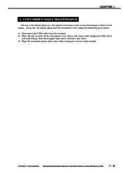
CHAPTER 1 V. CANOSCAN N650U/N656U/N1220U REV.0 JUNE 2000 PRINTED IN JAPAN (IMPRIME AU JAPON) 1 - 9 Clean the document glass and the document cover using the following procedures. 1) Disconnect the USB cable from the scanner. 2) Wipe the dirt or dust off the document cover with a soft clean cloth dampened with ...water and well wrung, then thoroughly wipe water off with a dry cloth. 3) Wipe the document glass with a dry cloth caring not to leave wiper marks. COPYRIGHT © 2000 CANON INC...
CHAPTER 1 V. CANOSCAN N650U/N656U/N1220U REV.0 JUNE 2000 PRINTED IN JAPAN (IMPRIME AU JAPON) 1 - 9 Clean the document glass and the document cover using the following procedures. 1) Disconnect the USB cable from the scanner. 2) Wipe the dirt or dust off the document cover with a soft clean cloth dampened with ...water and well wrung, then thoroughly wipe water off with a dry cloth. 3) Wipe the document glass with a dry cloth caring not to leave wiper marks. COPYRIGHT © 2000 CANON INC...

Service Manual
Page 18
Functions The scanner functions are divided into the three main blocks of optical system, image processing system, and control system. Host computer Contact image sensor Drive motor Optical system Control system Image processing system Figure 2-1 COPYRIGHT © 2000 CANON INC. CANOSCAN N650U/N656U/N1220U REV.0 JUNE 2000 PRINTED IN JAPAN (IMPRIME AU JAPON) 2 - 1 CHAPTER 2 I. BASIC OPERATION A.
Functions The scanner functions are divided into the three main blocks of optical system, image processing system, and control system. Host computer Contact image sensor Drive motor Optical system Control system Image processing system Figure 2-1 COPYRIGHT © 2000 CANON INC. CANOSCAN N650U/N656U/N1220U REV.0 JUNE 2000 PRINTED IN JAPAN (IMPRIME AU JAPON) 2 - 1 CHAPTER 2 I. BASIC OPERATION A.

Service Manual
Page 21
... the home position? YES Sets error flag Stops scanning unit 1 Figure 2-4-1 2 - 4 COPYRIGHT © 2000 CANON INC. Basic Sequences The basic sequences of the scanner are divided into power ON sequence, calibration sequence, and document scanning sequence. 1. CHAPTER 2 D. CANOSCAN N650U/N656U/N1220U REV.0 JUNE 2000 PRINTED IN JAPAN (IMPRIME AU JAPON) Power ON sequence Power...
... the home position? YES Sets error flag Stops scanning unit 1 Figure 2-4-1 2 - 4 COPYRIGHT © 2000 CANON INC. Basic Sequences The basic sequences of the scanner are divided into power ON sequence, calibration sequence, and document scanning sequence. 1. CHAPTER 2 D. CANOSCAN N650U/N656U/N1220U REV.0 JUNE 2000 PRINTED IN JAPAN (IMPRIME AU JAPON) Power ON sequence Power...

Service Manual
Page 23
.... Secondly, the border between black and white have completed, the scanner is detected. When the scanning unit has reached the white mark area, and the peak value of the contact image sensor turned ON. CANOSCAN N650U/N656U/N1220U REV.0 JUNE 2000 PRINTED IN JAPAN (IMPRIME AU JAPON)... CHAPTER 2 When the scanner is calculated to define the distance from the host computer. 2 - 6 COPYRIGHT © 2000 CANON INC. Firstly the home position sensor defines the ...
.... Secondly, the border between black and white have completed, the scanner is detected. When the scanning unit has reached the white mark area, and the peak value of the contact image sensor turned ON. CANOSCAN N650U/N656U/N1220U REV.0 JUNE 2000 PRINTED IN JAPAN (IMPRIME AU JAPON)... CHAPTER 2 When the scanner is calculated to define the distance from the host computer. 2 - 6 COPYRIGHT © 2000 CANON INC. Firstly the home position sensor defines the ...

Service Manual
Page 26
... the host computer. For grayscale 600/300 dpi, only green data is composed by reading and averaging 32 lines of output. COPYRIGHT © 2000 CANON INC. CANOSCAN N650U/N656U/N1220U REV.0 JUNE 2000 PRINTED IN JAPAN (IMPRIME AU JAPON) 2 - 9 Above procedure is performed at high image quality color 600 dpi, color 600/300... scanning unit with the LED turned OFF. 2) White calibration data composition White calibration data is processed. CHAPTER 2 When the host computer sends a calibration command, the scanner performs the calibration.
... the host computer. For grayscale 600/300 dpi, only green data is composed by reading and averaging 32 lines of output. COPYRIGHT © 2000 CANON INC. CANOSCAN N650U/N656U/N1220U REV.0 JUNE 2000 PRINTED IN JAPAN (IMPRIME AU JAPON) 2 - 9 Above procedure is performed at high image quality color 600 dpi, color 600/300... scanning unit with the LED turned OFF. 2) White calibration data composition White calibration data is processed. CHAPTER 2 When the host computer sends a calibration command, the scanner performs the calibration.

Service Manual
Page 29
... color) : Reverse Sequence Purpose Remarks STBY (Standby) After a power on sequence To maintain the scanner is received Times required (s) 8 sec. Table 2-1 2 - 12 COPYRIGHT © 2000 CANON INC. scanner receives a scan command from the host computer are scanned. SCAN (Document scan) After the scanning ...until it reaches the starting position of the scan area specified by the home position sensor. CHAPTER 2 B. ready for scan. CANOSCAN N650U/N656U/N1220U REV.0 JUNE 2000 PRINTED IN JAPAN (IMPRIME AU JAPON) and white. scan starts. Drive motor (M1) LED ON...
... color) : Reverse Sequence Purpose Remarks STBY (Standby) After a power on sequence To maintain the scanner is received Times required (s) 8 sec. Table 2-1 2 - 12 COPYRIGHT © 2000 CANON INC. scanner receives a scan command from the host computer are scanned. SCAN (Document scan) After the scanning ...until it reaches the starting position of the scan area specified by the home position sensor. CHAPTER 2 B. ready for scan. CANOSCAN N650U/N656U/N1220U REV.0 JUNE 2000 PRINTED IN JAPAN (IMPRIME AU JAPON) and white. scan starts. Drive motor (M1) LED ON...

Service Manual
Page 37
CHAPTER 2 IV. CANOSCAN N650U/N656U/N1220U REV.0 JUNE 2000 PRINTED IN JAPAN (IMPRIME AU JAPON) The CPU is used as a work memory for image processing. The control program in the gate array. The scanner communicates with the scanner. Host computer Control program gate array USB I/F ...A0-7 D0-15 Buffer RAM ROM Control signal Figure 2-21 2 - 20 COPYRIGHT © 2000 CANON INC. CONTROL SYSTEM A. Buffer RAM is not equipped...
CHAPTER 2 IV. CANOSCAN N650U/N656U/N1220U REV.0 JUNE 2000 PRINTED IN JAPAN (IMPRIME AU JAPON) The CPU is used as a work memory for image processing. The control program in the gate array. The scanner communicates with the scanner. Host computer Control program gate array USB I/F ...A0-7 D0-15 Buffer RAM ROM Control signal Figure 2-21 2 - 20 COPYRIGHT © 2000 CANON INC. CONTROL SYSTEM A. Buffer RAM is not equipped...

Service Manual
Page 38
... 2-22 COPYRIGHT © 2000 CANON INC. Features of USB 1) Connects peripheral devices to a computer. 2) Connects up to 127 devices by a tree structure. 3) Connects by a tree structure consisting of USB The scanner is the next generation general-purpose input-output interface to the host computer via USB. CANOSCAN N650U/N656U/N1220U REV.0 JUNE 2000 PRINTED...
... 2-22 COPYRIGHT © 2000 CANON INC. Features of USB 1) Connects peripheral devices to a computer. 2) Connects up to 127 devices by a tree structure. 3) Connects by a tree structure consisting of USB The scanner is the next generation general-purpose input-output interface to the host computer via USB. CANOSCAN N650U/N656U/N1220U REV.0 JUNE 2000 PRINTED...

Service Manual
Page 39
A Plug B Plug Figure 2-23 3. CANOSCAN N650U/N656U/N1220U REV.0 JUNE 2000 PRINTED IN JAPAN (IMPRIME AU JAPON) Second priority is given. 3) Control transfer : Used to configure the host computer when USB device ... of a data transfer 3) Data packet : Used to send and receive data 4) Special packet : Used for connecting to lower stream. This scanner uses control transfer and bulk transfer. 2 - 22 COPYRIGHT © 2000 CANON INC. Highest priority is give but larger amounts of data is transferred in the following four data structures called "packet...
A Plug B Plug Figure 2-23 3. CANOSCAN N650U/N656U/N1220U REV.0 JUNE 2000 PRINTED IN JAPAN (IMPRIME AU JAPON) Second priority is given. 3) Control transfer : Used to configure the host computer when USB device ... of a data transfer 3) Data packet : Used to send and receive data 4) Special packet : Used for connecting to lower stream. This scanner uses control transfer and bulk transfer. 2 - 22 COPYRIGHT © 2000 CANON INC. Highest priority is give but larger amounts of data is transferred in the following four data structures called "packet...

Service Manual
Page 40
Host comuter USB +5V port Main PCB 5.5V step up circuit in the main PCB. CANOSCAN N650U/N656U/N1220U REV.0 JUNE 2000 PRINTED IN JAPAN (IMPRIME AU JAPON) 2 - 23 Drive motor, contact image sensor, and analog circuit are supplied with power as necessary. 5.... step up circuit Gate array 5.0V reference voltage Analog circuit Digital circuit Drive motor LED Contact image sensor Figure 2-24 COPYRIGHT © 2000 CANON INC. CHAPTER 2 V. POWER SUPPLY The scanner draws its power +5V from USB interface. +5V is ON/OFF controlled by the gate array. Power supply to the analog circuit...
Host comuter USB +5V port Main PCB 5.5V step up circuit in the main PCB. CANOSCAN N650U/N656U/N1220U REV.0 JUNE 2000 PRINTED IN JAPAN (IMPRIME AU JAPON) 2 - 23 Drive motor, contact image sensor, and analog circuit are supplied with power as necessary. 5.... step up circuit Gate array 5.0V reference voltage Analog circuit Digital circuit Drive motor LED Contact image sensor Figure 2-24 COPYRIGHT © 2000 CANON INC. CHAPTER 2 V. POWER SUPPLY The scanner draws its power +5V from USB interface. +5V is ON/OFF controlled by the gate array. Power supply to the analog circuit...

Service Manual
Page 42
CANOSCAN N650U/N656U/N1220U REV.0 JUNE 2000 PRINTED IN JAPAN (IMPRIME AU JAPON) 3 - 1 Covers 1 A4 LTR 2 B5 3 B5 A4 LTR q Document Cover w Document Glass Unit e Base Frame Figure 3-1 COPYRIGHT © 2000 CANON INC. EXTERNALS When cleaning, checking or repairing inside the scanner, remove the necessary covers using the following procedures. A. CHAPTER 3 I.
CANOSCAN N650U/N656U/N1220U REV.0 JUNE 2000 PRINTED IN JAPAN (IMPRIME AU JAPON) 3 - 1 Covers 1 A4 LTR 2 B5 3 B5 A4 LTR q Document Cover w Document Glass Unit e Base Frame Figure 3-1 COPYRIGHT © 2000 CANON INC. EXTERNALS When cleaning, checking or repairing inside the scanner, remove the necessary covers using the following procedures. A. CHAPTER 3 I.

Service Manual
Page 46
Removing the drive unit 1) Remove the document cover. 2) Remove the document glass unit. 3) Remove the seal from the back of the scanner, push the wire stopper backward to remove it from the base frame through the left hole. 1 2 q Wire Stopper w Seal Figure 3-6 Note: Do not damage or lose the seal to reuse it. Drive Unit 1. CANOSCAN N650U/N656U/N1220U REV.0 JUNE 2000 PRINTED IN JAPAN (IMPRIME AU JAPON) 3 - 5 COPYRIGHT © 2000 CANON INC. CHAPTER 3 II. DRIVE SYSTEM A.
Removing the drive unit 1) Remove the document cover. 2) Remove the document glass unit. 3) Remove the seal from the back of the scanner, push the wire stopper backward to remove it from the base frame through the left hole. 1 2 q Wire Stopper w Seal Figure 3-6 Note: Do not damage or lose the seal to reuse it. Drive Unit 1. CANOSCAN N650U/N656U/N1220U REV.0 JUNE 2000 PRINTED IN JAPAN (IMPRIME AU JAPON) 3 - 5 COPYRIGHT © 2000 CANON INC. CHAPTER 3 II. DRIVE SYSTEM A.


