CS300 Silicon Pyranometer
Page 2
... US and International customers residing in it. Campbell Scientific, Inc.'s obligation under normal use and service for special, indirect, incidental, or consequential damages. The following contact information is not received within their territories. Warranty and Assistance The CS300 PYRANOMETER is : CAMPBELL SCIENTIFIC, INC. Campbell Scientific, Inc. To obtain a Returned Materials Authorization (RMA), contact Campbell Scientific, Inc., phone (435) 753-2342. A completed form must fill...
... US and International customers residing in it. Campbell Scientific, Inc.'s obligation under normal use and service for special, indirect, incidental, or consequential damages. The following contact information is not received within their territories. Warranty and Assistance The CS300 PYRANOMETER is : CAMPBELL SCIENTIFIC, INC. Campbell Scientific, Inc. To obtain a Returned Materials Authorization (RMA), contact Campbell Scientific, Inc., phone (435) 753-2342. A completed form must fill...
CS300 Silicon Pyranometer
Page 3
... Pyranometer Mounting Arm 3 4-1. General Description 1 2. Multipliers Required for Example Programs 5 i CS300 Table of Contents PDF viewers note: These page numbers refer to Campbell Scientific Dataloggers 4 5-1. Wiring for Average Flux and Total Flux Density in SI and English Units 5 5-2. Wiring 4 5. Connections to the printed version of this document. Use the Adobe Acrobat® bookmarks tab for links to specific sections. 1. Troubleshooting 9 Figures 3-1. CS300 Schematic 4 Tables 4-1. Programming 4 5.1 Example Programs 5 5.1.1 CR1000 Example Program...
... Pyranometer Mounting Arm 3 4-1. General Description 1 2. Multipliers Required for Example Programs 5 i CS300 Table of Contents PDF viewers note: These page numbers refer to Campbell Scientific Dataloggers 4 5-1. Wiring for Average Flux and Total Flux Density in SI and English Units 5 5-2. Wiring 4 5. Connections to the printed version of this document. Use the Adobe Acrobat® bookmarks tab for links to specific sections. 1. Troubleshooting 9 Figures 3-1. CS300 Schematic 4 Tables 4-1. Programming 4 5.1 Example Programs 5 5.1.1 CR1000 Example Program...
CS300 Silicon Pyranometer
Page 5
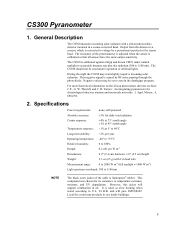
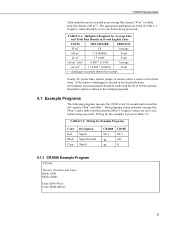
... the potentiometer is adjusted when the sensor is calibrated against a Kipp and Zonen CM21 under vegetation or artificial lights. W. B. During the night the CS300 may be used under natural sunlight to accurately measure sun plus sky radiation (300 to zero in a cosine-corrected head. Specifications Power requirements: none, self-powered Absolute accuracy: ±5% for climatological observer stations and mesoscale...
... the potentiometer is adjusted when the sensor is calibrated against a Kipp and Zonen CM21 under vegetation or artificial lights. W. B. During the night the CS300 may be used under natural sunlight to accurately measure sun plus sky radiation (300 to zero in a cosine-corrected head. Specifications Power requirements: none, self-powered Absolute accuracy: ±5% for climatological observer stations and mesoscale...
CS300 Silicon Pyranometer
Page 6
... should be mounted with the cable pointing towards the nearest magnetic pole, e.g., in their cable that it is not critical for shipping or storing the sensor. 2 Mounting height is never shaded by the tripod/tower or other sensors. Installation The CS300 should be mounted such that contains a circuit board (located 18" from direct sunlight. However, pyranometers mounted at heights...
... should be mounted with the cable pointing towards the nearest magnetic pole, e.g., in their cable that it is not critical for shipping or storing the sensor. 2 Mounting height is never shaded by the tripod/tower or other sensors. Installation The CS300 should be mounted such that contains a circuit board (located 18" from direct sunlight. However, pyranometers mounted at heights...
CS300 Silicon Pyranometer
Page 7
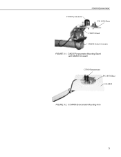
CS300 Pyranometer CS300 Pyranometer PN 18356 Base CM225 Stand CM200 Series Crossarm FIGURE 3-1. CM225 Pyranometer Mounting Stand and CM202 Crossarm CS300 Pyranometer PN 18356 Base 015ARM FIGURE 3-2. 015ARM Pyranometer Mounting Arm 3
CS300 Pyranometer CS300 Pyranometer PN 18356 Base CM225 Stand CM200 Series Crossarm FIGURE 3-1. CM225 Pyranometer Mounting Stand and CM202 Crossarm CS300 Pyranometer PN 18356 Base 015ARM FIGURE 3-2. 015ARM Pyranometer Mounting Arm 3
CS300 Silicon Pyranometer
Page 8
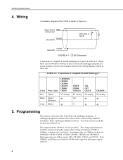
... Figure 4-1. TABLE 4-1. CS300 Schematic Connections to use CRBasic include the CR200(X), CR800, CR850, CR1000, CR3000, CR5000, and CR9000(X). Connections to 600 Ω typical CLEAR Ground/G FIGURE 4-1. Dataloggers that use Edlog include CR7, CR10(X), CR510, and CR23X. Programming This section is measured using Campbell Scientific's Short Cut Program Builder software. Single-Ended RED Analog Input BLACK Ground/AG 500 to Campbell Scientific Dataloggers Color Red Black Clear Wire Label Signal Signal Reference Shield...
... Figure 4-1. TABLE 4-1. CS300 Schematic Connections to use CRBasic include the CR200(X), CR800, CR850, CR1000, CR3000, CR5000, and CR9000(X). Connections to 600 Ω typical CLEAR Ground/G FIGURE 4-1. Dataloggers that use Edlog include CR7, CR10(X), CR510, and CR23X. Programming This section is measured using Campbell Scientific's Short Cut Program Builder software. Single-Ended RED Analog Input BLACK Ground/AG 500 to Campbell Scientific Dataloggers Color Red Black Clear Wire Label Signal Signal Reference Shield...
CS300 Silicon Pyranometer
Page 9
... in an electrically noisy environment, the measurement should be set to zero before being processed. CS300 Pyranometer Solar radiation can be a source of electrical noise. Wiring for Example Programs Color Red Black Clear Description Signal Signal Ground Shield CR1000 SE 1 CR10X SE 1 AG G 5.1.1 CR1000 Example Program 'CR1000 'Declare Variables and Units Public SlrW Public SlrMJ Units SlrW=W/m² Units SlrMJ=MJ/m² 5
... in an electrically noisy environment, the measurement should be set to zero before being processed. CS300 Pyranometer Solar radiation can be a source of electrical noise. Wiring for Example Programs Color Red Black Clear Description Signal Signal Ground Shield CR1000 SE 1 CR10X SE 1 AG G 5.1.1 CR1000 Example Program 'CR1000 'Declare Variables and Units Public SlrW Public SlrMJ Units SlrW=W/m² Units SlrMJ=MJ/m² 5
CS300 Silicon Pyranometer
Page 10
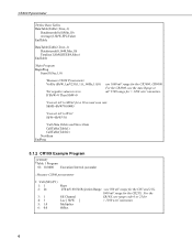
... 60 Hz Rejection Range ; use range code 0 or 25 for > 1200 w/m2 intensities. Multiplier Offset 6 CS300 Pyranometer 'Define Data Tables DataTable(Table1,True,-1) DataInterval(0,60,Min,10) Average(1,SlrW,FP2,False) EndTable DataTable(Table2,True,-1) DataInterval(0,1440,Min,10) Totalize(1,SlrMJ,IEEE4,False) EndTable 'Main Program BeginProg Scan(10,Sec,1,0) 'Measure CS300 Pyranometer VoltSe (SlrW,1,mV250,1,1,0,_60Hz,1.0,0) 'Set negative values...
... 60 Hz Rejection Range ; use range code 0 or 25 for > 1200 w/m2 intensities. Multiplier Offset 6 CS300 Pyranometer 'Define Data Tables DataTable(Table1,True,-1) DataInterval(0,60,Min,10) Average(1,SlrW,FP2,False) EndTable DataTable(Table2,True,-1) DataInterval(0,1440,Min,10) Totalize(1,SlrMJ,IEEE4,False) EndTable 'Main Program BeginProg Scan(10,Sec,1,0) 'Measure CS300 Pyranometer VoltSe (SlrW,1,mV250,1,1,0,_60Hz,1.0,0) 'Set negative values...
CS300 Silicon Pyranometer
Page 11
... [ SlrW ] 2: 5 F 3: 1 Z Loc [ SlrW ] 7: If time is (P92) 1: 0 Minutes (Seconds --) into a 2: 60 Interval (same units as above) 3: 10 Set Output Flag High (Flag 0) 8: Set Active Storage Area (P80) 1: 1 Final Storage Area 1 2: 101 Array ID 9: Real Time (P77) 1: 1220 Year,Day,Hour/Minute (midnight = 2400) 10: Average (...P71) 1: 1 Reps 2: 1 Loc [ SlrW ] 11: If time is (P92) 1: 0 Minutes (Seconds --) into a 2: 1440 Interval (same units as above) 3: 10 Set Output Flag High (Flag 0) 12: Set ...
... [ SlrW ] 2: 5 F 3: 1 Z Loc [ SlrW ] 7: If time is (P92) 1: 0 Minutes (Seconds --) into a 2: 60 Interval (same units as above) 3: 10 Set Output Flag High (Flag 0) 8: Set Active Storage Area (P80) 1: 1 Final Storage Area 1 2: 101 Array ID 9: Real Time (P77) 1: 1220 Year,Day,Hour/Minute (midnight = 2400) 10: Average (...P71) 1: 1 Reps 2: 1 Loc [ SlrW ] 11: If time is (P92) 1: 0 Minutes (Seconds --) into a 2: 1440 Interval (same units as above) 3: 10 Set Output Flag High (Flag 0) 12: Set ...
CS300 Silicon Pyranometer
Page 12
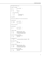
...the maximum flux density the datalogger can be checked. Another alternative for Edlog dataloggers, record an average flux. CS300 Pyranometer 13: Real Time (P77) 1: 1220 Year,Day,Hour/Minute (midnight = 2400) 14: Resolution (...output interval to arrive at a output interval flux density. CAUTION Handle the sensor carefully when cleaning. Instruction 78 is used to switch to find a daily total flux density. Maintenance and Calibration On a monthly basis the level of the pyranometer should be exceeded in low resolution and dividing by the number of seconds in units...
...the maximum flux density the datalogger can be checked. Another alternative for Edlog dataloggers, record an average flux. CS300 Pyranometer 13: Real Time (P77) 1: 1220 Year,Day,Hour/Minute (midnight = 2400) 14: Resolution (...output interval to arrive at a output interval flux density. CAUTION Handle the sensor carefully when cleaning. Instruction 78 is used to switch to find a daily total flux density. Maintenance and Calibration On a monthly basis the level of the pyranometer should be exceeded in low resolution and dividing by the number of seconds in units...
CS300 Silicon Pyranometer
Page 13
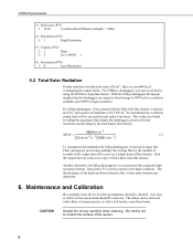
... the red (+) and the black (-) wires. The voltage should be serviced. Obtain an RMA number before returning the CS300 to 1000 Wm-2 radiation. Check that the Range code is properly leveled. 2. Troubleshooting Symptom: -9999 or radiation values around 0 1. Disconnect the sensor leads from the datalogger and use a DVM to the Single-Ended channel specified by the measurement instruction. 2. No voltage indicates a problem with...
... the red (+) and the black (-) wires. The voltage should be serviced. Obtain an RMA number before returning the CS300 to 1000 Wm-2 radiation. Check that the Range code is properly leveled. 2. Troubleshooting Symptom: -9999 or radiation values around 0 1. Disconnect the sensor leads from the datalogger and use a DVM to the Single-Ended channel specified by the measurement instruction. 2. No voltage indicates a problem with...
