
Service Manual
Page 11
Custom size (2.75x5, 8.5x14) Envelop (DL/C5/CM10/Mona) Support Windows OS (Printer Driver) - ADF (pages) - - Windows GDI (600x600) Memory (Typical) - 1 MB Memory (MIN.) - 600 KB Fonts Resident - - Period to go in Sleep Mode 0-99 0-...
Custom size (2.75x5, 8.5x14) Envelop (DL/C5/CM10/Mona) Support Windows OS (Printer Driver) - ADF (pages) - - Windows GDI (600x600) Memory (Typical) - 1 MB Memory (MIN.) - 600 KB Fonts Resident - - Period to go in Sleep Mode 0-99 0-...

Service Manual
Page 41
... and Control Panel (1) Place the control panel ASSY upside down. The spring also comes off. (5) To remove the document rear sensor actuator, pull either of supports "b" on the panel rear cover outwards and then lift the pressure bar up and towards the rear to step (6). (2) To remove the ADF parts (spring..., or document rear sensor actuator, skip to release the three tabs from the cutouts provided in . (4) To remove the document pressure bar, pull either of supports "a" provided on the panel rear cover outwards.
... and Control Panel (1) Place the control panel ASSY upside down. The spring also comes off. (5) To remove the document rear sensor actuator, pull either of supports "b" on the panel rear cover outwards and then lift the pressure bar up and towards the rear to step (6). (2) To remove the ADF parts (spring..., or document rear sensor actuator, skip to release the three tabs from the cutouts provided in . (4) To remove the document pressure bar, pull either of supports "a" provided on the panel rear cover outwards.

Service Manual
Page 53
(5) Remove the four screws from the hinges R and L. (6) Slightly lift up the top cover to release the bosses from the hinges and take it off to the rear. (7) Remove the harness support sponges and take out the harnesses from the top cover. IV - 21
(5) Remove the four screws from the hinges R and L. (6) Slightly lift up the top cover to release the bosses from the hinges and take it off to the rear. (7) Remove the harness support sponges and take out the harnesses from the top cover. IV - 21

Service Manual
Page 54
... each hinge back into place, fit its tab in . Reassembling Notes • When setting each of the main cover, and then fix them with the support sponge. Route the panel-main harness and CIS harness through hooks "B1" of the top cover and through hooks "B2" of the main cover, and... then fix them with the support sponge. • When connecting the scanner motor harness to the scanner motor connector, take care not to bend the shield film. • Once removed, the...
... each hinge back into place, fit its tab in . Reassembling Notes • When setting each of the main cover, and then fix them with the support sponge. Route the panel-main harness and CIS harness through hooks "B1" of the top cover and through hooks "B2" of the main cover, and... then fix them with the support sponge. • When connecting the scanner motor harness to the scanner motor connector, take care not to bend the shield film. • Once removed, the...

Service Manual
Page 67
1.16 Fan (1) If the main PCB is installed, remove the screw from the main PCB (refer to Section 1.14). (2) Slightly lift up the main PCB and disconnect the fan harness from the main PCB. (3) Take out the fan support. (4) Pull up and with the non-sponge end facing up the fan. IV - 35 Reassembling Notes • Put the fan back into place with the label side facing outwards. • Route the fan harness through the harness guide as shown above.
1.16 Fan (1) If the main PCB is installed, remove the screw from the main PCB (refer to Section 1.14). (2) Slightly lift up the main PCB and disconnect the fan harness from the main PCB. (3) Take out the fan support. (4) Pull up and with the non-sponge end facing up the fan. IV - 35 Reassembling Notes • Put the fan back into place with the label side facing outwards. • Route the fan harness through the harness guide as shown above.
Service Manual
Page 95
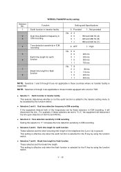
... ms : 700 ms : 80 ms : 110 ms : 250 ms : 500 ms NOTE: Selectors 1 and 5 through 4 are applicable to those countries where no transfer facility is supported. Selector 1: Earth function in transfer facility This selector determines whether or not the earth function is added to the transfer setting menu to be accessed...
... ms : 700 ms : 80 ms : 110 ms : 250 ms : 500 ms NOTE: Selectors 1 and 5 through 4 are applicable to those countries where no transfer facility is supported. Selector 1: Earth function in transfer facility This selector determines whether or not the earth function is added to the transfer setting menu to be accessed...

Service Manual
Page 96
...WAIT (3.5, 7.0, 10.5, 14.0, 17.5, 21.0, or 24.5 seconds) without detection of a dial tone when a line is supported. pause time allowable for remote ID code detection This selector sets the maximum pause time allowable for remote ID code detection Busy ... dialing 0 : Yes 1: No NOTE: Selectors 5 through 3: 1st dial tone detection These selectors activate or deactivate the 1st dial tone detection function which support no busy tone detection is connected. (However, in those countries where no dial tone detection function, e.g., in automatic receiving mode Not used. Selector No....
...WAIT (3.5, 7.0, 10.5, 14.0, 17.5, 21.0, or 24.5 seconds) without detection of a dial tone when a line is supported. pause time allowable for remote ID code detection This selector sets the maximum pause time allowable for remote ID code detection Busy ... dialing 0 : Yes 1: No NOTE: Selectors 5 through 3: 1st dial tone detection These selectors activate or deactivate the 1st dial tone detection function which support no busy tone detection is connected. (However, in those countries where no dial tone detection function, e.g., in automatic receiving mode Not used. Selector No....

Service Manual
Page 97
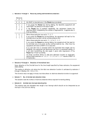
... detection in automatic receiving mode This selector determines whether or not the equipment automatically disconnects a line upon detection of a busy tone in those countries not supporting the dial tone detection (e.g., U.S.A.). Setting both of a busy tone in automatic receiving mode.
... detection in automatic receiving mode This selector determines whether or not the equipment automatically disconnects a line upon detection of a busy tone in those countries not supporting the dial tone detection (e.g., U.S.A.). Setting both of a busy tone in automatic receiving mode.

Service Manual
Page 98
... dial tone interrupt detecting time 0: 30 ms 1: 50 ms NOTE: Selectors 4 through 8 are not applicable in DP and push-button (PB) dialing system Detection of international tone No. 4 5 6 0 0 0 : 50 ms 0 0 1 : 210 ms 0 1 0 : 500 ms 0 1 1 : 800 ms 1 0 0 : 900 ms 1 0 1 : 1.5 sec. 1 1 0 : 2.0 sec. 1 1 1 : 2.5 sec. WAIT 7 sec..... WAIT 2nd dial tone detection only in pulse dialing (DP) system 2nd dial tone detection both in those countries where no dial tone detection is supported, e.g., U.S.A. WAIT 14 sec. WSW06 (Pause key setting and 2nd dial tone detection) Selector No. 1 | 3 4 | 6 7 8 ...
... dial tone interrupt detecting time 0: 30 ms 1: 50 ms NOTE: Selectors 4 through 8 are not applicable in DP and push-button (PB) dialing system Detection of international tone No. 4 5 6 0 0 0 : 50 ms 0 0 1 : 210 ms 0 1 0 : 500 ms 0 1 1 : 800 ms 1 0 0 : 900 ms 1 0 1 : 1.5 sec. 1 1 0 : 2.0 sec. 1 1 1 : 2.5 sec. WAIT 7 sec..... WAIT 2nd dial tone detection only in pulse dialing (DP) system 2nd dial tone detection both in those countries where no dial tone detection is supported, e.g., U.S.A. WAIT 14 sec. WSW06 (Pause key setting and 2nd dial tone detection) Selector No. 1 | 3 4 | 6 7 8 ...
Service Manual
Page 99
... these selectors to "1, 0, 1," "1, 1, 0," or "1, 1, 1" inserts a WAIT of 3.5 seconds.) Selectors 4 through 6: Detection of international tone Upon detection of the Pause key in hook-up dialing. If no 2nd dial tone is received within the specified time length (set by... during dialing, the facsimile equipment will insert a WAIT of an interrupt which should not be sent via the communications line. If the Pause key is supported, setting these selectors are set to "1, 0, 1": If you press the Pause key during dialing, the equipment will first wait for starting dialing. After that, ...
... these selectors to "1, 0, 1," "1, 1, 0," or "1, 1, 1" inserts a WAIT of 3.5 seconds.) Selectors 4 through 6: Detection of international tone Upon detection of the Pause key in hook-up dialing. If no 2nd dial tone is received within the specified time length (set by... during dialing, the facsimile equipment will insert a WAIT of an interrupt which should not be sent via the communications line. If the Pause key is supported, setting these selectors are set to "1, 0, 1": If you press the Pause key during dialing, the equipment will first wait for starting dialing. After that, ...

Service Manual
Page 100
This setting is supported, e.g., U.S.A. Selectors 4 through 3 of WSW05 are not applicable in the 1st dial tone dialing. Selector 3: Line current detection This selector determines whether or not the equipment ...
This setting is supported, e.g., U.S.A. Selectors 4 through 3 of WSW05 are not applicable in the 1st dial tone dialing. Selector 3: Line current detection This selector determines whether or not the equipment ...

Service Manual
Page 101
... dBm -30 dBm -33 dBm -36 dBm -39 dBm -42 dBm NOTE: The WSW08 is not applicable in those countries where no dial tone is supported, e.g., U.S.A. V - 21 Function 1 | 1st dial tone detection time length 3 4 Time-out length for the specified time length and disconnects itself from the line when no dial...
... dBm -30 dBm -33 dBm -36 dBm -39 dBm -42 dBm NOTE: The WSW08 is not applicable in those countries where no dial tone is supported, e.g., U.S.A. V - 21 Function 1 | 1st dial tone detection time length 3 4 Time-out length for the specified time length and disconnects itself from the line when no dial...

Service Manual
Page 102
... during the time set to "1" so that if any data error occurs on the transmission line, the equipment retransmits only those models which do not support ECM.
... during the time set to "1" so that if any data error occurs on the transmission line, the equipment retransmits only those models which do not support ECM.

Service Manual
Page 104
... band range These selectors set the ON and OFF time length ranges for busy tone to "0, 1" or "1, 1" (Busy tone detection). If more than one selector is set to be detected. For example, if selectors 4 and 5 are set to "1," the ON and OFF time length ranges are set to ...600 ms. V - 24 NOTE: The setting of WSW11 is supported. Selector No. 1 2 3 4 5 6 7 8 WSW11 (Busy tone setting) Function Frequency band range Not used. ON/OFF time length ranges (More than one setting allowed) Setting and Specifications No. 1 2 00 01 1x : Narrows by 10 Hz ...
... band range These selectors set the ON and OFF time length ranges for busy tone to "0, 1" or "1, 1" (Busy tone detection). If more than one selector is set to be detected. For example, if selectors 4 and 5 are set to "1," the ON and OFF time length ranges are set to ...600 ms. V - 24 NOTE: The setting of WSW11 is supported. Selector No. 1 2 3 4 5 6 7 8 WSW11 (Busy tone setting) Function Frequency band range Not used. ON/OFF time length ranges (More than one setting allowed) Setting and Specifications No. 1 2 00 01 1x : Narrows by 10 Hz ...

Service Manual
Page 112
... : 111 : 2,400 bps 4,800 bps 7,200 bps 9,600 bps 12,000 bps * 14,400 bps * 0: Permitted 1: Prohibited * In those models that support 14,400 bps. Generally, to establish the transmission link again. Function 1 | First transmission speed choice for fallback 3 4 | Last transmission speed choice for fallback 6... 7 Not used to set the last transmission speed choice to a higher one (e.g., modify it from 12,000 bps to 7,200 bps) in order to those models with a maximum of 9600 bps capability, selection of...
... : 111 : 2,400 bps 4,800 bps 7,200 bps 9,600 bps 12,000 bps * 14,400 bps * 0: Permitted 1: Prohibited * In those models that support 14,400 bps. Generally, to establish the transmission link again. Function 1 | First transmission speed choice for fallback 3 4 | Last transmission speed choice for fallback 6... 7 Not used to set the last transmission speed choice to a higher one (e.g., modify it from 12,000 bps to 7,200 bps) in order to those models with a maximum of 9600 bps capability, selection of...

Service Manual
Page 122
... is applicable to "1," the equipment will beep when the memory area for the activity report becomes full If this selector is set to those versions supporting the caller ID service. Selector 7: Automatic dialing by caller IDs stored in the memory This selector determines whether or not the automatic dialing function by...
... is applicable to "1," the equipment will beep when the memory area for the activity report becomes full If this selector is set to those versions supporting the caller ID service. Selector 7: Automatic dialing by caller IDs stored in the memory This selector determines whether or not the automatic dialing function by...

