
Instruction Manual - English
Page 3
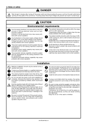
... the rated voltage for the sewing machine's total air consumption. Install the belt covers to its original position. Furthermore, do not drink the oil or eat the grease under any electrical work table which are present can result. Keep the oil out of the reach of receiving a serious electric shock, and problems with correct operation. The power supply capacity should be carried...
... the rated voltage for the sewing machine's total air consumption. Install the belt covers to its original position. Furthermore, do not drink the oil or eat the grease under any electrical work table which are present can result. Keep the oil out of the reach of receiving a serious electric shock, and problems with correct operation. The power supply capacity should be carried...
Instruction Manual - English
Page 4
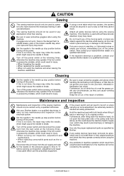
... may result. Any problems in personal injury or damage to the needle up step position before using the sewing machine. Then contact your nearest Brother dealer or a qualified technician. Cleaning Set the needle to the machine. Be sure to the needle up stop position before carrying out inspection, adjustment and repair of the sewing machine should be used without these devices attached, injury may operate if the foot switch is pressed...
... may result. Any problems in personal injury or damage to the needle up step position before using the sewing machine. Then contact your nearest Brother dealer or a qualified technician. Cleaning Set the needle to the machine. Be sure to the needle up stop position before carrying out inspection, adjustment and repair of the sewing machine should be used without these devices attached, injury may operate if the foot switch is pressed...
Instruction Manual - English
Page 5
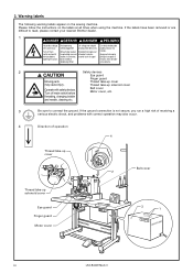
... öffnen. threading, changing bobbin and needle, cleaning etc. 3 Be sure to read, please contact your nearest Brother dealer. 1 Hazardous voltage will cause injury. Warning labels The following warning labels appear on the labels at all times when using the machine. Please follow the instructions on the sewing machine. provoque des blessures. Thread take-up solenoid cover Operate with correct operation may also occur. 4 Direction of receiving...
... öffnen. threading, changing bobbin and needle, cleaning etc. 3 Be sure to read, please contact your nearest Brother dealer. 1 Hazardous voltage will cause injury. Warning labels The following warning labels appear on the labels at all times when using the machine. Please follow the instructions on the sewing machine. provoque des blessures. Thread take-up solenoid cover Operate with correct operation may also occur. 4 Direction of receiving...

Instruction Manual - English
Page 6
... THE SEWING PATTERN ....... 25 7. Adjusting the movable knife 37 10-8. Setting solenoid work clamp mode ..... 59 15.TABLE OF ERROR CODES 60 16.GAUGE PARTS LIST ACCORDING TO SUBCLASSES 62 17.TROUBLESHOOTING 65 18.OPTIONAL PARTS 68 LK3-B434E Mark II Setting reverse work clamp mode ... 57 14-2. Installing the operation panel 9 3-12. Using the bobbin thread counter ....... 47 11-2. DIP switches inside the control box 49 12-3. SPECIFICATIONS 02 2-1. Installing the cushions 7 3-8. Connecting the cords 10 3-14. Cleaning...
... THE SEWING PATTERN ....... 25 7. Adjusting the movable knife 37 10-8. Setting solenoid work clamp mode ..... 59 15.TABLE OF ERROR CODES 60 16.GAUGE PARTS LIST ACCORDING TO SUBCLASSES 62 17.TROUBLESHOOTING 65 18.OPTIONAL PARTS 68 LK3-B434E Mark II Setting reverse work clamp mode ... 57 14-2. Installing the operation panel 9 3-12. Using the bobbin thread counter ....... 47 11-2. DIP switches inside the control box 49 12-3. SPECIFICATIONS 02 2-1. Installing the cushions 7 3-8. Connecting the cords 10 3-14. Cleaning...

Instruction Manual - English
Page 7
... OF EACH PART 1. 1. NAME OF EACH PART !7 u y !3 !2 t !6 o !4 !0 i !5 r [LK3-B434E Mark II/Solenoid specifications] e Specifications with inner clamping device q w !7 u !1 y !3 o !4 !0 i !5 e q Power switch w Control box e Operation panel r Foot switch t Motor y Tension release lever u EMERGENCY STOP switch i Pulley o Spool stand !0 Thread take-up lever !1 Wiper solenoid cover !2 t !6 q w r [LK3-B434E Mark II/Pneumatic specifications] Safety devices; !2 Finger guard !3 Eye guard !4 Thread take-up cover !5 Belt cover !6 Motor cover !7 Thread take-up solenoid cover 1 LK3-B434E Mark II...
... OF EACH PART 1. 1. NAME OF EACH PART !7 u y !3 !2 t !6 o !4 !0 i !5 r [LK3-B434E Mark II/Solenoid specifications] e Specifications with inner clamping device q w !7 u !1 y !3 o !4 !0 i !5 e q Power switch w Control box e Operation panel r Foot switch t Motor y Tension release lever u EMERGENCY STOP switch i Pulley o Spool stand !0 Thread take-up lever !1 Wiper solenoid cover !2 t !6 q w r [LK3-B434E Mark II/Pneumatic specifications] Safety devices; !2 Finger guard !3 Eye guard !4 Thread take-up cover !5 Belt cover !6 Motor cover !7 Thread take-up solenoid cover 1 LK3-B434E Mark II...
Instruction Manual - English
Page 8
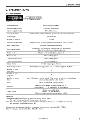
... pneumatic). LK3-B434E Mark II 2 SPECIFICATIONS 2-1. Specifications BROTHER INDUSTRIES, LTD. R-θ intermittent feed mechanism (pulse-motor driven mechanism) 0.1 - 10.0 mm Variable 20,000 stitches (including 10,000 stitches which can be added is within 10,000. 2. For attaching items, sewing labels, etc. SPECIFICATIONS 2. Total number of stitches of stitches Maximum stitch number Work clamp lifter Work clamp height Rotary hook Wiper device Thread trimmer device Thread take-up to sew a pattern, you want to a maximum size of 100...
... pneumatic). LK3-B434E Mark II 2 SPECIFICATIONS 2-1. Specifications BROTHER INDUSTRIES, LTD. R-θ intermittent feed mechanism (pulse-motor driven mechanism) 0.1 - 10.0 mm Variable 20,000 stitches (including 10,000 stitches which can be added is within 10,000. 2. For attaching items, sewing labels, etc. SPECIFICATIONS 2. Total number of stitches of stitches Maximum stitch number Work clamp lifter Work clamp height Rotary hook Wiper device Thread trimmer device Thread take-up to sew a pattern, you want to a maximum size of 100...

Instruction Manual - English
Page 16
... open the control box cover (main P.C. NOTE: When opening . 6. of pins X, Y, Sewing sensor 12-pin Synchronizer 5-pin Machine specification select connector Thread wiper solenoid* Thread take-up solenoid Presser solenoid Thread trimmer solenoid 8-pin 5-pin 4-pin Pulse motor, Y 4-pin (blue) Pulse motor, X 4-pin Operation panel 26-pin Upper shaft motor 3-pin EMERGENCY STOP switch 6-pin Solenoid valve (for pneumatic) and P18 as shown in the work table. 3. LK3-B434E Mark II 10 Securely connect connectors P1 to its original position. 4. Connecting the cords...
... open the control box cover (main P.C. NOTE: When opening . 6. of pins X, Y, Sewing sensor 12-pin Synchronizer 5-pin Machine specification select connector Thread wiper solenoid* Thread take-up solenoid Presser solenoid Thread trimmer solenoid 8-pin 5-pin 4-pin Pulse motor, Y 4-pin (blue) Pulse motor, X 4-pin Operation panel 26-pin Upper shaft motor 3-pin EMERGENCY STOP switch 6-pin Solenoid valve (for pneumatic) and P18 as shown in the work table. 3. LK3-B434E Mark II 10 Securely connect connectors P1 to its original position. 4. Connecting the cords...

Instruction Manual - English
Page 21
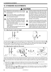
... the machine head, loosen the screws w and r, remove the screw y and then remove the belt cover t first. 3. B. 1. Remove the screw !4 and rubber plug !.5 * Note that the spring !6 will come out when the screw !4 is used , for example, if it is just hooked loosely onto the work table leg when the foot switch is used in Figure. NOTE: If using the two-pedal foot switch as an option for solenoid specifications, change the setting of...
... the machine head, loosen the screws w and r, remove the screw y and then remove the belt cover t first. 3. B. 1. Remove the screw !4 and rubber plug !.5 * Note that the spring !6 will come out when the screw !4 is used , for example, if it is just hooked loosely onto the work table leg when the foot switch is used in Figure. NOTE: If using the two-pedal foot switch as an option for solenoid specifications, change the setting of...
Instruction Manual - English
Page 28
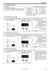
.... !2 3 Depress the foot switch to make sure that the needle hole does not go out of the area circumscribed by the work clamp, before depressing the start switch. * The display will stop flashing and illuminates steadily, and the feed mechanism will move to the sewing start position. 1st step 2nd step This completes the setting of the program number. 5-2-2. Setting the program number 1 Press the...
.... !2 3 Depress the foot switch to make sure that the needle hole does not go out of the area circumscribed by the work clamp, before depressing the start switch. * The display will stop flashing and illuminates steadily, and the feed mechanism will move to the sewing start position. 1st step 2nd step This completes the setting of the program number. 5-2-2. Setting the program number 1 Press the...

Instruction Manual - English
Page 30
... so that the display panel flashes. LK3-B434E Mark II 24 Press the BOBBIN. 5. If the work clamp moves back too far, press the TEST switch r to move backward one stitch at a time while this switch is being pressed. OPERATION 5-4. w RESET e BOBBIN.WIND r TEST Continuing sewing from the point where the thread ended. 1. Press the RESET switch w on the control panel. * The electronic alarm will...
... so that the display panel flashes. LK3-B434E Mark II 24 Press the BOBBIN. 5. If the work clamp moves back too far, press the TEST switch r to move backward one stitch at a time while this switch is being pressed. OPERATION 5-4. w RESET e BOBBIN.WIND r TEST Continuing sewing from the point where the thread ended. 1. Press the RESET switch w on the control panel. * The electronic alarm will...

Instruction Manual - English
Page 33
... the shaft. 2. WIND switch w, de- Keep de- WIND switch w after a set screw t and pull the bobbin presser q outward. Remove the bobbin, hook the thread onto the knife r, and then pull the bobbin in the direction of the arrow to adjust. * If the thread winds on as shown in the direction of the bobbin capacity) has been wound on the operation panel will automatically return to its original position after the machine starts BOBBIN.WIND operating.
... the shaft. 2. WIND switch w, de- Keep de- WIND switch w after a set screw t and pull the bobbin presser q outward. Remove the bobbin, hook the thread onto the knife r, and then pull the bobbin in the direction of the arrow to adjust. * If the thread winds on as shown in the direction of the bobbin capacity) has been wound on the operation panel will automatically return to its original position after the machine starts BOBBIN.WIND operating.

Instruction Manual - English
Page 34
7-5. Replacing the bobbin case and threading the thread 7. case, and then pass the thread thread hole r, and then pull out ap- through the lever you to be changed depending on the article being sewn. Sewing conditions and thread tension Use Upper thread Lower thread Upper thread tension (N) Lower thread tension (N) Thread take-up spring height (mm) Thread take-up spring tension (N) Pre-tension (N) Needle Medium materials Standard hook #50 or equivalent #60 or equivalent 0.6 - 0.9 Large hook ← ← 1.0 - 1.3 0.2 - 0.3 ← 6 - 8 ← 0.15 - 0.35 ← ...
7-5. Replacing the bobbin case and threading the thread 7. case, and then pass the thread thread hole r, and then pull out ap- through the lever you to be changed depending on the article being sewn. Sewing conditions and thread tension Use Upper thread Lower thread Upper thread tension (N) Lower thread tension (N) Thread take-up spring height (mm) Thread take-up spring tension (N) Pre-tension (N) Needle Medium materials Standard hook #50 or equivalent #60 or equivalent 0.6 - 0.9 Large hook ← ← 1.0 - 1.3 0.2 - 0.3 ← 6 - 8 ← 0.15 - 0.35 ← ...

Instruction Manual - English
Page 37
Before starting sewing ...... • Check that the needle bar is at the following times, otherwise the machine may w come into contact with the needle and break the tip of the needle. 1. The feed mechanism will move automatically to the next starting position and the work clamp e will rise. 31 LK3-B434E Mark II When the foot switch is depressed by mistake, which could result in order to lower the work clamp e will lower. rial...
Before starting sewing ...... • Check that the needle bar is at the following times, otherwise the machine may w come into contact with the needle and break the tip of the needle. 1. The feed mechanism will move automatically to the next starting position and the work clamp e will rise. 31 LK3-B434E Mark II When the foot switch is depressed by mistake, which could result in order to lower the work clamp e will lower. rial...
Instruction Manual - English
Page 41
... set screw e and then move the needle bar up or down to adjust so that the tip of the rotary hook is aligned with the needle center line. * When returning the felt support e, place it to its lowest position until they operate correctly before using a DP × 5 needle, use the second reference line from its original position. 35 LK3-B434E Mark II STANDARD ADJUSTMENTS 10. Loosen the screw...
... set screw e and then move the needle bar up or down to adjust so that the tip of the rotary hook is aligned with the needle center line. * When returning the felt support e, place it to its lowest position until they operate correctly before using a DP × 5 needle, use the second reference line from its original position. 35 LK3-B434E Mark II STANDARD ADJUSTMENTS 10. Loosen the screw...

Instruction Manual - English
Page 58
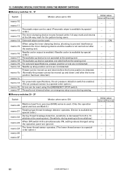
... BOB- When the BOBBIN. Needle stops in the sewing speed.) -- -- memo-0F After sewing is finished, the work clamp automatically opens and closes once (practice operation). -- -- *1 ON for solenoid/heavy material specifications, and "--" for X and Y become the same. -- -- 13. NOTE: After changing the memory switch settings, press the power switch to the next starting point after sewing starts.) Initial value Solenoid Pneumatic -- -- POWER RESET P PROGRAM NO. BOBBIN.WIND SELECT 5. t * The display...
... BOB- When the BOBBIN. Needle stops in the sewing speed.) -- -- memo-0F After sewing is finished, the work clamp automatically opens and closes once (practice operation). -- -- *1 ON for solenoid/heavy material specifications, and "--" for X and Y become the same. -- -- 13. NOTE: After changing the memory switch settings, press the power switch to the next starting point after sewing starts.) Initial value Solenoid Pneumatic -- -- POWER RESET P PROGRAM NO. BOBBIN.WIND SELECT 5. t * The display...
Instruction Manual - English
Page 59
... LK3-B434E Mark II memo-14 Solenoid wiper can be moved up and down until after the sewing end. Needle up device is a specialorder option.) - For pneumatic specifications, the air pressure detection switch is enabled. (The air pressure sensor is not trimmed when an emergency stop position errors are not detected. Thread is a special-order option.) Errors can be reset using the operation panel...
... LK3-B434E Mark II memo-14 Solenoid wiper can be moved up and down until after the sewing end. Needle up device is a specialorder option.) - For pneumatic specifications, the air pressure detection switch is enabled. (The air pressure sensor is not trimmed when an emergency stop position errors are not detected. Thread is a special-order option.) Errors can be reset using the operation panel...

Instruction Manual - English
Page 66
.... memory settings".) Length of thread. Abnormality in the display window. Invalid program number specified. Presser cannot be raised. Installing the V-belt".) Refer to "3-15. Clearing all memory settings. (Refer to eliminate the cause of the control box. Needle bar does not stop position. (Refer to enlargement ratio setting. Cooling fan does not operate. WIND switch to reset the error. Presser is raised. Turn off the power and check...
.... memory settings".) Length of thread. Abnormality in the display window. Invalid program number specified. Presser cannot be raised. Installing the V-belt".) Refer to "3-15. Clearing all memory settings. (Refer to eliminate the cause of the control box. Needle bar does not stop position. (Refer to enlargement ratio setting. Cooling fan does not operate. WIND switch to reset the error. Presser is raised. Turn off the power and check...
Instruction Manual - English
Page 71
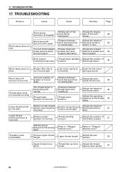
... 65 LK3-B434E Mark II TROUBLESHOOTING Problem Cause Check Remedy Page Work clamp does not rise. Link return spring is incorrect. Bobbin presser position is unhooked. Clearance beween thread wiper and needle tip Thread wiper position Adjust the height of the thread wiper. 42 Adjust the operating distance of the bobbin presser. 27 Stitches being skipped at the sewing start. Thread winding amount Adjust the position of the thread 42 wiper. Grease the presser plate and presser arm 40 lever support. Bobbin winder thread tension stud height Adjust the...
... 65 LK3-B434E Mark II TROUBLESHOOTING Problem Cause Check Remedy Page Work clamp does not rise. Link return spring is incorrect. Bobbin presser position is unhooked. Clearance beween thread wiper and needle tip Thread wiper position Adjust the height of the thread wiper. 42 Adjust the operating distance of the bobbin presser. 27 Stitches being skipped at the sewing start. Thread winding amount Adjust the position of the thread 42 wiper. Grease the presser plate and presser arm 40 lever support. Bobbin winder thread tension stud height Adjust the...

Instruction Manual - English
Page 72
... or burred rotary hook, needle hole plate or needle. Use a thread cooling device (optional). 68 Lower thread tension is too thick for the needle. Bent needle Needle direction Replace the needle. Needle clearance Needle bar lift amount. Needle direction Thread is too strong. Skipped stitches occur. Driver is contacting needle more than is bent. Needle is necessary. TROUBLESHOOTING Remedy Page Upper thread breaks. Upper thread tension Needle is 26 facing forward. Thread melting (synthetic thread) Thread and needle Thread take-up spring tension and height...
... or burred rotary hook, needle hole plate or needle. Use a thread cooling device (optional). 68 Lower thread tension is too thick for the needle. Bent needle Needle direction Replace the needle. Needle clearance Needle bar lift amount. Needle direction Thread is too strong. Skipped stitches occur. Driver is contacting needle more than is bent. Needle is necessary. TROUBLESHOOTING Remedy Page Upper thread breaks. Upper thread tension Needle is 26 facing forward. Thread melting (synthetic thread) Thread and needle Thread take-up spring tension and height...

Instruction Manual - English
Page 73
... stitches occur". Upper thread tension is too weak. Incorrect needle and rotary hook timing. Upper thread tension Adjust the upper thread tension. 29 Lower thread tension is too weak. 17. Work clamp pressure Adjust the work clamp pressure so that the inner 46 clamping device operates. 67 LK3-B434E Mark II The movable knife does not pick up lever stroke. 37 Incorrect thread tightness. Adjust the needle bar lift amount. 35 Refer to adjust the 29 tension. Thread take-up spring tension and height Needle bar lift amount Shuttle race thread guide position...
... stitches occur". Upper thread tension is too weak. Incorrect needle and rotary hook timing. Upper thread tension Adjust the upper thread tension. 29 Lower thread tension is too weak. 17. Work clamp pressure Adjust the work clamp pressure so that the inner 46 clamping device operates. 67 LK3-B434E Mark II The movable knife does not pick up lever stroke. 37 Incorrect thread tightness. Adjust the needle bar lift amount. 35 Refer to adjust the 29 tension. Thread take-up spring tension and height Needle bar lift amount Shuttle race thread guide position...


