
Parts Manual - English
Page 2
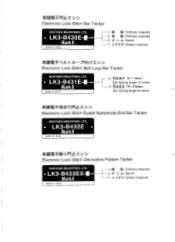
... 2 : r-9.11=€ 6-14mm / Bar tacking length 6-14mm 3 : 115 .thR 14-25mm / Bar tacking length14-25mm 2iKiariPMH7VILLES-Electronic Lock Stitch Eyelet Buttonhole End Bar Tacker BROTHER INDUSTRIES, LTD. • LK3-B432E • Markil MADE IN JAPAN islIMPO sz. *trITAPPIIEZ >2 Electronic Lock Stitch Bar Tacker BROTHER INDUSTRIES, LTD. • LK3-B430E- - Markll MADE IN JAPAN 1 : t OR / Ordinary materials 2 = A / Denim 7 :)( IJ -PX/ Knitted materials Electronic Lock Stitch Decorative Pattern Tacker BROTHER INDUSTRIES, LTD. • LK3-B433EX- -
... 2 : r-9.11=€ 6-14mm / Bar tacking length 6-14mm 3 : 115 .thR 14-25mm / Bar tacking length14-25mm 2iKiariPMH7VILLES-Electronic Lock Stitch Eyelet Buttonhole End Bar Tacker BROTHER INDUSTRIES, LTD. • LK3-B432E • Markil MADE IN JAPAN islIMPO sz. *trITAPPIIEZ >2 Electronic Lock Stitch Bar Tacker BROTHER INDUSTRIES, LTD. • LK3-B430E- - Markll MADE IN JAPAN 1 : t OR / Ordinary materials 2 = A / Denim 7 :)( IJ -PX/ Knitted materials Electronic Lock Stitch Decorative Pattern Tacker BROTHER INDUSTRIES, LTD. • LK3-B433EX- -

Parts Manual - English
Page 4
... in design without prior notice. 3. Feed mechanism (B431E MarkII) 11 C4. Bobbin winder mechanism 29 J . Thread take-up mechanism 35 M. Power supply equipment mechanism 49 S. Power table 53 U1 . Lubrication 25 G. Thread trimmer mechanism 31 K. Printed circuit board mechanism 39 Q1 . Control box mechanism 41 Q2. Upper shaft and needle bar mechanism 3 Cl . Warning labels 82 Index 83 Threading mechanism 27 H. Accessories 65 Z2. Gauge parts List...
... in design without prior notice. 3. Feed mechanism (B431E MarkII) 11 C4. Bobbin winder mechanism 29 J . Thread take-up mechanism 35 M. Power supply equipment mechanism 49 S. Power table 53 U1 . Lubrication 25 G. Thread trimmer mechanism 31 K. Printed circuit board mechanism 39 Q1 . Control box mechanism 41 Q2. Upper shaft and needle bar mechanism 3 Cl . Warning labels 82 Index 83 Threading mechanism 27 H. Accessories 65 Z2. Gauge parts List...
Parts Manual - English
Page 31
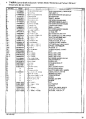
... SHUTTLE RACE BASE THREAD GUIDE, ;S-RACE SCREW, PAN 5M3.18-40X4 SETTING CLAW, S-RACE BODY SPRING, COMPRESSION WASHER, 3.2 SCREW, PAN SM3.18-40X7 FELT WICK, 3X3 L= 360 WICK, 3X3 L = 300 WICK, 3X3 L = 100 SET SCREW, SOCKET SM5.95 ADJUSTING STUD 0 RING, PW3 RETAINING RING, E7 DRIVER BOLT, SOCKET M5X14 SHUTTLE RACE BODY SHUTTLE HOOK ASSY, W/BOX NEEDLE ROLLER, 4X19.8 BOBBIN CASE ASSY, TENSION SPRING SCREW SPRING, ANTI-SPIN BOBBIN FELT FELT SUPPORT SUPPORT SHOULDER SCREW...
... SHUTTLE RACE BASE THREAD GUIDE, ;S-RACE SCREW, PAN 5M3.18-40X4 SETTING CLAW, S-RACE BODY SPRING, COMPRESSION WASHER, 3.2 SCREW, PAN SM3.18-40X7 FELT WICK, 3X3 L= 360 WICK, 3X3 L = 300 WICK, 3X3 L = 100 SET SCREW, SOCKET SM5.95 ADJUSTING STUD 0 RING, PW3 RETAINING RING, E7 DRIVER BOLT, SOCKET M5X14 SHUTTLE RACE BODY SHUTTLE HOOK ASSY, W/BOX NEEDLE ROLLER, 4X19.8 BOBBIN CASE ASSY, TENSION SPRING SCREW SPRING, ANTI-SPIN BOBBIN FELT FELT SUPPORT SUPPORT SHOULDER SCREW...
Instruction Manual - English
Page 3
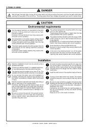
.... ii LK3-B430E-, B431E-, B432E-, B433E- Insufficient power supply capacity may operate if the foot switch is not secure, you run a high risk of the control box. Hold the machine head with correct operation. Notes on safety DANGER Wait at least 25 mm away from the wall outlet. All cords should be secured in injury. Install the belt covers to connect...
.... ii LK3-B430E-, B431E-, B432E-, B433E- Insufficient power supply capacity may operate if the foot switch is not secure, you run a high risk of the control box. Hold the machine head with correct operation. Notes on safety DANGER Wait at least 25 mm away from the wall outlet. All cords should be secured in injury. Install the belt covers to connect...

Instruction Manual - English
Page 4
... the machine. Attach all safety precautions. Cleaning Set the needle to the needle up step position before using a work table which could result in safe use beforehand. LK3-B430E-, B431E-, B432E-, B433E- The sewing machine should not be secured in such a way so that if a needle breaks, parts of the broken needle may strike the needle, which might cause the needle to break. Turn off the power switch at the following times, otherwise the machine...
... the machine. Attach all safety precautions. Cleaning Set the needle to the needle up step position before using a work table which could result in safe use beforehand. LK3-B430E-, B431E-, B432E-, B433E- The sewing machine should not be secured in such a way so that if a needle breaks, parts of the broken needle may strike the needle, which might cause the needle to break. Turn off the power switch at the following times, otherwise the machine...
Instruction Manual - English
Page 5
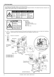
... abrir esta cubierta. 2 Safety devices Eye guard Finger guard Moving parts Thread take -up solenoid cover Operate with correct operation may cause injury. Hochspannung Un voltage non adapté verletzungsgefahr! Turn off main switch before opening this cover. 3. Warning labels The following warning labels appear on the labels at all times when using the machine. Please follow the instructions on the sewing machine.
... abrir esta cubierta. 2 Safety devices Eye guard Finger guard Moving parts Thread take -up solenoid cover Operate with correct operation may cause injury. Hochspannung Un voltage non adapté verletzungsgefahr! Turn off main switch before opening this cover. 3. Warning labels The following warning labels appear on the labels at all times when using the machine. Please follow the instructions on the sewing machine.
Instruction Manual - English
Page 6
... the upper thread 23 7-4. Cleaning the rotary hook 29 9-2. NAME OF EACH PART 01 2. Installing the machine head 12 3-9. Installing the belt cover 16 3-16. CORRECT USE 23 7-1. Sewing conditions and thread tension 25 8. Adjusting the needle bar lift amount 32 10-3. SEWING 28 9. CHECKING THE SEWING PATTERN ....... 22 7. Installing the motor pulley 9 3-4. Operating procedure 21 6. CONTENTS 1. INSTALLATION 07 3-1. Winding the lower thread 24 7-5. Name and function of each operation panel item 19 5-2. Cleaning the control box...
... the upper thread 23 7-4. Cleaning the rotary hook 29 9-2. NAME OF EACH PART 01 2. Installing the machine head 12 3-9. Installing the belt cover 16 3-16. CORRECT USE 23 7-1. Sewing conditions and thread tension 25 8. Adjusting the needle bar lift amount 32 10-3. SEWING 28 9. CHECKING THE SEWING PATTERN ....... 22 7. Installing the motor pulley 9 3-4. Operating procedure 21 6. CONTENTS 1. INSTALLATION 07 3-1. Winding the lower thread 24 7-5. Name and function of each operation panel item 19 5-2. Cleaning the control box...
Instruction Manual - English
Page 8
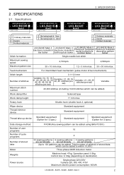
... Electronic lockstitch belt loop bar tacker LK3-B432E Mark II Electronic lockstitch eyelet buttonhole end bar tacker LK3-B433E Mark II Electronic lockstitch decorative pattern tacker Single needle lock stitch Maximum sewing speed Maximum pattern size 2,700rpm 30 × 10 mm max. 12 × 3 mm max. 2,500rpm 30 × 30 mm max. Feed mechanism R-θ intermittent feed mechanism (pulse-motor driven mechanism) Stitch length Number of stitches Maximum stitch number 0.1-10.0 mm Variable...
... Electronic lockstitch belt loop bar tacker LK3-B432E Mark II Electronic lockstitch eyelet buttonhole end bar tacker LK3-B433E Mark II Electronic lockstitch decorative pattern tacker Single needle lock stitch Maximum sewing speed Maximum pattern size 2,700rpm 30 × 10 mm max. 12 × 3 mm max. 2,500rpm 30 × 30 mm max. Feed mechanism R-θ intermittent feed mechanism (pulse-motor driven mechanism) Stitch length Number of stitches Maximum stitch number 0.1-10.0 mm Variable...

Instruction Manual - English
Page 22
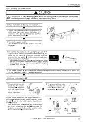
... come out when the screw !4 is just hooked loosely onto the work table leg when the foot switch is used, for example, if it may cause the sewing machine to front, and then install it with the two screws w, the two screws r and the screw y. * When tilting back the machine head, loosen the screws w and r, remove the screw y and then remove the belt cover t first. 3. Turn foot switch support plate B !3 back to operate incorrectly. B. Insert...
... come out when the screw !4 is just hooked loosely onto the work table leg when the foot switch is used, for example, if it may cause the sewing machine to front, and then install it with the two screws w, the two screws r and the screw y. * When tilting back the machine head, loosen the screws w and r, remove the screw y and then remove the belt cover t first. 3. Turn foot switch support plate B !3 back to operate incorrectly. B. Insert...

Instruction Manual - English
Page 29
... power switch before installing the needle, otherwise the machine may operate if the foot switch is on which needle and thread to open the tension disc w and pull the thread through. [Two holes] Spun rayon yarn [One hole] 9 q 11 10 Synthetic thread 9 10 11 w [When using the liquid cooling tank] 9 11 10 Approx. 40mm 23 LK3-B430E-, B431E-, B432E-, B433E- Threading the upper thread CAUTION Turn off the power switch before threading...
... power switch before installing the needle, otherwise the machine may operate if the foot switch is on which needle and thread to open the tension disc w and pull the thread through. [Two holes] Spun rayon yarn [One hole] 9 q 11 10 Synthetic thread 9 10 11 w [When using the liquid cooling tank] 9 11 10 Approx. 40mm 23 LK3-B430E-, B431E-, B432E-, B433E- Threading the upper thread CAUTION Turn off the power switch before threading...
Instruction Manual - English
Page 30
... a set screw t and pull the bobbin presser q outward. If you release the foot switch before winding is not touching the presser foot, and then while pressing the BOBBIN. Release the BOBBIN. eral times in B,turn the bobbin winder thead tension stud w counterclockwise. 8. Thread the thread as shown in the direction of the bobbin capacity ) has been wound on the operation panel will automatically return to its original position after the machine starts BOBBIN.WIND operating. if...
... a set screw t and pull the bobbin presser q outward. If you release the foot switch before winding is not touching the presser foot, and then while pressing the BOBBIN. Release the BOBBIN. eral times in B,turn the bobbin winder thead tension stud w counterclockwise. 8. Thread the thread as shown in the direction of the bobbin capacity ) has been wound on the operation panel will automatically return to its original position after the machine starts BOBBIN.WIND operating. if...
Instruction Manual - English
Page 31
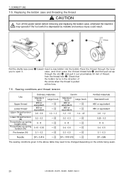
... the shuttle race cover q toward Insert a new bobbin into the bobbin Pass the thread through the slot w and pull it . from the thread hole e. Check that the bobbin turns in the above table may operate if the foot switch is pulled at this time. 7-6 . Sewing conditions and thread tension Use Upper thread Lower thread Upper thread tension (N) Lower thread tension (N) Thread take-up spring height (mm) Thread take-up spring tension (N) Ordinary materials Standard hook #50 or equivalent #60 or equivalent Large hook ˡ ˡ...
... the shuttle race cover q toward Insert a new bobbin into the bobbin Pass the thread through the slot w and pull it . from the thread hole e. Check that the bobbin turns in the above table may operate if the foot switch is pulled at this time. 7-6 . Sewing conditions and thread tension Use Upper thread Lower thread Upper thread tension (N) Lower thread tension (N) Thread take-up spring height (mm) Thread take-up spring tension (N) Ordinary materials Standard hook #50 or equivalent #60 or equivalent Large hook ˡ ˡ...
Instruction Manual - English
Page 34
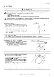
... POWER indicator will illuminate and the program number will start operating. 1st Step 2nd Step q 3. SEWING 8. Do not touch any of the needle. 1. Before starting position and the work clamp q will lower. The feed mechanism will move to the 2nd step while the display is depressed by mistake, which could result in the display.) 2. The work clamp q, and then depress the foot switch. LK3-B430E-, B431E-, B432E...
... POWER indicator will illuminate and the program number will start operating. 1st Step 2nd Step q 3. SEWING 8. Do not touch any of the needle. 1. Before starting position and the work clamp q will lower. The feed mechanism will move to the 2nd step while the display is depressed by mistake, which could result in the display.) 2. The work clamp q, and then depress the foot switch. LK3-B430E-, B431E-, B432E...
Instruction Manual - English
Page 47
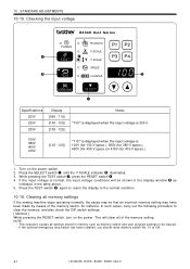
P1 P2 X-SCALE r w P3 P4 RESET Y-SCALE SPEED e TEST COUNTER t BOBBIN.WIND SELECT q Specifications 200V 220V 230V Display [090 - 110] [100 - 120] [105 - 125] Notes "100" is displayed when the input voltage is 200 V. 100V 380V... to ON. 41 LK3-B430E-, B431E-, B432E-, B433E- Checking the input voltage B430E ɹɹɹSeries POWER P PROGRAM NO. NOTE • This operation causes all memory settings If the sewing machine stops operating normally, the cause may have been made by means of the memory setting. Clearing all settings stored in the table above. 5. Press...
P1 P2 X-SCALE r w P3 P4 RESET Y-SCALE SPEED e TEST COUNTER t BOBBIN.WIND SELECT q Specifications 200V 220V 230V Display [090 - 110] [100 - 120] [105 - 125] Notes "100" is displayed when the input voltage is 200 V. 100V 380V... to ON. 41 LK3-B430E-, B431E-, B432E-, B433E- Checking the input voltage B430E ɹɹɹSeries POWER P PROGRAM NO. NOTE • This operation causes all memory settings If the sewing machine stops operating normally, the cause may have been made by means of the memory setting. Clearing all settings stored in the table above. 5. Press...
Instruction Manual - English
Page 54
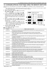
... When sewing using the optional spring for extra-heavy material) Enlargement and reduction ratio settings for enlargements and reductions is finished, the work clamp automatically opens and closes once (practice operation). *B432E Mark II only. B430E ɹɹɹSeries 3. RESET P PROGRAM NO. When the BOBBIN. memo-01 Work clamp will move automatically to normal. Work clamp closes when it moves to the starting point at the minimum speed...
... When sewing using the optional spring for extra-heavy material) Enlargement and reduction ratio settings for enlargements and reductions is finished, the work clamp automatically opens and closes once (practice operation). *B432E Mark II only. B430E ɹɹɹSeries 3. RESET P PROGRAM NO. When the BOBBIN. memo-01 Work clamp will move automatically to normal. Work clamp closes when it moves to the starting point at the minimum speed...

Instruction Manual - English
Page 58
... the problem. Check that all switch A-6. Machine motor operation error. Check the synchronizer connection. E-30 E-31 Data is blocked with the sewing machine, a buzzer will sound and an error code will appear in the sewing data. Press the RESET switch, and then reset the memory switches "30" and "31" or enlargement ratio. memory settings".) E-40 Length of the control box. E-50 Needle bar does not stop position".) Check...
... the problem. Check that all switch A-6. Machine motor operation error. Check the synchronizer connection. E-30 E-31 Data is blocked with the sewing machine, a buzzer will sound and an error code will appear in the sewing data. Press the RESET switch, and then reset the memory switches "30" and "31" or enlargement ratio. memory settings".) E-40 Length of the control box. E-50 Needle bar does not stop position".) Check...
Instruction Manual - English
Page 68
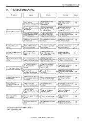
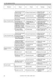
... back. Hook the link return spring properly. Incorrect position of the work clamp to within 17 mm. 36 • 37 Grease the presser plate and presser arm 36 lever support. Threads comes unthreaded. Upper thread length Adjust the subtension. 26 Upper thread is contacting thread wiper. Presser is too short. Bobbin presser position is sluggish. Refer to "Skipped stitches occur" Refer to one side. TROUBLESHOOTING Remedy Page *1 Work clamp operation is incorrect. Clearance beween thread wiper and needle tip Thread wiper position Adjust the...
... back. Hook the link return spring properly. Incorrect position of the work clamp to within 17 mm. 36 • 37 Grease the presser plate and presser arm 36 lever support. Threads comes unthreaded. Upper thread length Adjust the subtension. 26 Upper thread is contacting thread wiper. Presser is too short. Bobbin presser position is sluggish. Refer to "Skipped stitches occur" Refer to one side. TROUBLESHOOTING Remedy Page *1 Work clamp operation is incorrect. Clearance beween thread wiper and needle tip Thread wiper position Adjust the...
Instruction Manual - English
Page 69
... Adjust the upper thread tension. 26 Install the needle so that the groove is 23 facing forward. Needle is necessary. 16. Driver is contacting needle more than is installed incorrectly. Thread take -up spring. Damaged or burred rotary hook, needle hole plate or needle. Needle direction Install the needle so that the groove is 23 facing forward. Use a thread cooling device (optional). 65 Lower thread tension is too thin. Needle is too strong. TROUBLESHOOTING Problem Cause Check Remedy Page Upper thread breaks...
... Adjust the upper thread tension. 26 Install the needle so that the groove is 23 facing forward. Needle is necessary. 16. Driver is contacting needle more than is installed incorrectly. Thread take -up spring. Damaged or burred rotary hook, needle hole plate or needle. Needle direction Install the needle so that the groove is 23 facing forward. Use a thread cooling device (optional). 65 Lower thread tension is too thin. Needle is too strong. TROUBLESHOOTING Problem Cause Check Remedy Page Upper thread breaks...
Instruction Manual - English
Page 70
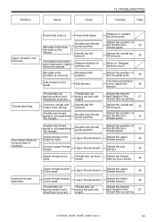
.... Upper thread length Adjust the subtension. 26 Upper thread is incorrect. Thread take -up spring tension and height are incorrect. Mark II 64 TROUBLESHOOTING Remedy Page Upper thread is too weak. Poor seam finish on reverse side of the shuttle race 33 thread guide. Fixed knife blade Movable knife does not pick up lever stroke. 34 Incorrect thread tightness. Thread take -up spring tension and height are incorrect. Incorrect needle and rotary hook timing. Thread take-up spring tension...
.... Upper thread length Adjust the subtension. 26 Upper thread is incorrect. Thread take -up spring tension and height are incorrect. Mark II 64 TROUBLESHOOTING Remedy Page Upper thread is too weak. Poor seam finish on reverse side of the shuttle race 33 thread guide. Fixed knife blade Movable knife does not pick up lever stroke. 34 Incorrect thread tightness. Thread take -up spring tension and height are incorrect. Incorrect needle and rotary hook timing. Thread take-up spring tension...

Hand Book - English
Page 1
.... LK3-B432E MarkII List of stitches Max. of user programs No. LK3-B432EMark II Electronic Lockstitch Eyelet Buttonhole End Bar Tacker Specifications Application Stitch formation Max. stitch number Work clamp lifter Work clamp height Hook Wiper device Thread trimmer device No. Sewing pattern No. of stitches Pattern size X-Y (mm) 01 21 6 ×2 02 28 6 ×2 03 35 6 ×2 2000.7 LK3−B432E Mark II 1/8 Total number of stitches of stored data Motor Weights Power supply Medium materials Single needle lock stitch 2,700...
.... LK3-B432E MarkII List of stitches Max. of user programs No. LK3-B432EMark II Electronic Lockstitch Eyelet Buttonhole End Bar Tacker Specifications Application Stitch formation Max. stitch number Work clamp lifter Work clamp height Hook Wiper device Thread trimmer device No. Sewing pattern No. of stitches Pattern size X-Y (mm) 01 21 6 ×2 02 28 6 ×2 03 35 6 ×2 2000.7 LK3−B432E Mark II 1/8 Total number of stitches of stored data Motor Weights Power supply Medium materials Single needle lock stitch 2,700...


