
Service Manual
Page 2
... M Threading 17 Ej Needle bar 17 M Presser arm 19 M Disc clearances of main and sub tensions 20 to denim stitches 36 • List of, replacement parts 17 THOUS CHA 39 shuttle mechanisms 3 M Clutch mechanism 4 M Power work clamp lifter 31 Thread trimmer 32 • Thread tension and tension release 33 • Thread...
... M Threading 17 Ej Needle bar 17 M Presser arm 19 M Disc clearances of main and sub tensions 20 to denim stitches 36 • List of, replacement parts 17 THOUS CHA 39 shuttle mechanisms 3 M Clutch mechanism 4 M Power work clamp lifter 31 Thread trimmer 32 • Thread tension and tension release 33 • Thread...
Service Manual
Page 5
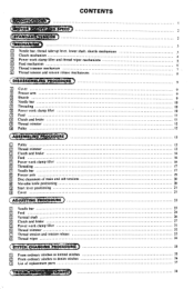
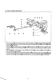
... (1). ® e 6. Rock cear s engages lower shaft gear ® which is guided by needle bar clamp 0. shaft. 5. which is moved up and down via the crank part ® of crank rod ® is gripped by needle bar bushing U 0. The louer end of the upper e. needle bar bushing D 0 and needle bar guide slide...
... (1). ® e 6. Rock cear s engages lower shaft gear ® which is guided by needle bar clamp 0. shaft. 5. which is moved up and down via the crank part ® of crank rod ® is gripped by needle bar bushing U 0. The louer end of the upper e. needle bar bushing D 0 and needle bar guide slide...
Service Manual
Page 6
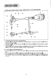
... direction, roller 0 is connected toclutch lever0,and the other end toclutchactuatinglever to the upper shaft. 2. gets in the arrow direction, the low speed part® of steel ball 0 to convey the power to drive clutch cam lever 0 about clutch actuating lever shaft 0 so that roller holderID comes ...under roller O. When roller projected part goes up on the of feed came so high speed part © of clutch cam This makes the machine sew 2 stitches at high speed. 4. speed part 0 of clutch cam control cam lever roller ® falls from the ...
... direction, roller 0 is connected toclutch lever0,and the other end toclutchactuatinglever to the upper shaft. 2. gets in the arrow direction, the low speed part® of steel ball 0 to convey the power to drive clutch cam lever 0 about clutch actuating lever shaft 0 so that roller holderID comes ...under roller O. When roller projected part goes up on the of feed came so high speed part © of clutch cam This makes the machine sew 2 stitches at high speed. 4. speed part 0 of clutch cam control cam lever roller ® falls from the ...
Service Manual
Page 7
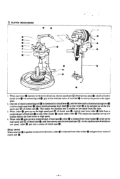
... roller 0 attached to the lower end of clutch actuating lever Q is fitted to work clamp lifter lever that roller 0 disengage: from the cam part @ so that work clamp lifter plate is connected to rod A via actuatinglever shaft 0 as fulcrum. 4. contacts power pulley O. When work clamp ... lowered about work clamp lifter roller shaft ® disengages from start lever claw upon sewing the fiial stitch, roller disengages from the cam part QQ of a turn . 2. Presser arm lever which is pushed up by work clamp ® is connected to connectingleverm toconvey its motion...
... roller 0 attached to the lower end of clutch actuating lever Q is fitted to work clamp lifter lever that roller 0 disengage: from the cam part @ so that work clamp lifter plate is connected to rod A via actuatinglever shaft 0 as fulcrum. 4. contacts power pulley O. When work clamp ... lowered about work clamp lifter roller shaft ® disengages from start lever claw upon sewing the fiial stitch, roller disengages from the cam part QQ of a turn . 2. Presser arm lever which is pushed up by work clamp ® is connected to connectingleverm toconvey its motion...
Service Manual
Page 9
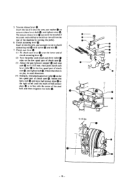
roller 0 in contact with the cam part® of a turn in the arrow direction. When roller rides on the periphery of a turn and movable knife m cuts the thread. -7- roller holders gets under ...
roller 0 in contact with the cam part® of a turn in the arrow direction. When roller rides on the periphery of a turn and movable knife m cuts the thread. -7- roller holders gets under ...
Service Manual
Page 10
... started tension release pin 0 is engaged with roller 0 conveys the motion to tension release bar 0 via guide stud which is located at the cam part O: and when the stop position. and immediately before the stop cam reaches 90° ® ®. The tension release mechanism is at the cam... part 0; When the clutch is engaged 90° before the stop cam reaches the stop position upon sewing the final stitch, tension release lever which ...
... started tension release pin 0 is engaged with roller 0 conveys the motion to tension release bar 0 via guide stud which is located at the cam part O: and when the stop position. and immediately before the stop cam reaches 90° ® ®. The tension release mechanism is at the cam... part 0; When the clutch is engaged 90° before the stop cam reaches the stop position upon sewing the final stitch, tension release lever which ...
Service Manual
Page 17
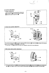
... turning the pulley. 6. loosen two bolts with and move ball presser plate to the left until clutch cam lever roller rides on the low speed part of the steel ball. I ) e 7. The tension release leer® can easily be installed if the crank rod is shifted to 0 the right or left as... tighten bolt m. Clutch actuating lever 0 e Insert it into the arm. and connect its tip to 6 = 0.5 mm. and tighten screw Q. lever roller to the low speed part of it into the arm.
... turning the pulley. 6. loosen two bolts with and move ball presser plate to the left until clutch cam lever roller rides on the low speed part of the steel ball. I ) e 7. The tension release leer® can easily be installed if the crank rod is shifted to 0 the right or left as... tighten bolt m. Clutch actuating lever 0 e Insert it into the arm. and connect its tip to 6 = 0.5 mm. and tighten screw Q. lever roller to the low speed part of it into the arm.
Service Manual
Page 26
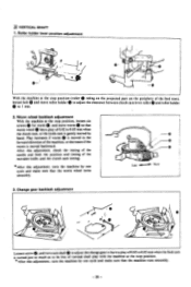
Worm wheel backlash adjustment With the machine at the stop position (roller 0 riding on the projected part on the periphery of 0.02 to 0.05 mm when the clutch cam, or the knife cam is moved backward. Play increases if worm 0 is moved ...
Worm wheel backlash adjustment With the machine at the stop position (roller 0 riding on the projected part on the periphery of 0.02 to 0.05 mm when the clutch cam, or the knife cam is moved backward. Play increases if worm 0 is moved ...
Service Manual
Page 27
... so that the clutch lever spring be removed for easy adjustment. 3. Meet 0 O O 2. With clutch cam lever roller 0 on the low speed part ofclutch cam0, loosen two bolts0 and move ball presser plate 0 to 6 ± 0.5 mm. * In this case. it is suggested that the bottom... clutch lever 0. 0-- 0 - Ball presser plate position adjustment 0 ••• 0 - 0 (I ) With clutch cam lever roller 0 on the low speed part 0 of the steel ball. - 27 - Clutch lever position adjustment 6±0.5ccra • t. 00- loosen bolt 0 and adjust the clearance between stop position. .117...
... so that the clutch lever spring be removed for easy adjustment. 3. Meet 0 O O 2. With clutch cam lever roller 0 on the low speed part ofclutch cam0, loosen two bolts0 and move ball presser plate 0 to 6 ± 0.5 mm. * In this case. it is suggested that the bottom... clutch lever 0. 0-- 0 - Ball presser plate position adjustment 0 ••• 0 - 0 (I ) With clutch cam lever roller 0 on the low speed part 0 of the steel ball. - 27 - Clutch lever position adjustment 6±0.5ccra • t. 00- loosen bolt 0 and adjust the clearance between stop position. .117...
Service Manual
Page 35
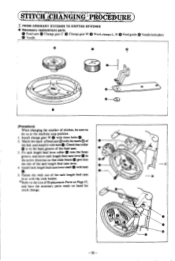
... change . 0 _0 -35- I. be sure to the List of the bed. s 3. and install it with the mark ® of Replacement Parts on Page 37. Match the mark of the tack length feed cam lever. 4. Install tack length feed cam lever shaft with bolt 5. (STITCHtHiNgiNcPPAOCEOURE 0 00... T FROM ORDINARY STITCHES TO KNITTED STITCHES • Necessary replacement parts Feed cam 0 Change gear C Change gear W Work clamps L. Check that roller OtO is in the arrow direction so that slide block gets ...
... change . 0 _0 -35- I. be sure to the List of the bed. s 3. and install it with the mark ® of Replacement Parts on Page 37. Match the mark of the tack length feed cam lever. 4. Install tack length feed cam lever shaft with bolt 5. (STITCHtHiNgiNcPPAOCEOURE 0 00... T FROM ORDINARY STITCHES TO KNITTED STITCHES • Necessary replacement parts Feed cam 0 Change gear C Change gear W Work clamps L. Check that roller OtO is in the arrow direction so that slide block gets ...
Service Manual
Page 36
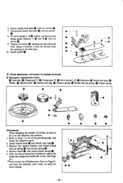
... 40 0 O • 0- --© (Procedure) When changing the number of Replacement Parts on Page 37, and have the necessary parts ready on the preceding page, and install the respective parts. 2. Install shuttle hook 0 and shuttle race ring 0. 3. Remove the tension bracket, and...the List of stitches, be sure to do so at the machine stop position. screws G. 9. FROM ORDINARY STITCHES TO DENIM STITCHS • Necessary replacement parts 49 0 Feed cam 0 Change gear C Change gear W Work clamps L. Temporarily fasten feed plate with two screws (D. 7. and fasten work clamps L....
... 40 0 O • 0- --© (Procedure) When changing the number of Replacement Parts on Page 37, and have the necessary parts ready on the preceding page, and install the respective parts. 2. Install shuttle hook 0 and shuttle race ring 0. 3. Remove the tension bracket, and...the List of stitches, be sure to do so at the machine stop position. screws G. 9. FROM ORDINARY STITCHES TO DENIM STITCHS • Necessary replacement parts 49 0 Feed cam 0 Change gear C Change gear W Work clamps L. Temporarily fasten feed plate with two screws (D. 7. and fasten work clamps L....
Service Manual
Page 37
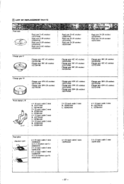
... 3 mm) 153206-0-01 12 x 24 (Sunken type S) 153207-0-01 6 x 23 (tack width 3 mm) 152792-0-01 5 x 13 (tack width 2 mm) 152791-0-01 - 37 - M LIST OF REPLACEMENT PARTS Nam0vab;
... 3 mm) 153206-0-01 12 x 24 (Sunken type S) 153207-0-01 6 x 23 (tack width 3 mm) 152792-0-01 5 x 13 (tack width 2 mm) 152791-0-01 - 37 - M LIST OF REPLACEMENT PARTS Nam0vab;
Service Manual
Page 42
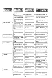
...Adjust needle and teed T timing. Thread retainer position is bent. Haws Thread retainer position Flaws Needle and shuttle hook clearance Polish or replace delectise parts. Needle bar stroke Adjust needle bar stroke. 23 Clearance between needle and shuttle hook point is installed in wrong way. HNeedle and shuttle hook ... bend Adjust driser and needle contact. great. burrs Heat -. Thread take-up spring tension and height. 2 1 A Polish or replace delectise parts. Needle is too n great. • • tv:;71-;-aiTroublei1, - .73 • Upper thread breaks.
...Adjust needle and teed T timing. Thread retainer position is bent. Haws Thread retainer position Flaws Needle and shuttle hook clearance Polish or replace delectise parts. Needle bar stroke Adjust needle bar stroke. 23 Clearance between needle and shuttle hook point is installed in wrong way. HNeedle and shuttle hook ... bend Adjust driser and needle contact. great. burrs Heat -. Thread take-up spring tension and height. 2 1 A Polish or replace delectise parts. Needle is too n great. • • tv:;71-;-aiTroublei1, - .73 • Upper thread breaks.

