
Service Manual
Page 2
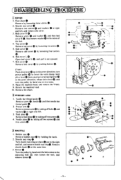
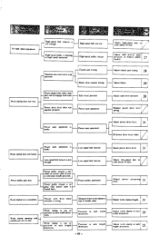
..., - , D SPEED 2 NtiolIECI IIS 3 Needle bar, thread take-up lever, lower shaft. M Cover 9 • Presser arm 9 M Shuttle 9 E Needle bar 10 Threading 10 M Power work clamp lifter 10 Feed II M Clutch and brake 11 M Thread trimmer 12 g Pulley 12 13 • Pulley 13 E Thread trimmer 13 I Clutch and brake 14 J Feed 16 M Power work clamp lifter 16 M Threading 17 Ej Needle bar 17 M Presser arm 19 M Disc clearances of main and sub tensions 20 to Movable knife positioning 20 M Start lever positioning 21 El Cover 21 ADJUSTING...
..., - , D SPEED 2 NtiolIECI IIS 3 Needle bar, thread take-up lever, lower shaft. M Cover 9 • Presser arm 9 M Shuttle 9 E Needle bar 10 Threading 10 M Power work clamp lifter 10 Feed II M Clutch and brake 11 M Thread trimmer 12 g Pulley 12 13 • Pulley 13 E Thread trimmer 13 I Clutch and brake 14 J Feed 16 M Power work clamp lifter 16 M Threading 17 Ej Needle bar 17 M Presser arm 19 M Disc clearances of main and sub tensions 20 to Movable knife positioning 20 M Start lever positioning 21 El Cover 21 ADJUSTING...
Service Manual
Page 3
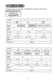
... . 1 i t t I .{ I 1 . - , , _rJ; ..„..,.--t----- t t 't 42 35 28 Tack length 7 - 16 Tack width 1 - 2 (3) Needle DP x 5 #16 Presser foot stroke Sewing speed 1 7 - 20 1- 3 DPx 17 #19 17 mm 2.000 rpm 6.5 - 16 4 - 10 1- 2 (3) DP x 5 #16 Sub-class Main uses Decorative Stitching Number of stitches -1 -2 Ordinary clothes 1 i i i . , i I, i i i. i k t 4. : t t it i t 4 i . O1 ' ! The table below shows the sub-classes of the LK3-6430 type high speed bar tacking machine. t t't t t i 'I i i 1 -3 Denim ' /!'i iiiil .tiii IU -4 -5 Ordinary clothes...
... . 1 i t t I .{ I 1 . - , , _rJ; ..„..,.--t----- t t 't 42 35 28 Tack length 7 - 16 Tack width 1 - 2 (3) Needle DP x 5 #16 Presser foot stroke Sewing speed 1 7 - 20 1- 3 DPx 17 #19 17 mm 2.000 rpm 6.5 - 16 4 - 10 1- 2 (3) DP x 5 #16 Sub-class Main uses Decorative Stitching Number of stitches -1 -2 Ordinary clothes 1 i i i . , i I, i i i. i k t 4. : t t it i t 4 i . O1 ' ! The table below shows the sub-classes of the LK3-6430 type high speed bar tacking machine. t t't t t i 'I i i 1 -3 Denim ' /!'i iiiil .tiii IU -4 -5 Ordinary clothes...
Service Manual
Page 6
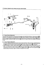
... cam control cam lever roller ® falls from roller holder 0 and gets into a recess of clutch cam This makes the machine sew 2 stitches at high speed. 4. which is released from the start lever 0 operates in line with the center of ball presser plate 0. When roller goes up on the low ®. the low speed part ®. This makes the machine sew up on the of feed came so high speed part...
... cam control cam lever roller ® falls from roller holder 0 and gets into a recess of clutch cam This makes the machine sew 2 stitches at high speed. 4. which is released from the start lever 0 operates in line with the center of ball presser plate 0. When roller goes up on the low ®. the low speed part ®. This makes the machine sew up on the of feed came so high speed part...
Service Manual
Page 10
... feeding the necessary length of work clamp lifter mechanism. tension release pin 0 rides on the cam part O to release tension discs II) and simultaneously conveys the motion to thread take-up lever via tension release lever shaft 0 as fulcrum. 2. When the machine is started , tension release pin 0 is at the cam part 0; Tension release bar 0 is connected to tension release bar 0 via guide stud which is engaged with roller 0 conveys the motion to the upper...
... feeding the necessary length of work clamp lifter mechanism. tension release pin 0 rides on the cam part O to release tension discs II) and simultaneously conveys the motion to thread take-up lever via tension release lever shaft 0 as fulcrum. 2. When the machine is started , tension release pin 0 is at the cam part 0; Tension release bar 0 is connected to tension release bar 0 via guide stud which is engaged with roller 0 conveys the motion to the upper...
Service Manual
Page 11
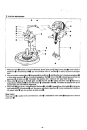
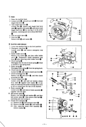
... to lower the work clamp. and then needle bar thread guide 2. G. 4. and remove the cover. 3. turn the pulley by pushing button Q. (Note) Push drive lever up in the arrow direction, release drive lever and turn power pulley Q to the right and left . Presser arm 0 Remove presser arm 0 by taking off two screws 0. C O- Shu:tle race cover 0 Remove two screws 0 and washers 0 at right and left. 3. Also remove washer 0 in the recess of the bed. 4. Needle bar thread guide 0 0. Feed plate 0 Remove feed plate...
... to lower the work clamp. and then needle bar thread guide 2. G. 4. and remove the cover. 3. turn the pulley by pushing button Q. (Note) Push drive lever up in the arrow direction, release drive lever and turn power pulley Q to the right and left . Presser arm 0 Remove presser arm 0 by taking off two screws 0. C O- Shu:tle race cover 0 Remove two screws 0 and washers 0 at right and left. 3. Also remove washer 0 in the recess of the bed. 4. Needle bar thread guide 0 0. Feed plate 0 Remove feed plate...

Service Manual
Page 12
... O®0 09 • 9 1 0 0 -10- Needle bar crank • 0 0 Remove cap 0. 0 00 0 0 0 , [] NEEDLE BAR I . Q 4. Ei POWER WORK CLAMP LIFTER I . Needle bar 0 Remove oil cap 0, loosen screw 0, pull needle bar -O 0 upward of it. 2. Remove screw 0 (left-handed) and then needle bar 0. 3. loosen screw ID, and remove needle bar crank 0. thread take -up lever O. 4. Guide stud 0 Remove it by turning it from pin O. 3. Tension release bar plate Remove two screws (1) and washers and then tension relase bar plate 0. Drive lever spring Remove it with slide block...
... O®0 09 • 9 1 0 0 -10- Needle bar crank • 0 0 Remove cap 0. 0 00 0 0 0 , [] NEEDLE BAR I . Q 4. Ei POWER WORK CLAMP LIFTER I . Needle bar 0 Remove oil cap 0, loosen screw 0, pull needle bar -O 0 upward of it. 2. Remove screw 0 (left-handed) and then needle bar 0. 3. loosen screw ID, and remove needle bar crank 0. thread take -up lever O. 4. Guide stud 0 Remove it by turning it from pin O. 3. Tension release bar plate Remove two screws (1) and washers and then tension relase bar plate 0. Drive lever spring Remove it with slide block...
Service Manual
Page 13
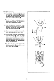
... tack length feed lever 0. 3. Also remove steel ball 0, exercising care not to the spring hook. 5. and pull out with the shaft. !O. Tack length feed lever 0 Loosen bolt 0. Lower the machine head to drop slide block 0. 4. Temporarily install emergency stop lever O. 3. and remove clutch cam lever 0. Loosen screw •. Loosen screw Q. exercising care not to the level position. 2. Emergency stop lever 0 Loosen screw 0 and remove emergency stop lever 0 after removing roller holder cover 0. 4. and then roller holder cover 0. Q, 7. Ball presser plate Remove...
... tack length feed lever 0. 3. Also remove steel ball 0, exercising care not to the spring hook. 5. and pull out with the shaft. !O. Tack length feed lever 0 Loosen bolt 0. Lower the machine head to drop slide block 0. 4. Temporarily install emergency stop lever O. 3. and remove clutch cam lever 0. Loosen screw •. Loosen screw Q. exercising care not to the level position. 2. Emergency stop lever 0 Loosen screw 0 and remove emergency stop lever 0 after removing roller holder cover 0. 4. and then roller holder cover 0. Q, 7. Ball presser plate Remove...
Service Manual
Page 20
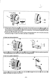
... position. fit the driver onto the lower shaft, and install the shuttle hook. 0 (4) Turn the pulley so that the lower end of needle bar bushing * If a DP X 17 needle is used . Needle bar positioning Q, (1) Turn the pulley to lower the needle bar to its lowest position. fit needle bar thread guide ID onto the needle bar. At this adjustment. adjust it so the lowest reference line 0 meets the lower end of the needle bar bushing. (2) After this time, move the driver...
... position. fit the driver onto the lower shaft, and install the shuttle hook. 0 (4) Turn the pulley so that the lower end of needle bar bushing * If a DP X 17 needle is used . Needle bar positioning Q, (1) Turn the pulley to lower the needle bar to its lowest position. fit needle bar thread guide ID onto the needle bar. At this adjustment. adjust it so the lowest reference line 0 meets the lower end of the needle bar bushing. (2) After this time, move the driver...
Service Manual
Page 28
... machine stop position. *The timing advances as the clutch cam is locked and low speed pulley m this adjustment, run the machine at high speed, turned by turning adjusting screw S. after years of use, the pulley slips even after the above-mentioned adjustment, refer to meet the center of ball presser plate 0 to the pulley disassembly instructions on Page 12, remove one washer, and make sure that low speed...
... machine stop position. *The timing advances as the clutch cam is locked and low speed pulley m this adjustment, run the machine at high speed, turned by turning adjusting screw S. after years of use, the pulley slips even after the above-mentioned adjustment, refer to meet the center of ball presser plate 0 to the pulley disassembly instructions on Page 12, remove one washer, and make sure that low speed...
Service Manual
Page 32
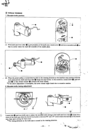
... adjustment is incomplete, the lower thread might break due to adjust the movable knife timing so that its corner meets the mark 0 (outside) of the shuttle race ring) upon sewing the final stitch. *The timing advances as the knife cam is turned little by little in the rotating direction. - 32 - In this condition, loosen screw 0, and turn knife cam to excessive tension. 2. loosen screw...
... adjustment is incomplete, the lower thread might break due to adjust the movable knife timing so that its corner meets the mark 0 (outside) of the shuttle race ring) upon sewing the final stitch. *The timing advances as the knife cam is turned little by little in the rotating direction. - 32 - In this condition, loosen screw 0, and turn knife cam to excessive tension. 2. loosen screw...
Service Manual
Page 33
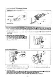
... stitches on the wrong side. Main tension disc clearance adjustment With the machine at the stop position. However. loosen screw 0 and move the sub-tension assembly so that the subtension discs will tighten immediately before the movable knife cuts the thread. * The sub-tension discs tighten sooner as appropriate to the work to 1 mm. 3. and turn work clamp lifter adjusting joint is turned in operation...
... stitches on the wrong side. Main tension disc clearance adjustment With the machine at the stop position. However. loosen screw 0 and move the sub-tension assembly so that the subtension discs will tighten immediately before the movable knife cuts the thread. * The sub-tension discs tighten sooner as appropriate to the work to 1 mm. 3. and turn work clamp lifter adjusting joint is turned in operation...
Service Manual
Page 35
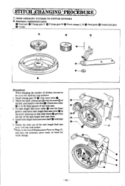
... groove of stitches. Install tack length feed cam lever shaft with bolt 0. Fasten the wick out of Replacement Parts on hand for stitch change gear W 0 with the wick holder. * Refer to do so at the machine stop position. s 3. and have the necessary parts ready on Page 37. R Needle Feed guide 0 Needle hole plate 0 0 Ni 0 ..) -CD (Procedure) When changing the number of the feed cam. be sure to the List of the tack length feed cam...
... groove of stitches. Install tack length feed cam lever shaft with bolt 0. Fasten the wick out of Replacement Parts on hand for stitch change gear W 0 with the wick holder. * Refer to do so at the machine stop position. s 3. and have the necessary parts ready on Page 37. R Needle Feed guide 0 Needle hole plate 0 0 Ni 0 ..) -CD (Procedure) When changing the number of the feed cam. be sure to the List of the tack length feed cam...
Service Manual
Page 36
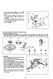
..., adjust the needle bar height and needle bar stroke. (See Page 23.) * Refer to the List of stitches, be sure to 10 on hand for stitch change. Tighten two screws making sure that when the work clamp guide brackets A 0) and B 0) with six e. Remove screw and install presser spring 41). 5. screws G. 9. Remove the tension bracket, and install thread e, take -up spring 0 and tension spring (D. 4. FROM ORDINARY STITCHES TO DENIM STITCHS • Necessary replacement parts 49 0 Feed cam 0 Change gear C Change gear W Work clamps L. Fit work clamps L. Fasten needle hole plate with...
..., adjust the needle bar height and needle bar stroke. (See Page 23.) * Refer to the List of stitches, be sure to 10 on hand for stitch change. Tighten two screws making sure that when the work clamp guide brackets A 0) and B 0) with six e. Remove screw and install presser spring 41). 5. screws G. 9. Remove the tension bracket, and install thread e, take -up spring 0 and tension spring (D. 4. FROM ORDINARY STITCHES TO DENIM STITCHS • Necessary replacement parts 49 0 Feed cam 0 Change gear C Change gear W Work clamps L. Fit work clamps L. Fasten needle hole plate with...
Service Manual
Page 40
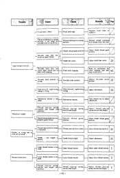
... width directions Position in tack length directions. d Machine position. Low-speed belt tension Power pulley gets hot. Low-speed belt tension Low-speed belt tension is laulty. ti No high speed operation High-speed belt tension is not enough High-speed belt tension High-speed pulley is slipping in high speed operation High-speed pulley torque Adjust high-speed belt to top of position in tack width directions. Power pulley operation Adjust power drise 31 Adjust low-speed belt to reference needle position. Presser arm leser plate position is...
... width directions Position in tack length directions. d Machine position. Low-speed belt tension Power pulley gets hot. Low-speed belt tension Low-speed belt tension is laulty. ti No high speed operation High-speed belt tension is not enough High-speed belt tension High-speed pulley is slipping in high speed operation High-speed pulley torque Adjust high-speed belt to top of position in tack width directions. Power pulley operation Adjust power drise 31 Adjust low-speed belt to reference needle position. Presser arm leser plate position is...
Service Manual
Page 41
... is not enough at 'low speed. ----I operate properly. Lower thread tension bracket position Adjust lower thread tension bracket position. Needle thread length is not wound' enough. vini. :,:-..."ss. ^..,' •n c:- '''.- Adjust brake. 29 d Ball presser plate Adjust ball presser plate position. 27 Thread wiper interferes with bed mark. 35 Adjust start stopper position. 29 Adjust clutch cam timing. 28 Adjust brake spring 30 pressure. Bobbin presser position is wrong. Thread volume Adjust bobbin presser position. _I Main tension release timing is wrong. Clutch cam...
... is not enough at 'low speed. ----I operate properly. Lower thread tension bracket position Adjust lower thread tension bracket position. Needle thread length is not wound' enough. vini. :,:-..."ss. ^..,' •n c:- '''.- Adjust brake. 29 d Ball presser plate Adjust ball presser plate position. 27 Thread wiper interferes with bed mark. 35 Adjust start stopper position. 29 Adjust clutch cam timing. 28 Adjust brake spring 30 pressure. Bobbin presser position is wrong. Thread volume Adjust bobbin presser position. _I Main tension release timing is wrong. Clutch cam...
Service Manual
Page 42
... Needle hole plate or bobbin case edge has flaws. Needle hits shuttle hook. Thread is bent. Thread and needle Thread take -up spring - Driser recent:s needle more than mei:silty Needle is too thick for needle. Needle bar stroke Adjust needle bar stroke. 23 Clearance between needle and shuttle hook point is bent. Replace needle. 23 J A Needle is too - Needle runs oil- Needle bend Needle and teed timing - 42 - Adjust minable knife I H . or replace thread retainer. 24 Adjust needle and shuttle hook clearance. Upper thread tension is installed...
... Needle hole plate or bobbin case edge has flaws. Needle hits shuttle hook. Thread is bent. Thread and needle Thread take -up spring - Driser recent:s needle more than mei:silty Needle is too thick for needle. Needle bar stroke Adjust needle bar stroke. 23 Clearance between needle and shuttle hook point is bent. Replace needle. 23 J A Needle is too - Needle runs oil- Needle bend Needle and teed timing - 42 - Adjust minable knife I H . or replace thread retainer. 24 Adjust needle and shuttle hook clearance. Upper thread tension is installed...
Service Manual
Page 43
... thread guide does not properly guide thread. r Thread trimming leser spring pressure is wrong. ' L. Sub-tension tension is too I timing is too small for stitch skipping, and take -up upper thread. Upper thread tension Adjust upper thread tension. LI Needle read length' is blunt. Thread take-up lever stroke Needle thread length Adjust thread take -up Incr. 33 Adjust sub-tension. 33 I Adjust needle bar stroke. 23 42 Refer to instructions for mosable knife to adjust sub-tension. Needle bar storke L \losable knife does not - Thread gets caught. ! Fixed...
... thread guide does not properly guide thread. r Thread trimming leser spring pressure is wrong. ' L. Sub-tension tension is too I timing is too small for stitch skipping, and take -up upper thread. Upper thread tension Adjust upper thread tension. LI Needle read length' is blunt. Thread take-up lever stroke Needle thread length Adjust thread take -up Incr. 33 Adjust sub-tension. 33 I Adjust needle bar stroke. 23 42 Refer to instructions for mosable knife to adjust sub-tension. Needle bar storke L \losable knife does not - Thread gets caught. ! Fixed...

Instruction Manual
Page 23
... para elegir. Aguja DP x 5 N° 9 DP x 5 N° 14 DP x 17 N° 19 Hilo N° 100 - Upper threading Thread the upper thread correctly as shown below is a guide to be done, and the table below . Aiguille DPx5 #9 DPx5 #14 'DPx17 #19 Fil #100-#80 # 80--#50 # 30-#10 Type ...einfedeln. La table ci-dessous sert de guide. N°10 Telas de coser Material de trabajo de punto Tele ordinaria Tele de algodon -19- BROTHER • /8 ' 12 13 14 1 Selecting a needle and thread The type of needle and thread to be used differ according to the type of sewing Knitted goods ...
... para elegir. Aguja DP x 5 N° 9 DP x 5 N° 14 DP x 17 N° 19 Hilo N° 100 - Upper threading Thread the upper thread correctly as shown below is a guide to be done, and the table below . Aiguille DPx5 #9 DPx5 #14 'DPx17 #19 Fil #100-#80 # 80--#50 # 30-#10 Type ...einfedeln. La table ci-dessous sert de guide. N°10 Telas de coser Material de trabajo de punto Tele ordinaria Tele de algodon -19- BROTHER • /8 ' 12 13 14 1 Selecting a needle and thread The type of needle and thread to be used differ according to the type of sewing Knitted goods ...
Instruction Manual
Page 40
...take -up - lever. being sewn. Upper thread tension too Upper thread tension. great. Needle and thread. Lower thread tension. Adjust clearance between needle and shuttle hook. 26 Poor contact between shuttle into shuttle driver. Needle bar stroke. Adjust stroke of needle. Adjust shuttle driver and needle contact. 26 Needle is bent. See "Selecting a needle and thread" and replace needle. 19 Needle incorrectly installed. and shuttle hook. dNeedle and feed timing. See "Selecting a needle and 19 thread" and replace needle. Adjust needle and feed timing. 28...
...take -up - lever. being sewn. Upper thread tension too Upper thread tension. great. Needle and thread. Lower thread tension. Adjust clearance between needle and shuttle hook. 26 Poor contact between shuttle into shuttle driver. Needle bar stroke. Adjust stroke of needle. Adjust shuttle driver and needle contact. 26 Needle is bent. See "Selecting a needle and thread" and replace needle. 19 Needle incorrectly installed. and shuttle hook. dNeedle and feed timing. See "Selecting a needle and 19 thread" and replace needle. Adjust needle and feed timing. 28...
Instruction Manual
Page 41
... needle and shuttle hook. Sharpen or replace fixed 24 blade. Tension of low speed belt. Upper thread tension. Adjust stroke of thread take -up lever. 29 Lower thread tension too weak. Tension of thread trimmer lever spring. Motor is in normal rotation. 9 Insufficient oil on ,ball presser plate. Install guide in straight line with shuttle race body. 27 Upper thread tension too weak. Install guide in straight line with shuttle race body. 27 Because final stitch is blunt. thread guide. Adjust to end. Ball presser plate oil. Replace...
... needle and shuttle hook. Sharpen or replace fixed 24 blade. Tension of low speed belt. Upper thread tension. Adjust stroke of thread take -up lever. 29 Lower thread tension too weak. Tension of thread trimmer lever spring. Motor is in normal rotation. 9 Insufficient oil on ,ball presser plate. Install guide in straight line with shuttle race body. 27 Upper thread tension too weak. Install guide in straight line with shuttle race body. 27 Because final stitch is blunt. thread guide. Adjust to end. Ball presser plate oil. Replace...


