
Brother International LK3-B430 Support Question
Brother International LK3-B430 Support Question
Find answers below for this question about Brother International LK3-B430.Need a Brother International LK3-B430 manual? We have 2 online manuals for this item!
Question posted by michelelhajj on October 11th, 2013
Spare Parts
i have a sewing machine number LK3-B430-2, and the power pulley assembly is damaged. the serial number of the part is 151930201. if you have a spare part , please contact me on my email address.
Best regards.
Current Answers
Related Brother International LK3-B430 Manual Pages
Service Manual - Page 1
NAGOYA, JAPAN SERVICE MANUAL FOR
BROTHER MODEL LK3-B430
.k.A"
c.o.% -ow G•
es
a
•
BROTHER INDUSTRIES, LTD.
Service Manual - Page 3
...
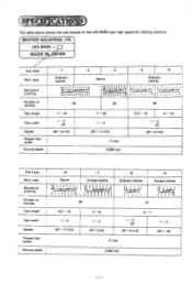
7 - 16
Tack width
1 - 2 (3)
Needle
DP x 5 #16
Presser foot stroke
Sewing speed 1
7 - 20 1- 3 DPx 17 #19
17 mm 2.000 rpm
6.5 - 16
4 - 10
1- 2 (3)
DP x 5 #16
Sub-class Main uses Decorative
Stitching
Number of the LK3-6430 type high speed bar tacking machine. t t't t t i 'I i i 1
-3
Denim
' /!'i iiiil
.tiii
IU
-4
-5
Ordinary clothes
ti r I i , .4.' 1
28
-8
1
Ordinary...
Service Manual - Page 6
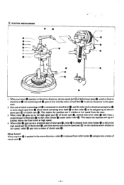
... moves onto gets into a recess of ball presser plate 0.
One end of steel ball 0 to convey the power to fall on the of feed came so
high speed part © of clutch cam This makes the machine sew 2 stitches at
e. (Stop
When
Lever) stop lver
(1)
is
pushed
in line with the center of clutch...
Service Manual - Page 7
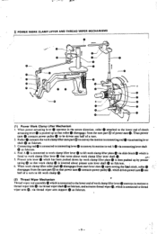
...Thus power cam 0 contacts power pulley 0 to be driven one
® (2) Thread Wiper Mechanism
Thread wiper rod assembly which...sewing the fiial stitch, roller
disengages from the cam part @ so that roller 0 disengage: from the cam part QQ of a turn .
2. POWER WORK CLAMP LIFTER AND THREAD WIPER MECHANISMS
0-
0
010
0
C
0-
0
O
(1) Power Work Clamp Lifter Mechanism
I. contacts power pulley...
Service Manual - Page 10
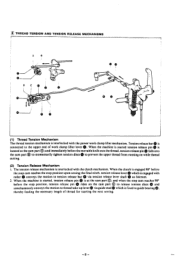
When the machine is started , tension release pin 0 is at the cam part 0; The tension release mechanism is interlocked with the power work clamp lifter lever 0. tension release pin 0 rides on while thread cutting.
(2)... thread for starting the next sewing.
0
-8- When the clutch is engaged 90° before
the stop cam reaches the stop position upon sewing the final stitch, tension release...
Service Manual - Page 11
... r - \N\
O
1.< 1 1
---
` •
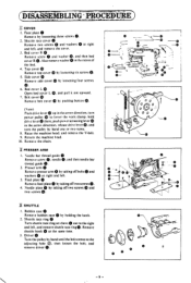
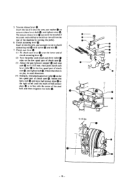
1 ai .' -- DISASSEMBLING PROCEDURE:
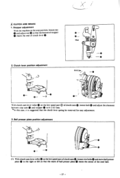
17 COVER
I . Q 7. Belt cover Remove belt cover by loosening four screws
6. turn the pulley by holding the latch.
2. push power actuating leverID
in the recess of the bed. 4. Return the machine head. 10. I
3 SHUTTLE
I . Shuttle race ring 0 Turn shuttle race ring set claws 0 out to lower the work clamp...
Service Manual - Page 12

... position, remove
screw 0 and washer 0, and then power pulley O.
2. Power pulley With the machine at the stop ring and washer 0, and then
®, • power cam together with drive lever (D. Also remove washer ... two screws (1) and washers
and then
tension relase bar plate 0. Ei POWER WORK CLAMP LIFTER
I . Main tension assembly 0
Loosen screw 0. Guide stud 0
Remove it by turning it with...
Service Manual - Page 14
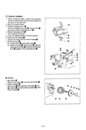
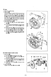
Thread trimming arm B 0 Pull it upward of spring 0. 7. Pulley assembly €0
Remove nut 0 (left-handed). Raise the machine head. 3. and remove knife cam
lever 0 together with connecting rod
PULLEY 1. Ball holder 0
Remove four screws 0, and then ball holder 0. 2. Also remove spring 0.
0
-0
0
0 -0
_
0-
0
(r(
J
0 0
0
- 12 - Knife cam lever spring 0 Unhook the knife cam lever end of...
Service Manual - Page 15
... screw 0.
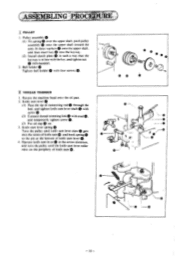
(3) Put oil cap 0 on the periphery of connecting rod 0 through the bed. SEM:MANG 1PROCIP)
I1 PULLEY
I . Knife cam lever 0
I ) Fit spring 0 over the upper shaft. Pulley assembly 0 ( I ) Pass the tip of knife cam O.
• 0
0 -'
O
-
-0
0
0
•
-13- push pulley assembly 0 onto the upper shaft toward the arm. fit three washers 0 onto the upper shaft.
Service Manual - Page 17
... the steel
ball.
and then retighten two bolts 0. Tension release lever
Insert the tip of the machine by turning the pulley.
6. and tighten screw Q. Check that there is in axial directions.
(4) Similarly, with screw and...roller to the left until clutch cam lever roller
rides on the
e low speed part of clutch
cam and tighten bolt m. 5. then push clutch cam
®. ...
Service Manual - Page 18
O
0-
0--
4 At.
- Power cam 0 ( I . IT FEED
1. Tack length feed lever 0 (I
0
•
0
- 16 -
Feed cam 0
With the stopper in contact with the stop cam (stop rings... 0 so that the mark ® of the feed cam meets the mark 0 of the feed cam. 3. Power pulley Install it with washer and screw
0 00 0 0 0 000 I I ) Fit slide block 0 onto tack...®. 2. Raise the machine head. 2.
Service Manual - Page 22
... O. and move the sub-tension in the
rotating direction at the machine stop
position.
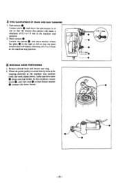
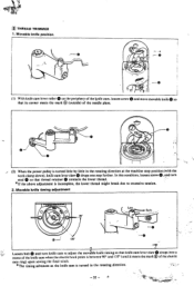
2. M MOVABLE KNIFE POSITIONING
I . loosen screw O....contacts the lower thread.
In this condition. I91 DISC CLEARANCES OF MAIN AND SUB TENSIONS
©. When the power pulley is turned little by little in or
out so that the tension disc presser will make a
clearance of 0.5 to 1.0 mm at the machine...
Service Manual - Page 26
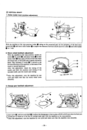
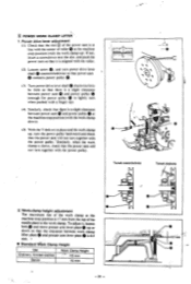
Worm wheel backlash adjustment With the machine at the stop position (roller 0 riding on the projected part on the periphery of 0.02 to 0.05 mm when the clutch cam, or the knife cam is moved in the forward direction of the movable ...
Service Manual - Page 27
...; 0.5 mm. * In this case. Ball presser plate position adjustment
0
•••
0
- 0
(I ) With clutch cam lever roller 0 on the low speed part 0 of clutch cam O. Stopper adjustment With the machine at the stop cam 0 and stopper to the right or left so that the mark of ball presser plate 0 meets the center...
Service Manual - Page 30
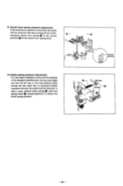
...very heavy material is sewn with the machine of the clutch lever spring hook.
10. unhook brake spring 0, and turn all the way to the stop position upon sewing the last stitch due to reduce the...adjustment If the clutch lever operates so hard that the clutch will not positively fall upon sewing the last stitch, reconnect clutch lever spring to the second position of the standard specifications,...
Service Manual - Page 31
... there is a slight clearance between power cam 0 and power pulley 0 (enough for power pulley 0 to the work clamp up . and turn power drive lever shaft Q counterclockwise so that power cam 0 contacts power pulley 0.
13) Turn power drive lever shaft 0 clockwise little by little so that tiere is l7 mm from the top of roller 0 at the machine stop position (with the center...
Service Manual - Page 32
...contacts the lower thread.
* If the above adjustment is incomplete, the lower thread might break due to adjust the movable knife timing so that its corner meets the mark 0 (outside) of the needle plate.
-r
(2) When the power pulley is turned in the rotating direction at the machine...0 on the periphery of the shuttle race ring) upon sewing the final stitch.
*The timing advances as the knife cam...
Service Manual - Page 35
...parts ready on Page 37. R Needle
Feed guide 0 Needle hole plate
0
0
Ni
0
..)
-CD
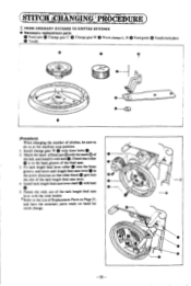
(Procedure) When changing the number... of the feed cam. Install tack length feed cam lever shaft with bolt 0. Install change .
0
_0 -35- Fasten the wick out of Replacement Parts... FROM ORDINARY STITCHES TO KNITTED STITCHES
• Necessary replacement parts
Feed cam 0 Change gear C Change gear W Work ...
Service Manual - Page 40
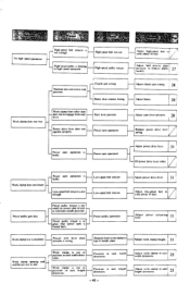
... operation
Adjust clutch cant timing
Adjust brake.
29
Adjust start leser.
Low-speed belt tension
Power pulley gets hot. d Machine position.
cam
operation
is too small for power cam to turn to
slop
rI -
Presser arm leser plate position is out of needle plate
Adjust work clamp in tack length directions
- 40 - c_lWork ...
Instruction Manual - Page 5
... speed bar tacking machine.
la ,. 11 ../ 3
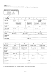
7 s 7 '4, 27 ,3 I . Kinds of machines The table below shows the sub-classes of stitches Tack length
Tack width
Needle Presser foot stroke Sewing speed
-6
Denim
. 121n ti "1:If1I4' .15,4I!4I/Ii
. BROTHER INDUSTRIES, LTD.
LK3-B43O / 1:=1 MADE IN JAPAN
ir Sub-class
Main uses
Decorative stitching
Number of stitches...
Similar Questions

La Máquina De Hacer Presillas No Me Corta El Hilo.
La máquina de presillas no me corta el hilo.,
La máquina de presillas no me corta el hilo.,
(Posted by info42861 2 years ago)

Why Is My Machine Lk3 B430-2 Is In Continus Sikle How Can I Vorrect It
(Posted by Frizschulz 10 years ago)

Brother Lk3-b430 It Is Not Switching To High Speed To Operate Properly
(Posted by nelhera141 10 years ago)


Can't Get My Machine To Do Anything Beyond Powering Up.....
I have this machine. It will power up but I can't get it to do anything else. Thought I would ask yo...
I have this machine. It will power up but I can't get it to do anything else. Thought I would ask yo...
(Posted by haneycl 13 years ago)