
Programmer Instruction Manual - English
Page 3
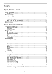
... input ...27 Lines ...29 Curve ...31 Double stitch...34 Feed ...36 Basting...38 Symmetrical pattern...41 Splitting...44 Zigzag stitch ...46 Multiple stitch...48 Example of modified program...52 Resizing pattern...52 Changing partially ...54 Deleting the first stitch ...57 Changing the first stitch position...59 Adding sewing point before the first stitch ...62 Adding escape point before the first stitch ...65 Moving the escape point...68...
... input ...27 Lines ...29 Curve ...31 Double stitch...34 Feed ...36 Basting...38 Symmetrical pattern...41 Splitting...44 Zigzag stitch ...46 Multiple stitch...48 Example of modified program...52 Resizing pattern...52 Changing partially ...54 Deleting the first stitch ...57 Changing the first stitch position...59 Adding sewing point before the first stitch ...62 Adding escape point before the first stitch ...65 Moving the escape point...68...

Programmer Instruction Manual - English
Page 5
... a multiple stitch ...173 Creating double stitch ...175 Parallel stitch ...176 Offset ...177 Creating feed data ...178 Creating split data...179 Creating magnified data...179 Low-speed sewing ...180 Setting the option output...181 Ending programming ...181 Editing data ...182 Moving symmetrically to the Y axis...182 Moving symmetrically to the X axis...182 Moving symmetrically to a point...183 Rotating a pattern clockwise...
... a multiple stitch ...173 Creating double stitch ...175 Parallel stitch ...176 Offset ...177 Creating feed data ...178 Creating split data...179 Creating magnified data...179 Low-speed sewing ...180 Setting the option output...181 Ending programming ...181 Editing data ...182 Moving symmetrically to the Y axis...182 Moving symmetrically to the X axis...182 Moving symmetrically to a point...183 Rotating a pattern clockwise...

Parts Manual - English
Page 3
Feed mechanism 7 C2. Bobbin winder mechanism ......... 25 J. Thread wiper mechanism 31 L. Thread nipper mechanism . . 33 N. Synchronizer 35 P. Operation panel mechanism 49 U. Machine body 1 Bl. Upper shaft and needle bar mechanism 5 C1. Threading mechanism . 23 H. Control box mechanism 37 Q2. Power table 53 W. Diifferent Pads list 60 Sp2. Lower shaft mechanism 17 F. Thread take-up mechanism 31 M. Air pressure mechanism . 45 S. Accessories • 57 Sp1. Feed mechanism (Option parts) 13 D. Foot switch pedal mechanism (Option...
Feed mechanism 7 C2. Bobbin winder mechanism ......... 25 J. Thread wiper mechanism 31 L. Thread nipper mechanism . . 33 N. Synchronizer 35 P. Operation panel mechanism 49 U. Machine body 1 Bl. Upper shaft and needle bar mechanism 5 C1. Threading mechanism . 23 H. Control box mechanism 37 Q2. Power table 53 W. Diifferent Pads list 60 Sp2. Lower shaft mechanism 17 F. Thread take-up mechanism 31 M. Air pressure mechanism . 45 S. Accessories • 57 Sp1. Feed mechanism (Option parts) 13 D. Foot switch pedal mechanism (Option...
Instruction Manual - English
Page 4
... the machine develops a problem, contact your nearest Brother dealer or a qualified technician. Keep the oil out of the reach of the electrical system. Be sure to its original position. Set the needle to the machine. If this could result in injury. • When threading the needle • When replacing the needle and bobbin • When not using the machine and when leaving the machine unattended If using a work table...
... the machine develops a problem, contact your nearest Brother dealer or a qualified technician. Keep the oil out of the reach of the electrical system. Be sure to its original position. Set the needle to the machine. If this could result in injury. • When threading the needle • When replacing the needle and bobbin • When not using the machine and when leaving the machine unattended If using a work table...

Instruction Manual - English
Page 6
... 9-17. Clearing all memory settings 49 10. TROUBLESHOOTING 63 16. Power table 3 3-2. Installing the foot switch 13 3-17. Cleaning the control box air inlet port 38 8-6. Panel DIP switch functions 50 10-2. Adjusting the shuttle race thread guide 40 9-6. Lubrication points 16 5. Using the bobbin thread counter 25 5-11. Adjusting the needle clearance 40 9-5. Adjustment of air pressure 47 9-15. CONTENTS 1. Installing the machine head 6 3-8. Installing the belt cover 13 3-16. Checking the...
... 9-17. Clearing all memory settings 49 10. TROUBLESHOOTING 63 16. Power table 3 3-2. Installing the foot switch 13 3-17. Cleaning the control box air inlet port 38 8-6. Panel DIP switch functions 50 10-2. Adjusting the shuttle race thread guide 40 9-6. Lubrication points 16 5. Using the bobbin thread counter 25 5-11. Adjusting the needle clearance 40 9-5. Adjustment of air pressure 47 9-15. CONTENTS 1. Installing the machine head 6 3-8. Installing the belt cover 13 3-16. Checking the...
Instruction Manual - English
Page 8
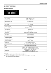
... be used. KE-436C 2 2. SPECIFICATIONS Stitch formation Maximum sewing speed Maximum pattern size Feed mechanism Stitch length Number of stitches Maximum stitch number Work clamp lifter Work clamp height Rotary hook Wiper device Thread trimmer device Thread take-up to a maximum size of small articles, curtain darts, etc. Shuttle hook (shuttle hook 2, optional) Standard equipment Standard equipment Standard equipment 18 mm 0 mm, 3 - 8 mm built-in stopping mechanism 3.5 floppy disk 2HD / 1.44MB, 2DD Three-phase 400W induction motor Weights Power source Machine...
... be used. KE-436C 2 2. SPECIFICATIONS Stitch formation Maximum sewing speed Maximum pattern size Feed mechanism Stitch length Number of stitches Maximum stitch number Work clamp lifter Work clamp height Rotary hook Wiper device Thread trimmer device Thread take-up to a maximum size of small articles, curtain darts, etc. Shuttle hook (shuttle hook 2, optional) Standard equipment Standard equipment Standard equipment 18 mm 0 mm, 3 - 8 mm built-in stopping mechanism 3.5 floppy disk 2HD / 1.44MB, 2DD Three-phase 400W induction motor Weights Power source Machine...

Instruction Manual - English
Page 10
board mounting plate (3)). Close the covers (panel mounting assembly (2) and main P.C. Secure the power switch cord with the screws (1). * The main P.C. board mounting plate (3) will be used with the four accessory bolts (4), spacers (5), flat washers (6) and nuts (7) as shown in the illustration). (KE series machine heads can only be opened again during "3-13. KE-436C 4 Install the control box with control boxes which have the IM sticker attached.) Spacers...
board mounting plate (3)). Close the covers (panel mounting assembly (2) and main P.C. Secure the power switch cord with the screws (1). * The main P.C. board mounting plate (3) will be used with the four accessory bolts (4), spacers (5), flat washers (6) and nuts (7) as shown in the illustration). (KE series machine heads can only be opened again during "3-13. KE-436C 4 Install the control box with control boxes which have the IM sticker attached.) Spacers...

Instruction Manual - English
Page 16
... screws (5), and then open the control box cover (main P.C. 3. Then re-tighten the screw (9) so that the cords do not get pulled when the machine head is secured as shown in the direction of pins Head position switch 9-pin X, Y, Sewing sensor 12-pin Synchronizer Machine specification select connector Thread wiper solenoid Thread take-up solenoid Presser solenoid Thread trimmer solenoid Pulse motor, Y 5-pin 8-pin 5-pin 4-pin 4-pin (blue) Pulse motor, X 4-pin Operation panel 10-pin Upper shaft motor 3-pin EMERGENCY STOP switch 6-pin...
... screws (5), and then open the control box cover (main P.C. 3. Then re-tighten the screw (9) so that the cords do not get pulled when the machine head is secured as shown in the direction of pins Head position switch 9-pin X, Y, Sewing sensor 12-pin Synchronizer Machine specification select connector Thread wiper solenoid Thread take-up solenoid Presser solenoid Thread trimmer solenoid Pulse motor, Y 5-pin 8-pin 5-pin 4-pin 4-pin (blue) Pulse motor, X 4-pin Operation panel 10-pin Upper shaft motor 3-pin EMERGENCY STOP switch 6-pin...

Instruction Manual - English
Page 24
... sewing after replacing the bobbin thread. Used to "5-9. Using the bobbin thread counter".) (15) TEST switch Used to move the feed mechanism only in the bobbin thread counter to reset error displays. switch (An alarm will sound when the counter reads . Sewing is pressed. (17) STEP BACK switch Used when winding a fresh bobbin, or when correcting a stitch pattern due to a broken (RESET switch) needle thread. Also used to floppy disk. (14) Bobbin Thread CHANGE ....... KE-436C 18 Illuminates when bobbin thread...
... sewing after replacing the bobbin thread. Used to "5-9. Using the bobbin thread counter".) (15) TEST switch Used to move the feed mechanism only in the bobbin thread counter to reset error displays. switch (An alarm will sound when the counter reads . Sewing is pressed. (17) STEP BACK switch Used when winding a fresh bobbin, or when correcting a stitch pattern due to a broken (RESET switch) needle thread. Also used to floppy disk. (14) Bobbin Thread CHANGE ....... KE-436C 18 Illuminates when bobbin thread...
Instruction Manual - English
Page 31
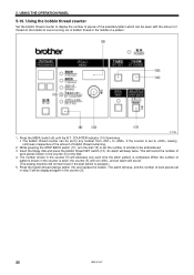
... middle of bobbin thread in the counter (5). 25 KE-436C The alarm will record the number of work pieces set to avoid running out of a pattern. 2703Q 1. Using the bobbin thread counter Set the bobbin thread counter to the disk. 4. Insert the floppy disk and press the bobbin thread SET switch (13). 5. This will stop, and the number of the selected pattern which can be embroidered. 3. When the number of patterns shown in...
... middle of bobbin thread in the counter (5). 25 KE-436C The alarm will record the number of work pieces set to avoid running out of a pattern. 2703Q 1. Using the bobbin thread counter Set the bobbin thread counter to the disk. 4. Insert the floppy disk and press the bobbin thread SET switch (13). 5. This will stop, and the number of the selected pattern which can be embroidered. 3. When the number of patterns shown in...

Instruction Manual - English
Page 36
... bobbin presser (1). 3. To wind more while pressing and holding the STEP BACK switch (3). 2713Q 6. KE-436C Case A Case B 2531Q 2532Q 30 The bobbin presser (1) will illuminate.) 4. Release the foot switch (2). 8. Remove the bobbin, hook the thread onto the knife (4), and then pull the bobbin in the direction of the arrow to its original position after the machine starts operating. 6. Check that the needle is completed, depress it winds on the operation panel will automatically...
... bobbin presser (1). 3. To wind more while pressing and holding the STEP BACK switch (3). 2713Q 6. KE-436C Case A Case B 2531Q 2532Q 30 The bobbin presser (1) will illuminate.) 4. Release the foot switch (2). 8. Remove the bobbin, hook the thread onto the knife (4), and then pull the bobbin in the direction of the arrow to its original position after the machine starts operating. 6. Check that the needle is completed, depress it winds on the operation panel will automatically...

Instruction Manual - English
Page 37
... the thread through the lever thread hole (4), and then pull out approximately 30 mm of the arrow when the thread is depressed by mistake, which could result in the direction of thread. 6-6. Replacing the bobbin case and threading the thread CAUTION Turn off the power switch before removing or inserting the bobbin case, otherwise the machine may need to open it out from the thread hole (3). Sewing conditions and thread tension Use Upper thread Lower thread Medium materials Standard hook #50...
... the thread through the lever thread hole (4), and then pull out approximately 30 mm of the arrow when the thread is depressed by mistake, which could result in the direction of thread. 6-6. Replacing the bobbin case and threading the thread CAUTION Turn off the power switch before removing or inserting the bobbin case, otherwise the machine may need to open it out from the thread hole (3). Sewing conditions and thread tension Use Upper thread Lower thread Medium materials Standard hook #50...
Instruction Manual - English
Page 40
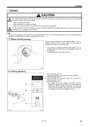
... replacing the needle and bobbin • When not using the machine and when leaving the machine unattended Do not touch any of shipment from the factory, this may operate if the foot switch is between the marks (2) on ) 7-2. Press the PRO. Press R/W switch (3). • The floppy disk drive indicator will blink the program number. 2718Q 2719Q KE-436C 34 Sewing operation 2462Q 1. SEWING CAUTION...
... replacing the needle and bobbin • When not using the machine and when leaving the machine unattended Do not touch any of shipment from the factory, this may operate if the foot switch is between the marks (2) on ) 7-2. Press the PRO. Press R/W switch (3). • The floppy disk drive indicator will blink the program number. 2718Q 2719Q KE-436C 34 Sewing operation 2462Q 1. SEWING CAUTION...
Instruction Manual - English
Page 64
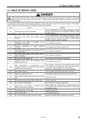
... align timing mark with the sewing machine, a buzzer will sound and an error code will appear in sewing data. E.12 Emergency stop switch was depressed, or connection of start switch is defective. is not securely connected. of model selection Turn off the power switch and disconnecting the power cord from the wall outlet before opening the face plate of cords inside sewing machine motor has operated. E.14 Foot switch...
... align timing mark with the sewing machine, a buzzer will sound and an error code will appear in sewing data. E.12 Emergency stop switch was depressed, or connection of start switch is defective. is not securely connected. of model selection Turn off the power switch and disconnecting the power cord from the wall outlet before opening the face plate of cords inside sewing machine motor has operated. E.14 Foot switch...

Instruction Manual - English
Page 69
... 41 63 KE-436C clamp lubrication the work clamp lift amount. Thread wiper does not operate correctly. Bobbin presser position is too short. Adjust the position of presser arm lever plate. Thread stroke take-up lever Adjust the thread take-up lever stroke. Problem Cause Check Remedy Work clamp does not Work clamp operation is incorrect. Thread wiper position Adjust the operating distance of the thread wiper. Thread comes un- upper thread Upper thread length Adjust the sub-tension. Work clamp lift amount is obstructing the needle. The thread wiper is too...
... 41 63 KE-436C clamp lubrication the work clamp lift amount. Thread wiper does not operate correctly. Bobbin presser position is too short. Adjust the position of presser arm lever plate. Thread stroke take-up lever Adjust the thread take-up lever stroke. Problem Cause Check Remedy Work clamp does not Work clamp operation is incorrect. Thread wiper position Adjust the operating distance of the thread wiper. Thread comes un- upper thread Upper thread length Adjust the sub-tension. Work clamp lift amount is obstructing the needle. The thread wiper is too...

Instruction Manual - English
Page 70
... incorrectly. Needle bar lift amount. 15. Upper thread tension Adjust the upper thread tension. Thread take -up spring tension and height are damaged. Adjust the needle clearance Incorrect needle rotary hook timing. Needle and thread Use the correct needle for the needle. Page 32 29 29 33 66 32 40 39 40 Needle breaks. Needle direction Install the needle correctly. 29 Needle clearance Needle is too great. Clearance between driver and needle Adjust the driver needle guard. KE-436C 64 Lower thread tension is too strong. TROUBLESHOOTING Problem Cause...
... incorrectly. Needle bar lift amount. 15. Upper thread tension Adjust the upper thread tension. Thread take -up spring tension and height are damaged. Adjust the needle clearance Incorrect needle rotary hook timing. Needle and thread Use the correct needle for the needle. Page 32 29 29 33 66 32 40 39 40 Needle breaks. Needle direction Install the needle correctly. 29 Needle clearance Needle is too great. Clearance between driver and needle Adjust the driver needle guard. KE-436C 64 Lower thread tension is too strong. TROUBLESHOOTING Problem Cause...

Instruction Manual - English
Page 71
... Needle bar lift amount Adjust the needle bar lift amount. Thread stroke take-up lever Adjust the thread take -up lever stroke. Uneven length. The movable knife does not pick up the thread because of the shuttle race thread guide. Poor seam finish on and foot switch is not separating the threads. Movable knife is incorrect. Thread jamming. Upper thread is blunt. Fixed knife is too long. Head position switch is not trimmed. TROUBLESHOOTING Problem...
... Needle bar lift amount Adjust the needle bar lift amount. Thread stroke take-up lever Adjust the thread take -up lever stroke. Uneven length. The movable knife does not pick up the thread because of the shuttle race thread guide. Poor seam finish on and foot switch is not separating the threads. Movable knife is incorrect. Thread jamming. Upper thread is blunt. Fixed knife is too long. Head position switch is not trimmed. TROUBLESHOOTING Problem...

Instruction Manual - English
Page 72
... as rotary type or fiber type, stops sewing when a thread breakage is a pedal-type foot switch. OPTIONAL PARTS Two-step foot switch Liquid cooling tank Three-pedal foot switch Work clamp plate, OT Programmer assy Thread breakage detector device Needle cooler device Air wiper device 2-step thread tension device 16. KE-436C 66 It can also be switched between two settings at high sewing speeds. OPTIONAL PARTS This is detected and warns the operator. 16.
... as rotary type or fiber type, stops sewing when a thread breakage is a pedal-type foot switch. OPTIONAL PARTS Two-step foot switch Liquid cooling tank Three-pedal foot switch Work clamp plate, OT Programmer assy Thread breakage detector device Needle cooler device Air wiper device 2-step thread tension device 16. KE-436C 66 It can also be switched between two settings at high sewing speeds. OPTIONAL PARTS This is detected and warns the operator. 16.
Hand Book - English
Page 1
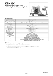
... with Stepping Foot and Programming function Specifications Stitch formation Maximum sewing speed Maximum pattern size (X x Y) Feed mechanism Stitch length No. For plain stitching of stitches Work clamp lifter Work clamp height Rotary hook Wiper device Thread trimmer device Thread take-up to a maximum size of 100 mm x 60 mm can be sewn. of stitches Maximum number of small articles, curtain darts, etc. *Two-stage work clamp, light work clamp and inner clamping device (optional) can be used. Shuttle hook (Shuttle hook 2, optional) Standard...
... with Stepping Foot and Programming function Specifications Stitch formation Maximum sewing speed Maximum pattern size (X x Y) Feed mechanism Stitch length No. For plain stitching of stitches Work clamp lifter Work clamp height Rotary hook Wiper device Thread trimmer device Thread take-up to a maximum size of 100 mm x 60 mm can be sewn. of stitches Maximum number of small articles, curtain darts, etc. *Two-stage work clamp, light work clamp and inner clamping device (optional) can be used. Shuttle hook (Shuttle hook 2, optional) Standard...

Inner Clamping Device Instruction Manual - English
Page 8
... the power cord until the needle of the control box. Remove the work clamp guide plates (1), and detach the work clamp, 434E air (2) together with work clamp (3). 2. Replace the feed plate (4) with the feed plate that was made in injury. INSTALLATION 危険 / DANGER 5 Wait at least 5 minutes after turning off the power switch and disconnecting the power cord from the wall outlet before opening the face plate of the pressure gauge points to make the feed plate...
... the power cord until the needle of the control box. Remove the work clamp guide plates (1), and detach the work clamp, 434E air (2) together with work clamp (3). 2. Replace the feed plate (4) with the feed plate that was made in injury. INSTALLATION 危険 / DANGER 5 Wait at least 5 minutes after turning off the power switch and disconnecting the power cord from the wall outlet before opening the face plate of the pressure gauge points to make the feed plate...


