
Service Manual
Page 104
Printer AC cord HL-5130/5140/5150D/5150DN Service Manual Fig. 4-1 3.2 Drum Unit (1) Open the front cover and remove the drum unit. Drum unit Front cover Fig. 4-2 4-3 3. DISASSEMBLY PROCEDURE 3.1 AC Cord (1) Disconnect the AC cord from the printer.
Printer AC cord HL-5130/5140/5150D/5150DN Service Manual Fig. 4-1 3.2 Drum Unit (1) Open the front cover and remove the drum unit. Drum unit Front cover Fig. 4-2 4-3 3. DISASSEMBLY PROCEDURE 3.1 AC Cord (1) Disconnect the AC cord from the printer.

Service Manual
Page 106
Paper pick-up roller Grease: Molykote PG-662Y (4 mm dia.ball) Paper tray Fig. 4-5 (4) Remove the four bind B M4x12 Taptite screws, and then remove the paper tray front cover. HL-5130/5140/5150D/5150DN Service Manual NOTE: When replacing/re-assembling the pad holder ZL2 ASSY, remove the old grease and apply a suitable amount of grease referring to the figure below; Paper tray Taptite, bind B M4x12 Hook Taptite, bind B M4x12 Hook Fig. 4-6 Paper tray front cover 4-5
Paper pick-up roller Grease: Molykote PG-662Y (4 mm dia.ball) Paper tray Fig. 4-5 (4) Remove the four bind B M4x12 Taptite screws, and then remove the paper tray front cover. HL-5130/5140/5150D/5150DN Service Manual NOTE: When replacing/re-assembling the pad holder ZL2 ASSY, remove the old grease and apply a suitable amount of grease referring to the figure below; Paper tray Taptite, bind B M4x12 Hook Taptite, bind B M4x12 Hook Fig. 4-6 Paper tray front cover 4-5

Service Manual
Page 110
HL-5130/5140/5150D/5150DN Service Manual (15) Unhook the two catches (A) of the pressure plate while pulling the plastic frame outwards, then unhook the other two catches (B) of the plate while pulling the plastic frame outwards to remove the two pressure plate springs. Paper tray Pressure plate spring Pressure plate spring Fig. 4-14 4-9 Hook Catches (A) Pressure plate ASSY Paper tray Catch (B) Plastic frame Fig. 4-13 (16) Unhook the pressure plate spring from the plastic hook to remove the pressure plate ASSY.
HL-5130/5140/5150D/5150DN Service Manual (15) Unhook the two catches (A) of the pressure plate while pulling the plastic frame outwards, then unhook the other two catches (B) of the plate while pulling the plastic frame outwards to remove the two pressure plate springs. Paper tray Pressure plate spring Pressure plate spring Fig. 4-14 4-9 Hook Catches (A) Pressure plate ASSY Paper tray Catch (B) Plastic frame Fig. 4-13 (16) Unhook the pressure plate spring from the plastic hook to remove the pressure plate ASSY.

Service Manual
Page 112
Taptite, cup B M3x8 Side guide gear Friction spring Side guide rack Side guide rack Fig. 4-16 (21) Remove the paper indicator. Paper tray Paper indicator Fig. 4-17 4-11 HL-5130/5140/5150D/5150DN Service Manual (19) Remove the cup B M3x8 Taptite screw, and then remove the side guide gear and the friction spring. (20) Remove the two side guide racks.
Taptite, cup B M3x8 Side guide gear Friction spring Side guide rack Side guide rack Fig. 4-16 (21) Remove the paper indicator. Paper tray Paper indicator Fig. 4-17 4-11 HL-5130/5140/5150D/5150DN Service Manual (19) Remove the cup B M3x8 Taptite screw, and then remove the side guide gear and the friction spring. (20) Remove the two side guide racks.
Service Manual
Page 114
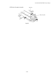
HL-5130/5140/5150D/5150DN Service Manual Paper tray 1 Fig. 4-20 1 Paper rear guide 2 4-13 (24) Remove the paper rear guide.
HL-5130/5140/5150D/5150DN Service Manual Paper tray 1 Fig. 4-20 1 Paper rear guide 2 4-13 (24) Remove the paper rear guide.

Service Manual
Page 116
Pressure roller spring Pressure roller Tray feed ZL2 Fig. 4-23 (4) Remove the two bind B M3x8 Taptite screws, and then remove the guide plate stopper. (5) Remove the two left guide spring 2. HL-5130/5140/5150D/5150DN Service Manual NOTE: Set pressure roller, and assemble pressure roller spring after assembling DX roller holder. Guide plate stoller Left guide spring 2 Taptite, bind B M3x8 Guide plate stopper Taptite, bind B M3x8 Left guide spring 2 Tray feed ZL2 Fig. 4-24 4-15 Left guide spring 2
Pressure roller spring Pressure roller Tray feed ZL2 Fig. 4-23 (4) Remove the two bind B M3x8 Taptite screws, and then remove the guide plate stopper. (5) Remove the two left guide spring 2. HL-5130/5140/5150D/5150DN Service Manual NOTE: Set pressure roller, and assemble pressure roller spring after assembling DX roller holder. Guide plate stoller Left guide spring 2 Taptite, bind B M3x8 Guide plate stopper Taptite, bind B M3x8 Left guide spring 2 Tray feed ZL2 Fig. 4-24 4-15 Left guide spring 2

Service Manual
Page 118
3.5 Access Cover (1) Remove the access cover. Rear cover C Taptite, bind B M4x12 Fig. 4-28 4-17 Access cover HL-5130/5140/5150D/5150DN Service Manual Fig. 4-27 3.6 Rear Cover C (1) Remove the bind B M4x12 Taptite screw, and then remove the rear cover C.
3.5 Access Cover (1) Remove the access cover. Rear cover C Taptite, bind B M4x12 Fig. 4-28 4-17 Access cover HL-5130/5140/5150D/5150DN Service Manual Fig. 4-27 3.6 Rear Cover C (1) Remove the bind B M4x12 Taptite screw, and then remove the rear cover C.

Service Manual
Page 120
Hook Rear cover MP ASSY Fig. 4-30 (2) Remove the outer chute MP ASSY. Outer chute MP ASSY Hook Fig. 4-31 4-19 HL-5130/5140/5150D/5150DN Service Manual 3.8 Rear Cover MP ASSY / Outer Chute MP ASSY (HL-5150D/5170DN) (1) Remove the rear cover MP ASSY.
Hook Rear cover MP ASSY Fig. 4-30 (2) Remove the outer chute MP ASSY. Outer chute MP ASSY Hook Fig. 4-31 4-19 HL-5130/5140/5150D/5150DN Service Manual 3.8 Rear Cover MP ASSY / Outer Chute MP ASSY (HL-5150D/5170DN) (1) Remove the rear cover MP ASSY.

Service Manual
Page 122
HL-5130/5140/5150D/5150DN Service Manual 3.10 Side Cover L/R (1) Remove the three bind B M4x12 Taptite screws, and then remove the side cover R. Taptite, bind B M4x12 Hook Hooks Side cover R Hook Hooks Taptite, bind B M4x12 Fig. 4-34 (2) Remove the four bind B M4x12 Taptite screws, and then remove the side cover L. Side cover L Taptite, bind B M4x12 Fig. 4-35 4-21
HL-5130/5140/5150D/5150DN Service Manual 3.10 Side Cover L/R (1) Remove the three bind B M4x12 Taptite screws, and then remove the side cover R. Taptite, bind B M4x12 Hook Hooks Side cover R Hook Hooks Taptite, bind B M4x12 Fig. 4-34 (2) Remove the four bind B M4x12 Taptite screws, and then remove the side cover L. Side cover L Taptite, bind B M4x12 Fig. 4-35 4-21

Service Manual
Page 124
HL-5130/5140/5150D/5150DN Service Manual (4) Remove the two cup B M3x8 Taptite screws, and then remove the panel PCB ASSY. (5) Remove the SW key A, the SW key B and the panel light guide from the panel guide. Panel light guide 2 Diffusion film Panel light guide Fig. 4-39 4-23 SW key B Top cover ASSY Panel light guide Panel PCB ASSY Taptite, cup B M3x8 SW key A Fig. 4-38 (6) Remove the panel light guide 2 and the diffusion film from the top cover ASSY.
HL-5130/5140/5150D/5150DN Service Manual (4) Remove the two cup B M3x8 Taptite screws, and then remove the panel PCB ASSY. (5) Remove the SW key A, the SW key B and the panel light guide from the panel guide. Panel light guide 2 Diffusion film Panel light guide Fig. 4-39 4-23 SW key B Top cover ASSY Panel light guide Panel PCB ASSY Taptite, cup B M3x8 SW key A Fig. 4-38 (6) Remove the panel light guide 2 and the diffusion film from the top cover ASSY.

Service Manual
Page 126
Corrugation pinch roller L, R Pinch roller holder Inner chute Fig. 4-42 3.12 Front Cover ASSY (HL-5130/5140) (1) Release the link. (2) Remove the front cover ASSY. Frame Link Front cover ASSY Fig. 4-43 4-25 HL-5130/5140/5150D/5150DN Service Manual (9) Remove the corrugation pinch roller L, R and pinch roller holder.
Corrugation pinch roller L, R Pinch roller holder Inner chute Fig. 4-42 3.12 Front Cover ASSY (HL-5130/5140) (1) Release the link. (2) Remove the front cover ASSY. Frame Link Front cover ASSY Fig. 4-43 4-25 HL-5130/5140/5150D/5150DN Service Manual (9) Remove the corrugation pinch roller L, R and pinch roller holder.

Service Manual
Page 128
HL-5130/5140/5150D/5150DN Service Manual (7) While pushing the MP pressure plate, remove the separation plate ASSY. Double faced tape Fig. 4-47 Separation plate ASSY 4-27 Separation plate ASSY MP chute ASSY MP pressure plate Fig. 4-46 NOTE: When replacing with the new separation plate ASSY, attach it after peeling the cover paper of double-faced tape.
HL-5130/5140/5150D/5150DN Service Manual (7) While pushing the MP pressure plate, remove the separation plate ASSY. Double faced tape Fig. 4-47 Separation plate ASSY 4-27 Separation plate ASSY MP chute ASSY MP pressure plate Fig. 4-46 NOTE: When replacing with the new separation plate ASSY, attach it after peeling the cover paper of double-faced tape.

Service Manual
Page 130
HL-5130/5140/5150D/5150DN Service Manual MP chute ASSY MP tray ASSY Fig. 4-50 (11) Remove the MP paper guide 2 and the MP paper guide 3 from the MP tray ASSY. MP paper guide 3 MP paper guide 2 MP tray ASSY Fig. 4-51 4-29 (10) Remove the MP tray ASSY.
HL-5130/5140/5150D/5150DN Service Manual MP chute ASSY MP tray ASSY Fig. 4-50 (11) Remove the MP paper guide 2 and the MP paper guide 3 from the MP tray ASSY. MP paper guide 3 MP paper guide 2 MP tray ASSY Fig. 4-51 4-29 (10) Remove the MP tray ASSY.

Service Manual
Page 132
MP-PE sensor PCB ASSY HL-5130/5140/5150D/5150DN Service Manual MP chute ASSY Hook Hooks Hooks Fig. 4-54 4-31 (15) Remove the MP-PE sensor PCB ASSY.
MP-PE sensor PCB ASSY HL-5130/5140/5150D/5150DN Service Manual MP chute ASSY Hook Hooks Hooks Fig. 4-54 4-31 (15) Remove the MP-PE sensor PCB ASSY.

Service Manual
Page 134
HL-5130/5140/5150D/5150DN Service Manual (4) Remove the three cup B M3x10 Taptite screws, and then remove the star wheel holder. Fixing unit Pin Pin Taptite, cup B M3x10 Star wheel holder Fig. 4-57 (5) Remove the cup B M3x12 Taptite screw. (6) Release the thermistor ASSY harness from the four hooks. (7) Remove the thermistor ASSY. Thermistor ASSY Fixing unit Thermistor relay PCB ASSY Thermistor ASSY harness Thermistor relay PCB ASSY Fig. 4-58 Hook Hook Taptite, cup B M3x12 4-33
HL-5130/5140/5150D/5150DN Service Manual (4) Remove the three cup B M3x10 Taptite screws, and then remove the star wheel holder. Fixing unit Pin Pin Taptite, cup B M3x10 Star wheel holder Fig. 4-57 (5) Remove the cup B M3x12 Taptite screw. (6) Release the thermistor ASSY harness from the four hooks. (7) Remove the thermistor ASSY. Thermistor ASSY Fixing unit Thermistor relay PCB ASSY Thermistor ASSY harness Thermistor relay PCB ASSY Fig. 4-58 Hook Hook Taptite, cup B M3x12 4-33

Service Manual
Page 136
... the screw to assemble the halogen lamp connector plate, ensure you use the plastic jig as shown in the figure below to the figure above. ! HL-5130/5140/5150D/5150DN Service Manual (10) Remove the two pan (washer) M26x8 Taptite screws. (11) Remove the heat roller 25. (12) Remove the halogen lamp...
... the screw to assemble the halogen lamp connector plate, ensure you use the plastic jig as shown in the figure below to the figure above. ! HL-5130/5140/5150D/5150DN Service Manual (10) Remove the two pan (washer) M26x8 Taptite screws. (11) Remove the heat roller 25. (12) Remove the halogen lamp...

Service Manual
Page 138
Heat roller 25 Separate claw ASSY Separate claw ASSY FU frame upper Fig. 4-65 (18) Remove the pressure roller 25. HL-5130/5140/5150D/5150DN Service Manual • When re-assembling the heat roller 25 to the FU frame upper, ensure you do not damage the heat roller 25 with the four separate claw ASSY on the FU frame upper. Pressure roller 25 3 2 FU frame lower 1 FU jam remove cover Fig. 4-66 4-37
Heat roller 25 Separate claw ASSY Separate claw ASSY FU frame upper Fig. 4-65 (18) Remove the pressure roller 25. HL-5130/5140/5150D/5150DN Service Manual • When re-assembling the heat roller 25 to the FU frame upper, ensure you do not damage the heat roller 25 with the four separate claw ASSY on the FU frame upper. Pressure roller 25 3 2 FU frame lower 1 FU jam remove cover Fig. 4-66 4-37

Service Manual
Page 140
... lower (27) Remove the paper eject actuator and eject actuator spring. Paper eject actuator (hook) 1 Eject actuator spring 3 2 FU frame lower Fig. 4-70 4-39 HL-5130/5140/5150D/5150DN Service Manual (23) Disconnect the connector for the eject sensor harness from the thermistor relay PCB ASSY. (24) Release the eject sensor harness from...
... lower (27) Remove the paper eject actuator and eject actuator spring. Paper eject actuator (hook) 1 Eject actuator spring 3 2 FU frame lower Fig. 4-70 4-39 HL-5130/5140/5150D/5150DN Service Manual (23) Disconnect the connector for the eject sensor harness from the thermistor relay PCB ASSY. (24) Release the eject sensor harness from...

Service Manual
Page 142
Rear cover sensor Connector Fig. 4-73 3.16 Laser Unit (1) Remove the filter, and then remove the cup S M3x8 Taptite screw and the air duct. Filter Air duct Taptite, cup S M3x6 Fig. 4-74 4-41 HL-5130/5140/5150D/5150DN Service Manual 3.15 Rear Cover Sensor (HL-5150D/5170DN) (1) Disconnect the connector, and then remove the rear cover sensor.
Rear cover sensor Connector Fig. 4-73 3.16 Laser Unit (1) Remove the filter, and then remove the cup S M3x8 Taptite screw and the air duct. Filter Air duct Taptite, cup S M3x6 Fig. 4-74 4-41 HL-5130/5140/5150D/5150DN Service Manual 3.15 Rear Cover Sensor (HL-5150D/5170DN) (1) Disconnect the connector, and then remove the rear cover sensor.

Service Manual
Page 144
... plate. LD harness 5P (Flat cable) Main PCB ASSY LVPS connector Engine PCB connector Panel PCB connector Fig. 4-78 4-43 Hooks 1 2 Access plate screws HL-5130/5140/5150D/5150DN Service Manual Hooks Access plate Hook Fig. 4-77 Hook (3) Disconnect the LD harness 5P from the Main PCB ASSY. NOTE: • After disconnecting the...
... plate. LD harness 5P (Flat cable) Main PCB ASSY LVPS connector Engine PCB connector Panel PCB connector Fig. 4-78 4-43 Hooks 1 2 Access plate screws HL-5130/5140/5150D/5150DN Service Manual Hooks Access plate Hook Fig. 4-77 Hook (3) Disconnect the LD harness 5P from the Main PCB ASSY. NOTE: • After disconnecting the...


