
Wiper Problems and Solutions - English
Page 2
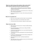
... is no good. (See checking solenoid sensor alignment.) Wiper will not operate at all • Blown fuse on power supply circuit board. (Refer to Instruction Manual) • Wiper solenoid is defective. (See checking the wiper solenoid) • Circuit board is bad. (See checking the voltage to the wiper solenoid) Wiper only...
... is no good. (See checking solenoid sensor alignment.) Wiper will not operate at all • Blown fuse on power supply circuit board. (Refer to Instruction Manual) • Wiper solenoid is defective. (See checking the wiper solenoid) • Circuit board is bad. (See checking the voltage to the wiper solenoid) Wiper only...

Wiper Problems and Solutions - English
Page 5
..., 9 or 12, and lower presser foot. If adjustment is required, loosen the two screws on the wiper and move it until the spacing is correct. Manually lower the wiper down on the screw that go to the two pins of the return spring mounts to make to inspect the thread presser...
..., 9 or 12, and lower presser foot. If adjustment is required, loosen the two screws on the wiper and move it until the spacing is correct. Manually lower the wiper down on the screw that go to the two pins of the return spring mounts to make to inspect the thread presser...
Motor Locks - English
Page 2
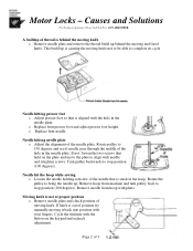
... needle up is causing the moving knife not to be able to 150 degrees and see if needle goes through the middle of position try manually moving and fixed knife. Moving knife is behind the moving knife o Remove needle plate and remove the thread build up behind the moving it back...
... needle up is causing the moving knife not to be able to 150 degrees and see if needle goes through the middle of position try manually moving and fixed knife. Moving knife is behind the moving knife o Remove needle plate and remove the thread build up behind the moving it back...
Motor Locks - English
Page 3
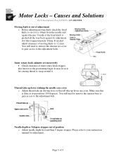
... adjust clearance of 3 Thread take up lever striking the needle case cover o Adjust thread take up levers are cover to gain access to your instruction manual for adjustment. Usually if the fixed knife is approximately 10mm. It may be in to far causing thread to the adjustment bolt. Please refer to...
... adjust clearance of 3 Thread take up lever striking the needle case cover o Adjust thread take up levers are cover to gain access to your instruction manual for adjustment. Usually if the fixed knife is approximately 10mm. It may be in to far causing thread to the adjustment bolt. Please refer to...
Changing Needle Bar Cushions - English
Page 2
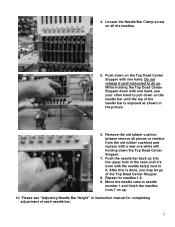
... old rubber cushion) and replace with one hand. Move the needle case to do so. 4. Push down on up into the upper hole in instruction manual for needles 1-6. 9.
... old rubber cushion) and replace with one hand. Move the needle case to do so. 4. Push down on up into the upper hole in instruction manual for needles 1-6. 9.

Maintenance Schedule - English
Page 5
Manually color change the machine to needle 1 by removing the 3 screws. 5/24/05 5 Wipe a little grease on 7. BES-940,941,1240,1241 960,961,962,963,1260,1261,1262,1263 For Technical Assistance Please Call Toll Fre e 1-877-4BROTHER Email: tsupport@brother.com Website: http://www.brother-usa.com/industembroidery/tech_down.aspx Monthly ...the knob underneath the color change box. Remove the arm cover on 12 needle machines thread take up cam. Do this for all the heads. Manually color change the machine to needle 9 on the by removing the 2 screws. Reinstall arm covers if supplied.
Manually color change the machine to needle 1 by removing the 3 screws. 5/24/05 5 Wipe a little grease on 7. BES-940,941,1240,1241 960,961,962,963,1260,1261,1262,1263 For Technical Assistance Please Call Toll Fre e 1-877-4BROTHER Email: tsupport@brother.com Website: http://www.brother-usa.com/industembroidery/tech_down.aspx Monthly ...the knob underneath the color change box. Remove the arm cover on 12 needle machines thread take up cam. Do this for all the heads. Manually color change the machine to needle 9 on the by removing the 2 screws. Reinstall arm covers if supplied.

Maintenance Schedule - English
Page 6
... the shaft clamp of the presser foot to the needle plate and make sure that the presser foot goes up and down smoothly. Manually color change to the back of the heads. 10. Before final tightening of the screws, please check the alignment of the presser foot...940,941,1240,1241 960,961,962,963,1260,1261,1262,1263 For Technical Assistance Please Call Toll Fre e 1-877-4BROTHER Email: tsupport@brother.com Website: http://www.brother-usa.com/industembroidery/tech_down.aspx Monthly Maintenance Greasing Cam grooves continued 9. Hook the spring to needle 5 if it is a 9 needle machine...
... the shaft clamp of the presser foot to the needle plate and make sure that the presser foot goes up and down smoothly. Manually color change to the back of the heads. 10. Before final tightening of the screws, please check the alignment of the presser foot...940,941,1240,1241 960,961,962,963,1260,1261,1262,1263 For Technical Assistance Please Call Toll Fre e 1-877-4BROTHER Email: tsupport@brother.com Website: http://www.brother-usa.com/industembroidery/tech_down.aspx Monthly Maintenance Greasing Cam grooves continued 9. Hook the spring to needle 5 if it is a 9 needle machine...

Maintenance Schedule - English
Page 9
Remove the color change assembly cover by rotating the knob underneath the color change box. 5/24/05 9 Manually color change screws and loosening the 2 lower ones. layed down on 12 needle machines by removing the two top screws and loosening the 2 bottom screws. 8. ... models. BES-940,941,1240,1241 960,961,962,963,1260,1261,1262,1263 For Technical Assistance Please Call Toll Fre e 1-877-4BROTHER Email: tsupport@brother.com Website: http://www.brother-usa.com/industembroidery/tech_down.aspx 6 Month Maintenance Greasing Heads continued 5.
Remove the color change assembly cover by rotating the knob underneath the color change box. 5/24/05 9 Manually color change screws and loosening the 2 lower ones. layed down on 12 needle machines by removing the two top screws and loosening the 2 bottom screws. 8. ... models. BES-940,941,1240,1241 960,961,962,963,1260,1261,1262,1263 For Technical Assistance Please Call Toll Fre e 1-877-4BROTHER Email: tsupport@brother.com Website: http://www.brother-usa.com/industembroidery/tech_down.aspx 6 Month Maintenance Greasing Heads continued 5.

Maintenance Schedule - English
Page 14
After placing the heads on . 2. Cleaning 1. Clean the inside of the sewing arm covers by manually color changing to another needle. Replace sewing arm covers when done. 5/24/05 14 Remove all of the sewing arm and hook module cooling fan ... air. 3. BES-940,941,1240,1241 960,961,962,963,1260,1261,1262,1263 For Technical Assistance Please Call Toll Fre e 1-877-4BROTHER Email: tsupport@brother.com Website: http://www.brother-usa.com/industembroidery/tech_down.aspx 6 Month Maintenance Greasing Heads continued 25. Reassemble machine in reverse order.
After placing the heads on . 2. Cleaning 1. Clean the inside of the sewing arm covers by manually color changing to another needle. Replace sewing arm covers when done. 5/24/05 14 Remove all of the sewing arm and hook module cooling fan ... air. 3. BES-940,941,1240,1241 960,961,962,963,1260,1261,1262,1263 For Technical Assistance Please Call Toll Fre e 1-877-4BROTHER Email: tsupport@brother.com Website: http://www.brother-usa.com/industembroidery/tech_down.aspx 6 Month Maintenance Greasing Heads continued 25. Reassemble machine in reverse order.

Tubular to Cap - English
Page 1
... driver over limit error occurs after turning the machine back on the pantograph. If a over the locator pins (C) and secure with the cap needle plates. 4)Manually lower all the presser feet using the lever to the right of each head. 5) Turn the pulley in the direction of the arrow to 200...
... driver over limit error occurs after turning the machine back on the pantograph. If a over the locator pins (C) and secure with the cap needle plates. 4)Manually lower all the presser feet using the lever to the right of each head. 5) Turn the pulley in the direction of the arrow to 200...

Cap to Tubular - English
Page 1
... for safekeeping. 5) Move the needle case to needle #1 using the needle select buttons . 6) Remove the cap needle plates (A) and replace with the flat needle plates. 7) Manually lower all presser feet by using the clasps and secure to the pantograph. Stand Alone - Use the flat/cap switch on . This can be made...
... for safekeeping. 5) Move the needle case to needle #1 using the needle select buttons . 6) Remove the cap needle plates (A) and replace with the flat needle plates. 7) Manually lower all presser feet by using the clasps and secure to the pantograph. Stand Alone - Use the flat/cap switch on . This can be made...

Parts Manual - English
Page 87
...-1 64-2 539821000 547263001 547227000 593960041 6 - VV )( -f z.. CORD CLAMP, 19P7 IF HARNESS SET, 20M IF HARNESS ASSY, 20M INSTRUCTION MANUAL, CABLE 155-960-515 80 R2 . HARNESS ASSY, H-SWITCH _ -- 33 S43461000 1 IP\ -47/ :.=, 10M IF HARNESS ASSY, ... 4xici 39 504557000 1 i> 9 -(PLTIM 40 539821000 14 m - g IV.1* (BES-960BC, 1260BC) / Power supply equipment mechanism (BES-960BC, 12608C) / Stromversorgung (BES-960BC, 1260BC) / Mecanisme de l'equipment en alimentation electrique (BES-960BC, 1260BC) / Mecanismo del equipo de alimentation de corriente (BES-9608C, 1260BC) REF.NO....
...-1 64-2 539821000 547263001 547227000 593960041 6 - VV )( -f z.. CORD CLAMP, 19P7 IF HARNESS SET, 20M IF HARNESS ASSY, 20M INSTRUCTION MANUAL, CABLE 155-960-515 80 R2 . HARNESS ASSY, H-SWITCH _ -- 33 S43461000 1 IP\ -47/ :.=, 10M IF HARNESS ASSY, ... 4xici 39 504557000 1 i> 9 -(PLTIM 40 539821000 14 m - g IV.1* (BES-960BC, 1260BC) / Power supply equipment mechanism (BES-960BC, 12608C) / Stromversorgung (BES-960BC, 1260BC) / Mecanisme de l'equipment en alimentation electrique (BES-960BC, 1260BC) / Mecanismo del equipo de alimentation de corriente (BES-9608C, 1260BC) REF.NO....
Instruction Manual - English
Page 1
...Embroidery Data Explains how to use the Embroidery Data Editor. Chapter 7 Operation of embroidering processes. Configuration of this manual This manual consists of the following chapters: Chapter 1 An Introduction of Embroidery Machine Provides information on machine operation during embroidering.... Embroidery Data Explains how to use the Embroidery Data Explorer. Chapter 6 Embroidering Explains how to use the Machine Controller. BES-960BC (9 needles) - BES-1260BC (12 needles) Explanation for individual model is BES-1260BC. Chapter 8 Creating Production Report Explains...
...Embroidery Data Explains how to use the Embroidery Data Editor. Chapter 7 Operation of embroidering processes. Configuration of this manual This manual consists of the following chapters: Chapter 1 An Introduction of Embroidery Machine Provides information on machine operation during embroidering.... Embroidery Data Explains how to use the Embroidery Data Explorer. Chapter 6 Embroidering Explains how to use the Machine Controller. BES-960BC (9 needles) - BES-1260BC (12 needles) Explanation for individual model is BES-1260BC. Chapter 8 Creating Production Report Explains...

Instruction Manual - English
Page 3
...connecting 4 sets) ..... 40 2-8. Preparation for Embroidering 64 Run the Software 65 Turn on the Machine Power 65 8 BES-960BC • BES-1260BC Replacing and Selecting Needle 48 3-4. Necessary Systems 17 2-2. Transportation of Machine Components 26 2. Connection of... Machine 30 2-3. Upper Threading 44 3-2. Installation of Power Supply 42 2-9. Contents SAFTY INSTRUCTIONS 1 Procedure of Reading This Manual 6 Contents ...8 Chapter 1 An Introduction of Software 43 3. Notes on Tension Plate 62 Flowchart of Preparation for Embroidering 44 3-1....
...connecting 4 sets) ..... 40 2-8. Preparation for Embroidering 64 Run the Software 65 Turn on the Machine Power 65 8 BES-960BC • BES-1260BC Replacing and Selecting Needle 48 3-4. Necessary Systems 17 2-2. Transportation of Machine Components 26 2. Connection of... Machine 30 2-3. Upper Threading 44 3-2. Installation of Power Supply 42 2-9. Contents SAFTY INSTRUCTIONS 1 Procedure of Reading This Manual 6 Contents ...8 Chapter 1 An Introduction of Software 43 3. Notes on Tension Plate 62 Flowchart of Preparation for Embroidering 44 3-1....
Instruction Manual - English
Page 107
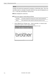
s Mask is a rectangle, the pattern within the hoop may be displayed as follows: Automatic Manual The system measures the image size to specify the mask. 112 BES-960BC • BES-1260BC Select automatic or manual mode. In this mode, specify the mask area using the mouse. 1. Select [Mask] from Change menu. If [Automatic] is...
s Mask is a rectangle, the pattern within the hoop may be displayed as follows: Automatic Manual The system measures the image size to specify the mask. 112 BES-960BC • BES-1260BC Select automatic or manual mode. In this mode, specify the mask area using the mouse. 1. Select [Mask] from Change menu. If [Automatic] is...
Instruction Manual - English
Page 174
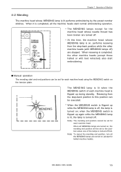
... mending end position will be set to this time, the machine head, whose MENDING lamp is lit performs embroidering by the preset number stitches. s Manual operation The mending start and end positions can be executed. * When the MENDING switch is flipped up while the MENDING lamp is off, the lamp... each machine head. The MENDING lamp is lit when the MENDING switch of each machine head using the MENDING switch on the tension plate. BES-960BC • BES-1260BC 179 Chapter 7 Operation of Machine 4-2 Mending The machine head whose MENDING lamp is on, performs resewing from the step-back ...
... mending end position will be set to this time, the machine head, whose MENDING lamp is lit performs embroidering by the preset number stitches. s Manual operation The mending start and end positions can be executed. * When the MENDING switch is flipped up while the MENDING lamp is off, the lamp... each machine head. The MENDING lamp is lit when the MENDING switch of each machine head using the MENDING switch on the tension plate. BES-960BC • BES-1260BC 179 Chapter 7 Operation of Machine 4-2 Mending The machine head whose MENDING lamp is on, performs resewing from the step-back ...
Instruction Manual - English
Page 216
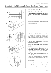
... r until the clearance between the needle and the rotary shaft to 0.3 ~ 0.5 mm at the left side of Clearance Between Needle and Rotary Hook 1. BES-960BC • BES-1260BC 221 The illustration at the needle bar No. 9 o (No. 12 needle for BES-1260BC) and the rotary hook's point becomes within...5. Note) If the clearance between the needle and the rotary hook's point to 0.3 ~ 0.5 mm. Chapter 10 Standard Adjustment 3. Turn the rotary hook manually so that the needle bar height is not within the range of the bed y. 7. For BES-1260BC, the No. 12 needle becomes 9. Remove two flat...
... r until the clearance between the needle and the rotary shaft to 0.3 ~ 0.5 mm at the left side of Clearance Between Needle and Rotary Hook 1. BES-960BC • BES-1260BC 221 The illustration at the needle bar No. 9 o (No. 12 needle for BES-1260BC) and the rotary hook's point becomes within...5. Note) If the clearance between the needle and the rotary hook's point to 0.3 ~ 0.5 mm. Chapter 10 Standard Adjustment 3. Turn the rotary hook manually so that the needle bar height is not within the range of the bed y. 7. For BES-1260BC, the No. 12 needle becomes 9. Remove two flat...
Instruction Manual - English
Page 217
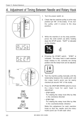
...set timing position and the rotary hook can fit with each machine head so that the machine pulley is indicated on . 2. Turn the machine pulley manually until it comes to the stop position, press the JOG switch (E) while holding down the STOP switch. Press the STEP BACK/FWD switch to move... the rotary hook for each other. 222 BES-960BC • BES-1260BC Chapter 10 Standard Adjustment 4. Adjustment of the scale). 6. "AJST" is at the stop position (at around 140° of Timing Between...
...set timing position and the rotary hook can fit with each machine head so that the machine pulley is indicated on . 2. Turn the machine pulley manually until it comes to the stop position, press the JOG switch (E) while holding down the STOP switch. Press the STEP BACK/FWD switch to move... the rotary hook for each other. 222 BES-960BC • BES-1260BC Chapter 10 Standard Adjustment 4. Adjustment of the scale). 6. "AJST" is at the stop position (at around 140° of Timing Between...

Instruction Manual - English
Page 228
... to interference with a hand. 3.Leave thread of about 60 ~ 70 mm from the needle hole when starting embroidering, hook the thread end on ? BES-960BC • BES-1260BC 233 sStitches cannot be rotated forcibly by manual operation. 2.Check that the machine pulley is set screw of the needle and rotary hook correct?
... to interference with a hand. 3.Leave thread of about 60 ~ 70 mm from the needle hole when starting embroidering, hook the thread end on ? BES-960BC • BES-1260BC 233 sStitches cannot be rotated forcibly by manual operation. 2.Check that the machine pulley is set screw of the needle and rotary hook correct?


