
Maintenance Schedule - English
Page 1
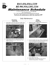
... 50 degrees is not over 2 inches long. Open the bobbin case cover. Compressed air may also be used. Make sure bobbin thread is at the top. 2. Place a small drop of the arrow or forward to stop position, 100 degrees. 9/1/05 1 Close bobbin case cover. 4. Use brush to rotary hook. Insert bobbin case in to remove lint build up in the direction of oil on the raceway as indicated by the arrow...
... 50 degrees is not over 2 inches long. Open the bobbin case cover. Compressed air may also be used. Make sure bobbin thread is at the top. 2. Place a small drop of the arrow or forward to stop position, 100 degrees. 9/1/05 1 Close bobbin case cover. 4. Use brush to rotary hook. Insert bobbin case in to remove lint build up in the direction of oil on the raceway as indicated by the arrow...
Maintenance Schedule - English
Page 2
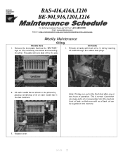
... drop of oil on it by removing one or two hours of operation. Replace cover. 9/1/05 2 The plate will now slide off to the machine. 3. Note: Oil may run out in the two locations. A part that can be supplied to the side. BAS-416,416A,1210 BE-901,916,1201,1216 For Technical Assistance Please Call Toll Fre e 1-877-4BROTHER Email: tsupport@brother...
... drop of oil on it by removing one or two hours of operation. Replace cover. 9/1/05 2 The plate will now slide off to the machine. 3. Note: Oil may run out in the two locations. A part that can be supplied to the side. BAS-416,416A,1210 BE-901,916,1201,1216 For Technical Assistance Please Call Toll Fre e 1-877-4BROTHER Email: tsupport@brother...
Maintenance Schedule - English
Page 3
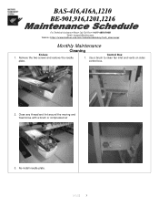
Clean any thread and lint around the moving and fixed knive with a brush or compressed air 3. Re-install needle plate. 9/1/05 3 Use a brush to clean fan inlet and vents on sides control box. 2. Remove the two screws and remove the needle plate. Control Box 1. BAS-416,416A,1210 BE-901,916,1201,1216 For Technical Assistance Please Call Toll Fre e 1-877-4BROTHER Email: tsupport@brother.com Website: http://www.brother-usa.com/industembroidery/tech_down.aspx Monthly Maintenance Cleaning Knives 1.
Clean any thread and lint around the moving and fixed knive with a brush or compressed air 3. Re-install needle plate. 9/1/05 3 Use a brush to clean fan inlet and vents on sides control box. 2. Remove the two screws and remove the needle plate. Control Box 1. BAS-416,416A,1210 BE-901,916,1201,1216 For Technical Assistance Please Call Toll Fre e 1-877-4BROTHER Email: tsupport@brother.com Website: http://www.brother-usa.com/industembroidery/tech_down.aspx Monthly Maintenance Cleaning Knives 1.
Maintenance Schedule - English
Page 4
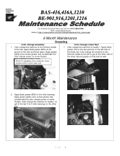
... on that side as well. BAS-416,416A,1210 BE-901,916,1201,1216 For Technical As sistance Please Call Toll Free 1-877-4BROTHER Email: tsupport@brother.com Website: http://www.brother-usa.com/industembroidery/tech_down.aspx 6 Month Maintenance Greasing Color Change Assembly Color Change Linear Rail 1. Color change sensor on some models. Knob for changing colors manually. Apply white to the roller...
... on that side as well. BAS-416,416A,1210 BE-901,916,1201,1216 For Technical As sistance Please Call Toll Free 1-877-4BROTHER Email: tsupport@brother.com Website: http://www.brother-usa.com/industembroidery/tech_down.aspx 6 Month Maintenance Greasing Color Change Assembly Color Change Linear Rail 1. Color change sensor on some models. Knob for changing colors manually. Apply white to the roller...
Maintenance Schedule - English
Page 5
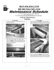
... right side of the linear rail its entire length. This will 1. Apply see the X linear rail. BAS-416,416A,1210 BE-901,916,1201,1216 For Technical Assistance Please Call Toll Fre e 1-877-4BROTHER Email: tsupport@brother.com Website: http://www.brother-usa.com/industembroidery/tech_down.aspx 6 Month Maintenance Greasing X Linear Rail Y Linear Rails 1. Push the...
... right side of the linear rail its entire length. This will 1. Apply see the X linear rail. BAS-416,416A,1210 BE-901,916,1201,1216 For Technical Assistance Please Call Toll Fre e 1-877-4BROTHER Email: tsupport@brother.com Website: http://www.brother-usa.com/industembroidery/tech_down.aspx 6 Month Maintenance Greasing X Linear Rail Y Linear Rails 1. Push the...
Maintenance Schedule - English
Page 6
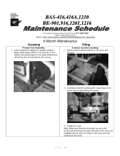
...,1201,1216 For Technical Assistance Please Call Toll Fre e 1-877-4BROTHER Email: tsupport@brother.com Website: http://www.brother-usa.com/industembroidery/tech_down.aspx 6 Month Maintenance Greasing Oiling Presser Foot Assembly 1. Apply black grease (BR2) to the grooves of oil to needle number 1. Install the cover. Color change the machine to the slot as indicated by the cover. 9/1/05 6 Lubricate eccentric bushing with a few drops of the presser foot guide plate...
...,1201,1216 For Technical Assistance Please Call Toll Fre e 1-877-4BROTHER Email: tsupport@brother.com Website: http://www.brother-usa.com/industembroidery/tech_down.aspx 6 Month Maintenance Greasing Oiling Presser Foot Assembly 1. Apply black grease (BR2) to the grooves of oil to needle number 1. Install the cover. Color change the machine to the slot as indicated by the cover. 9/1/05 6 Lubricate eccentric bushing with a few drops of the presser foot guide plate...
Cap to Tubular - English
Page 1
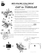
... black thumb screw (G) and slide the guide bar (F) out of the lower arm. 3) Remove the two short black thumb screws, inner ones, (E) and remove the cap driver from guide pins (C). 5) Remove the cap needle plate (A-2) and replace with lever. 11) Place the TUBULAR arm attachment (A) onto the machine over the positioning pins (C). 12) Attach using the longer Philips screws that have both a flat and spring washer. Swing the L shape bracket (H) down. BES-916,901,1216,1201AC...
... black thumb screw (G) and slide the guide bar (F) out of the lower arm. 3) Remove the two short black thumb screws, inner ones, (E) and remove the cap driver from guide pins (C). 5) Remove the cap needle plate (A-2) and replace with lever. 11) Place the TUBULAR arm attachment (A) onto the machine over the positioning pins (C). 12) Attach using the longer Philips screws that have both a flat and spring washer. Swing the L shape bracket (H) down. BES-916,901,1216,1201AC...
Head Board Replacement - English
Page 1
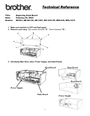
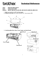
Technical Reference Title: Date: Models: Replacing Head Board February 25, 2009 BE-901, BE-901-PC, BE-1201, BE-1201-PC, BES-916, BES-1216 1. Identifying Main Bord. (Also: Power Supply, and Head Board) Head Board Main Board Power Supply Head Board Main Board Power Supply 1 Make sure machine is OFF and Unplugged. 2. Remove cover assy. (Six screws removed "A", Three loosened "B") A B A A A A A 3.
Technical Reference Title: Date: Models: Replacing Head Board February 25, 2009 BE-901, BE-901-PC, BE-1201, BE-1201-PC, BES-916, BES-1216 1. Identifying Main Bord. (Also: Power Supply, and Head Board) Head Board Main Board Power Supply Head Board Main Board Power Supply 1 Make sure machine is OFF and Unplugged. 2. Remove cover assy. (Six screws removed "A", Three loosened "B") A B A A A A A 3.

Head Board Replacement - English
Page 3
Once you remove the old board you are ready for operation. 3 Please follow reverse instructions on the board is installed and all plugged in you are ready to model of machine. (For version up-grading machine please follow version upgrade procedure.) 9. A. After board is set to 1. 8. B. 7. Make sure that the rotary switch on removal. Installing board - After board is installed, machine is version up-graded and restarted you will need to perform a version up-grade in accordance to install the new one.
Once you remove the old board you are ready for operation. 3 Please follow reverse instructions on the board is installed and all plugged in you are ready to model of machine. (For version up-grading machine please follow version upgrade procedure.) 9. A. After board is set to 1. 8. B. 7. Make sure that the rotary switch on removal. Installing board - After board is installed, machine is version up-graded and restarted you will need to perform a version up-grade in accordance to install the new one.
Main Board Replacement - English
Page 1
Remove cover assy. (Six screws removed "A", Three loosened "B") A B A A A A A 3. Identifying Main Bord. (Also: Power Supply, and Head Board) Head Board Main Board Power Supply Head Board Main Board Power Supply 1 Make sure machine is OFF and Unplugged. 2. Technical Reference Title: Date: Models: Replacing Main Board February 25, 2009 BE-901, BE-901-PC, BE-1201, BE-1201-PC, BES-916, BES-1216 1.
Remove cover assy. (Six screws removed "A", Three loosened "B") A B A A A A A 3. Identifying Main Bord. (Also: Power Supply, and Head Board) Head Board Main Board Power Supply Head Board Main Board Power Supply 1 Make sure machine is OFF and Unplugged. 2. Technical Reference Title: Date: Models: Replacing Main Board February 25, 2009 BE-901, BE-901-PC, BE-1201, BE-1201-PC, BES-916, BES-1216 1.

Main Board Replacement - English
Page 2
Unplug all wire connector harnesses. In order to unlock you will need to squeese locks and lightly pull-up on board to remove board. Board is held inplace by plastic clip locks. Note following connecters are not used or have jumper: P5 & P25-have a jumper, P1, P3, P4, P6, P8, P10, P11 and P13-Not used: marked with asterisk *. * *** * * * * * * 5. Unplugging all connectores to release. 2 However, keep in mind that connectors only go in one spot and can not be confused. 6. 4.
Unplug all wire connector harnesses. In order to unlock you will need to squeese locks and lightly pull-up on board to remove board. Board is held inplace by plastic clip locks. Note following connecters are not used or have jumper: P5 & P25-have a jumper, P1, P3, P4, P6, P8, P10, P11 and P13-Not used: marked with asterisk *. * *** * * * * * * 5. Unplugging all connectores to release. 2 However, keep in mind that connectors only go in one spot and can not be confused. 6. 4.
Main Board Replacement - English
Page 4
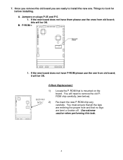
... OK. Re-insert the new P-ROM chip very carefully. Use extreme caution when performing this will need to look for before installing. Things to remove the old PROM chip carefully (see below). P-ROM = 1. Jumpers on the board. this task. 4 You will be OK. You must ensure that all the legs are entering the proper hole and that...
... OK. Re-insert the new P-ROM chip very carefully. Use extreme caution when performing this will need to look for before installing. Things to remove the old PROM chip carefully (see below). P-ROM = 1. Jumpers on the board. this task. 4 You will be OK. You must ensure that all the legs are entering the proper hole and that...
Main Board Replacement - English
Page 5
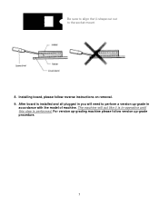
After board is performed. The machine will act like it is in-operative until this step is installed and all plugged in accordance with the model of machine. For version up-grading machine please follow reverse instructions on removal. 9. Be sure to align the U-shape cut out to perform a version up-grade in you will need to the socket mount. 8. Installing board, please follow version up-grade procedure. 5
After board is performed. The machine will act like it is in-operative until this step is installed and all plugged in accordance with the model of machine. For version up-grading machine please follow reverse instructions on removal. 9. Be sure to align the U-shape cut out to perform a version up-grade in you will need to the socket mount. 8. Installing board, please follow version up-grade procedure. 5

Power Supply Replacement - English
Page 1
Technical Reference Title: Date: Models: Replacing Power Supply Board February 25, 2009 BE-901, BE-901-PC, BE-1201, BE-1201-PC, BES-916, BES-1216 1. Remove cover assy. (Six screws removed "A", Three loosened "B") A B A A A A A 3. Identifying Main Bord. (Also: Power Supply, and Head Board) Head Board Main Board Power Supply Head Board Main Board Power Supply 1 Make sure machine is OFF and Unplugged. 2.
Technical Reference Title: Date: Models: Replacing Power Supply Board February 25, 2009 BE-901, BE-901-PC, BE-1201, BE-1201-PC, BES-916, BES-1216 1. Remove cover assy. (Six screws removed "A", Three loosened "B") A B A A A A A 3. Identifying Main Bord. (Also: Power Supply, and Head Board) Head Board Main Board Power Supply Head Board Main Board Power Supply 1 Make sure machine is OFF and Unplugged. 2.
Power Supply Replacement - English
Page 3
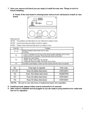
A. Installing board, please follow reverse instructions of removal. 9. Things to install on for before installing. Once you remove old board you are ready to plug machine into outlet and turn on new board. 8. Fuses: If the new board is installed and all plugged in you are ready to install the new one. 7. After board is missing fuses remove from old board to look for operation. 3
A. Installing board, please follow reverse instructions of removal. 9. Things to install on for before installing. Once you remove old board you are ready to plug machine into outlet and turn on new board. 8. Fuses: If the new board is installed and all plugged in you are ready to install the new one. 7. After board is missing fuses remove from old board to look for operation. 3
Color Change Potentiometer Replacement - English
Page 1
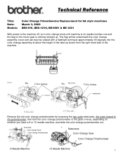
... Color Change Potentiometer 9 Needle Machine 12 Needle Machine 1 Technical Reference Title: Date: Models: Color Change Potentiometer Replacement for SA style machines March 3, 2009 BES-916, BES-1216, BE-0901 & BE-1201 With power to the gear or knob, depending on the motor gear is sticking straight up levers from the right hand side of the take-up . The flag will be underneath the color change assembly cover...
... Color Change Potentiometer 9 Needle Machine 12 Needle Machine 1 Technical Reference Title: Date: Models: Color Change Potentiometer Replacement for SA style machines March 3, 2009 BES-916, BES-1216, BE-0901 & BE-1201 With power to the gear or knob, depending on the motor gear is sticking straight up levers from the right hand side of the take-up . The flag will be underneath the color change assembly cover...
Color Change Potentiometer Replacement - English
Page 2
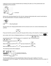
...Remove the mounting bracket from the old color change potentiometer with the or jog key and press the key. It will then ask you to confirm going into test mode. Select the icon with a wrench and install on the new potentiometer in the same orientation as the old one. Mounting Bracket Plug the new color change... potentiometer by following screen will also start beep continuously when the number 19 is displayed asking you for a password... 2 The machine will be ...
...Remove the mounting bracket from the old color change potentiometer with the or jog key and press the key. It will then ask you to confirm going into test mode. Select the icon with a wrench and install on the new potentiometer in the same orientation as the old one. Mounting Bracket Plug the new color change... potentiometer by following screen will also start beep continuously when the number 19 is displayed asking you for a password... 2 The machine will be ...
Color Change Potentiometer Replacement - English
Page 3
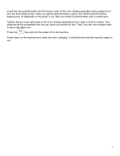
...the color change knob to get the potentiometer in place. One setscrew will be accessible from the top, which you get to the other one. It should still be fine and the machine ready to turn the power off to hold it comes back. Power back on the panel. Insert the new potentiometer ...into the knob or gear of the color change assembly being careful not to run. 3 Then, turn shaft of potentiometer until ...
...the color change knob to get the potentiometer in place. One setscrew will be accessible from the top, which you get to the other one. It should still be fine and the machine ready to turn the power off to hold it comes back. Power back on the panel. Insert the new potentiometer ...into the knob or gear of the color change assembly being careful not to run. 3 Then, turn shaft of potentiometer until ...
Changing Needle Bar Cushions - English
Page 1
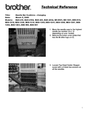
changing Date: March 5, 2009 Models: BAS-416, BAS-416A, BAS-423, BAS-423A, BE-0901, BE-1201, BES-916, BES-1216, BES-1230, BES-1210, BES-1240, BES-1241, BES-1260, BES-1261, BES- 1262, BES-1263, BES-960, BES-961 1. Technical Reference Title: Needle Bar Cushions - Remove the lower cover (plate that has the Brother logo on your model). 2. Move the needle case to the highest needle bar number (9 or 12 depending on it). 3. Loosen Top Dead Center Stopper screw with a 2.5mm hex wrench on all the needles. 1
changing Date: March 5, 2009 Models: BAS-416, BAS-416A, BAS-423, BAS-423A, BE-0901, BE-1201, BES-916, BES-1216, BES-1230, BES-1210, BES-1240, BES-1241, BES-1260, BES-1261, BES- 1262, BES-1263, BES-960, BES-961 1. Technical Reference Title: Needle Bar Cushions - Remove the lower cover (plate that has the Brother logo on your model). 2. Move the needle case to the highest needle bar number (9 or 12 depending on it). 3. Loosen Top Dead Center Stopper screw with a 2.5mm hex wrench on all the needles. 1
Changing Needle Bar Cushions - English
Page 2
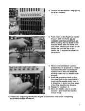
...remove all the needles. 5. Loosen the Needle Bar Clamp screw on all pieces or residue from 7 on the needle bar until the top of the needle bar is done, you may let go of each needle bar. 2 While holding down the Top Dead Center Stopper. 7. Move the needle case to pull down with one hand, use your other hand to needle number 1 and finish the needles...into the upper hole in instruction manual for needles 1-6. 9. Do not release it until it . Please see "Adjusting Needle Bar Height" in the case until instructed to it 's even with a new one hand. Push the needle bar back up ...
...remove all the needles. 5. Loosen the Needle Bar Clamp screw on all pieces or residue from 7 on the needle bar until the top of the needle bar is done, you may let go of each needle bar. 2 While holding down the Top Dead Center Stopper. 7. Move the needle case to pull down with one hand, use your other hand to needle number 1 and finish the needles...into the upper hole in instruction manual for needles 1-6. 9. Do not release it until it . Please see "Adjusting Needle Bar Height" in the case until instructed to it 's even with a new one hand. Push the needle bar back up ...


