
Assembly Manual
Page 1
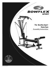
The Bowflex Sport® Home Gym Assembly Instructions 001-6961 Rev B (06-19-06)
The Bowflex Sport® Home Gym Assembly Instructions 001-6961 Rev B (06-19-06)

Assembly Manual
Page 2
Safety Precautions Get to Know Your Machine Basic Assembly Principles Parts List Hardware List Accessory List Hardware Guide Tools You Will Need Assembly Guide Important Contact Numbers Table of Contents 1 2 3 3 3 3 4 4 5 20
Safety Precautions Get to Know Your Machine Basic Assembly Principles Parts List Hardware List Accessory List Hardware Guide Tools You Will Need Assembly Guide Important Contact Numbers Table of Contents 1 2 3 3 3 3 4 4 5 20
Assembly Manual
Page 4
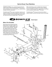
... to Know Your Machine CONGRATULATIONS on a hard, level surface. With the Bowflex Sport ® home gym, you have everything you 're just about to prove it , as the Bowflex Sport® home gym does not go T through doors easily once fully assembled. The Bowflex Sport ® home gym's exceptional resistance and quality is on your commitment to...
... to Know Your Machine CONGRATULATIONS on a hard, level surface. With the Bowflex Sport ® home gym, you have everything you 're just about to prove it , as the Bowflex Sport® home gym does not go T through doors easily once fully assembled. The Bowflex Sport ® home gym's exceptional resistance and quality is on your commitment to...
Assembly Manual
Page 5
...; home gym, turn bolts or nuts toward the right to tighten and left to starting assembly for all bolts and nuts on your assembly of the Bowflex Sport® home gym quick and easy. Qty. R 1 S 1 T 2 U 1 V 2 W 2 Y 2 Z 2 AA 1 BB 2 Description SQUAT BAR BENT LAT BAR HAND GRIPS ... HOOKS (attached) LEG CABLE SQUAT CABLES W/ 2 SNAP HOOKS (attached) NOTE: LEAVE ALL CABLES WRAPPED AND BAGGED UNTIL YOUR BOWFLEX SPORT® HOME GYM IS FULLY ASSEMBLED. *Specifications subject to help guide the bolt through the holes. 4. Or you need for each process and save yourself extra ...
...; home gym, turn bolts or nuts toward the right to tighten and left to starting assembly for all bolts and nuts on your assembly of the Bowflex Sport® home gym quick and easy. Qty. R 1 S 1 T 2 U 1 V 2 W 2 Y 2 Z 2 AA 1 BB 2 Description SQUAT BAR BENT LAT BAR HAND GRIPS ... HOOKS (attached) LEG CABLE SQUAT CABLES W/ 2 SNAP HOOKS (attached) NOTE: LEAVE ALL CABLES WRAPPED AND BAGGED UNTIL YOUR BOWFLEX SPORT® HOME GYM IS FULLY ASSEMBLED. *Specifications subject to help guide the bolt through the holes. 4. Or you need for each process and save yourself extra ...
Assembly Manual
Page 6
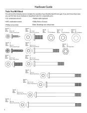
....: Descr: J 2 3/8" X 4 1/4" Button Head Screw Item #: Qty.: Descr: K 4 3/8" X 5" Button Head Screw 4 Hardware Guide Tools You Will Need You will need the following tools to complete the assembly of your Bowflex Sport® home gym.
....: Descr: J 2 3/8" X 4 1/4" Button Head Screw Item #: Qty.: Descr: K 4 3/8" X 5" Button Head Screw 4 Hardware Guide Tools You Will Need You will need the following tools to complete the assembly of your Bowflex Sport® home gym.

Assembly Manual
Page 7
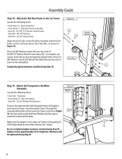
... Base Platform first, then tip the Base Platform back to the Base Platform Locate the following items: • From Step 1 - Base Platform/Lower Lat Tower Assembly • Item #3 - Base Left Leg - Base Platform • Item #H - (4) 3/8" X 3" Button Head Screws • Item #N - (8) 3/8" Washers &#...8226; Item #E - (4) 3/8" X 3/4" Button Head Screws • Item #N - (4) 3/8" Washers With the Base Platform/Lower Lat Tower Assembly (from each Leg with the holes in Figure 2. Completely tighten hardware installed during Step 2. Line up the two bolt holes on each Base Leg ...
... Base Platform first, then tip the Base Platform back to the Base Platform Locate the following items: • From Step 1 - Base Platform/Lower Lat Tower Assembly • Item #3 - Base Left Leg - Base Platform • Item #H - (4) 3/8" X 3" Button Head Screws • Item #N - (8) 3/8" Washers &#...8226; Item #E - (4) 3/8" X 3/4" Button Head Screws • Item #N - (4) 3/8" Washers With the Base Platform/Lower Lat Tower Assembly (from each Leg with the holes in Figure 2. Completely tighten hardware installed during Step 2. Line up the two bolt holes on each Base Leg ...

Assembly Manual
Page 8
... 3/8" X 3 1/4" Button Head Screws (Item #I) - one cover per bolt, that attach the Pulleys to the Main Assembly Locate the following items: • From Step 2 - Completely tighten hardware installed during Step 3. Figure 3a O Base Platform/Lower Lat Tower Assembly N I - (2) 3/8" X 3 1/4" Button Head Screws • Item #N - (4) 3/8" Washers • Item ...#O - (2) 3/8" Nylock Nuts • Item #Q - (4) Bolt Covers With the Base Frame/Lower Lat Tower (Main) Assembly (from Step 2) on the floor, carefully lift up the bolt holes in the brackets on the Squat Platform with the bolt holes ...
... 3/8" X 3 1/4" Button Head Screws (Item #I) - one cover per bolt, that attach the Pulleys to the Main Assembly Locate the following items: • From Step 2 - Completely tighten hardware installed during Step 3. Figure 3a O Base Platform/Lower Lat Tower Assembly N I - (2) 3/8" X 3 1/4" Button Head Screws • Item #N - (4) 3/8" Washers • Item ...#O - (2) 3/8" Nylock Nuts • Item #Q - (4) Bolt Covers With the Base Frame/Lower Lat Tower (Main) Assembly (from Step 2) on the floor, carefully lift up the bolt holes in the brackets on the Squat Platform with the bolt holes ...

Assembly Manual
Page 9
... 5" Button Head Screws (Item #K) - Completely tighten hardware installed during Step 4. Figure 5 M 7 Chest Bar Brackets 6 O Base Platform/ Lower Lat Tower Assembly C 8 Cut-out Angled Edge 7 Place (2) 3/8" Washers (Item #N) over (4) 5/16" X 3/4" Button Head Screws (Item #C) - Insert the screws ...3/8" Nylock Nuts (Item #O) over each screw. Align the four holes in the brackets on the Chest Bar with Pulleys (Item #6) with Pulleys to the Main Assembly Locate the following items: • Item #7 - Do not unwrap cables! • Item #K - (2) 3/8" X 5" Button Head Screws • Item #N...
... 5" Button Head Screws (Item #K) - Completely tighten hardware installed during Step 4. Figure 5 M 7 Chest Bar Brackets 6 O Base Platform/ Lower Lat Tower Assembly C 8 Cut-out Angled Edge 7 Place (2) 3/8" Washers (Item #N) over (4) 5/16" X 3/4" Button Head Screws (Item #C) - Insert the screws ...3/8" Nylock Nuts (Item #O) over each screw. Align the four holes in the brackets on the Chest Bar with Pulleys (Item #6) with Pulleys to the Main Assembly Locate the following items: • Item #7 - Do not unwrap cables! • Item #K - (2) 3/8" X 5" Button Head Screws • Item #N...

Assembly Manual
Page 10
...holes in the Seat Rail. Completely tighten hardware installed during Step 7. Seat Rail Undo the twist ties from Step 5). Once you have attached the Seat Assembly to the Rear Leg Cross Tube Locate the following items: • From Step 5 - Insert the screws through the Seat Bracket, (see Figure 6).... not unwrap cables! • Item #11 - Place (2) 3/8" Washers (Item #N) over the end of this step. Note: See Step 22 to the Seat Assembly Locate the following items: • Item #10 - Attach the Rear Leg to the Seat Rail, reinstall the Rail Pivot Bushings that the Pull Pin on...
...holes in the Seat Rail. Completely tighten hardware installed during Step 7. Seat Rail Undo the twist ties from Step 5). Once you have attached the Seat Assembly to the Rear Leg Cross Tube Locate the following items: • From Step 5 - Insert the screws through the Seat Bracket, (see Figure 6).... not unwrap cables! • Item #11 - Place (2) 3/8" Washers (Item #N) over the end of this step. Note: See Step 22 to the Seat Assembly Locate the following items: • Item #10 - Attach the Rear Leg to the Seat Rail, reinstall the Rail Pivot Bushings that the Pull Pin on...

Assembly Manual
Page 11
... X 4 1/4" Button Head Screw • Item #N - (2) 3/8" Washers • Item #O - (1) 3/8" Nylock Nut • Item #Q - (2) Bolt Covers Undo the twist ties from Step 7) to the Seat Rail Assembly, rotate the Rear Leg forward (as shown in Figure 8b), to allow the Leg Latch to the Seat Rail Locate the following items: • From... Step 6 - Note: Tighten the nylock nut enough that the Leg Assembly can move freely. Align the holes on the End Bracket of the screw extend through the nylock nut, but do not remove the Bushings...
... X 4 1/4" Button Head Screw • Item #N - (2) 3/8" Washers • Item #O - (1) 3/8" Nylock Nut • Item #Q - (2) Bolt Covers Undo the twist ties from Step 7) to the Seat Rail Assembly, rotate the Rear Leg forward (as shown in Figure 8b), to allow the Leg Latch to the Seat Rail Locate the following items: • From... Step 6 - Note: Tighten the nylock nut enough that the Leg Assembly can move freely. Align the holes on the End Bracket of the screw extend through the nylock nut, but do not remove the Bushings...

Assembly Manual
Page 12
... the Seat Rail Knob (Item #12) into the Seat Rail Bracket, and then place (1) 3/8" Washer (Item #N) over the end of the screw to the Main Assembly Locate the following items: • From Step 4 - Seat Rail Knob • Item #J - (1) 3/8" X 4 1/4" Button Head Screw • Item #N - (2) 3/8" Washers &#...8226; Item #O - (1) 3/8" Nylock Nut • Item #Q - (1) Bolt Cover Align the holes on the Seat Rail Assembly (from Step 8) with the holes in the Rail Bracket on the Seat Rail Bracket, as shown in Figure 9, but loosely enough that the Seat Rail...
... the Seat Rail Knob (Item #12) into the Seat Rail Bracket, and then place (1) 3/8" Washer (Item #N) over the end of the screw to the Main Assembly Locate the following items: • From Step 4 - Seat Rail Knob • Item #J - (1) 3/8" X 4 1/4" Button Head Screw • Item #N - (2) 3/8" Washers &#...8226; Item #O - (1) 3/8" Nylock Nut • Item #Q - (1) Bolt Cover Align the holes on the Seat Rail Assembly (from Step 8) with the holes in the Rail Bracket on the Seat Rail Bracket, as shown in Figure 9, but loosely enough that the Seat Rail...

Assembly Manual
Page 13
...(1) Bolt Cover (Item #Q) over the end of (1) 3/8" X 2 3/4" Button Head Screw (Item #G). Place (1) 3/8" Washer (Item #N) over the Nylock Nut installed during Step 10. Main Assembly • Item #30 - Do not over the end of the Rear Leg, as shown in place while folding the Rail up (see Figure 10b). Note...: When storing the Rail Assembly, insert the Lock Out Pin (Item #30) through the aligned holes and bushings and secure by placing (1) 3/8" Washer and (1) 3/8" Nylock Nut (...
...(1) Bolt Cover (Item #Q) over the end of (1) 3/8" X 2 3/4" Button Head Screw (Item #G). Place (1) 3/8" Washer (Item #N) over the Nylock Nut installed during Step 10. Main Assembly • Item #30 - Do not over the end of the Rear Leg, as shown in place while folding the Rail up (see Figure 10b). Note...: When storing the Rail Assembly, insert the Lock Out Pin (Item #30) through the aligned holes and bushings and secure by placing (1) 3/8" Washer and (1) 3/8" Nylock Nut (...

Assembly Manual
Page 14
...12, and tighten. the Roller should rest on the Leg Extension. Place (1) 3/8" Washer (Item #N) over the end of (1) 3/8" X 2 1/2" Button Head Screw (Item #F). Main Assembly • Item #14 - Main Assembly • Item #AA - (1) Leg Cable • Item #F - (1) 3/8" X 2 1/2" Button Head Screw • Item #N - (2) 3/8" Washers • Item #O -...in Figure 11. Note: Use a Rubber Mallet to the Leg Extension Locate the following items: • From Step 11 - Assembly Guide Step 11 - There are (3) Chrome Roller Tubes on your height - Then, slide (2) Foam Rollers (Item #14) ...
...12, and tighten. the Roller should rest on the Leg Extension. Place (1) 3/8" Washer (Item #N) over the end of (1) 3/8" X 2 1/2" Button Head Screw (Item #F). Main Assembly • Item #14 - Main Assembly • Item #AA - (1) Leg Cable • Item #F - (1) 3/8" X 2 1/2" Button Head Screw • Item #N - (2) 3/8" Washers • Item #O -...in Figure 11. Note: Use a Rubber Mallet to the Leg Extension Locate the following items: • From Step 11 - Assembly Guide Step 11 - There are (3) Chrome Roller Tubes on your height - Then, slide (2) Foam Rollers (Item #14) ...

Assembly Manual
Page 15
...; Item #21 - Place (4) 5/16" Washers (Item #M) over each screw. one over (4) 5/16" X 3/4" Button Head Screws (Item #C) - Insert the screws through the aligned holes, and tighten. Assembly Guide Step 13 - Leg Extension Seat Support Tube • Item #C - (4) 5/16" X 3/4" Button Head Screws • Item #M - (4) 5/16" Washers Figure 13 21 Rail Bracket Place the... Curved Edge 13 Align the holes in the Leg Extension Seat Support Tube (Item #21) with the holes on the underside of the Seat Pad. Assemble the Leg Extension Seat Locate the following items: • Item #19 -
...; Item #21 - Place (4) 5/16" Washers (Item #M) over each screw. one over (4) 5/16" X 3/4" Button Head Screws (Item #C) - Insert the screws through the aligned holes, and tighten. Assembly Guide Step 13 - Leg Extension Seat Support Tube • Item #C - (4) 5/16" X 3/4" Button Head Screws • Item #M - (4) 5/16" Washers Figure 13 21 Rail Bracket Place the... Curved Edge 13 Align the holes in the Leg Extension Seat Support Tube (Item #21) with the holes on the underside of the Seat Pad. Assemble the Leg Extension Seat Locate the following items: • Item #19 -

Assembly Manual
Page 16
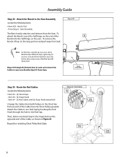
...not unwrap cables! • Item #23 - Figure 15 O N H 23 22 Lat Tower Bracket 14 To remove the Leg Extension Seat Assembly, reverse this procedure. Attach the Lat Cross Bar to the Upper Lat Tower Locate the following items: • From Step 13 - Completely ... Bracket Hooks fully engage with the holes in the bracket on the Upper Lat Tower (Item #23). Place (2) 3/8" Washers (Item #N) over each screw and tighten. Assembly Guide Step 14 - Upper Lat Tower • Item #H - (2) 3/8" X 3" Button Head Screws • Item #N - (4) 3/8" Washers • Item #O - (2) 3/8" Nylock...
...not unwrap cables! • Item #23 - Figure 15 O N H 23 22 Lat Tower Bracket 14 To remove the Leg Extension Seat Assembly, reverse this procedure. Attach the Lat Cross Bar to the Upper Lat Tower Locate the following items: • From Step 13 - Completely ... Bracket Hooks fully engage with the holes in the bracket on the Upper Lat Tower (Item #23). Place (2) 3/8" Washers (Item #N) over each screw and tighten. Assembly Guide Step 14 - Upper Lat Tower • Item #H - (2) 3/8" X 3" Button Head Screws • Item #N - (4) 3/8" Washers • Item #O - (2) 3/8" Nylock...

Assembly Manual
Page 17
...of (3) #10 X 1" Phillips Head Screws (Item #B) - Slide the Rod Box with Power Rods® (Item #25) onto one side as shown in Figure 17. Main Assembly • Item #E - (6) 3/8" X 3/4" Button Head Screw • Item #N - (6) 3/8" Washers Carefully insert the end of the Upper Lat Tower into the aligned holes,...is completely seated in the Rod Box with Power Rods® to the Lower Locate the following items: Figure 17 • Item #24 - Assembly Guide Step 16 - Attach the Upper Lat Tower to the Rod Box Frame Locate the following items: • From Step 15 - Completely ...
...of (3) #10 X 1" Phillips Head Screws (Item #B) - Slide the Rod Box with Power Rods® (Item #25) onto one side as shown in Figure 17. Main Assembly • Item #E - (6) 3/8" X 3/4" Button Head Screw • Item #N - (6) 3/8" Washers Carefully insert the end of the Upper Lat Tower into the aligned holes,...is completely seated in the Rod Box with Power Rods® to the Lower Locate the following items: Figure 17 • Item #24 - Assembly Guide Step 16 - Attach the Upper Lat Tower to the Rod Box Frame Locate the following items: • From Step 15 - Completely ...
Assembly Manual
Page 18
... A #10 Phillips Head Screws (Item #A) into the holes. Chest Bar O Completely tighten hardware installed during Step 19 tighten screws approximately 1/2 of completion. Rod Box/Frame Assembly • Item #K - (2) 3/8" X 5" Button Head Screws • Item #N - (4) 3/8" Washers • Item #O - (2) 3/8" Nylock Nuts Align the bolt...through the corresponding holes on the Lat Tower above the Chest Bar , as shown in Figure 18. Main Assembly • Item #A - (2) #10 Phillips Head Screws Figure 19 Faceplate "Stems" Position the textured side of (2) 3/8" X 5" Button Head...
... A #10 Phillips Head Screws (Item #A) into the holes. Chest Bar O Completely tighten hardware installed during Step 19 tighten screws approximately 1/2 of completion. Rod Box/Frame Assembly • Item #K - (2) 3/8" X 5" Button Head Screws • Item #N - (4) 3/8" Washers • Item #O - (2) 3/8" Nylock Nuts Align the bolt...through the corresponding holes on the Lat Tower above the Chest Bar , as shown in Figure 18. Main Assembly • Item #A - (2) #10 Phillips Head Screws Figure 19 Faceplate "Stems" Position the textured side of (2) 3/8" X 5" Button Head...

Assembly Manual
Page 19
...overtighten hardware from Step 21. Tighten Lower Bolt on the Seat Assembly (see Figure 21). Note: The Seat Assembly will have some resistance when rolling if no one side at a time. Figure 21 28 A Main Assembly Nut 17 Main Assembly • Item #A - (2) #10 Phillips Head Screws Slide ... Phillips Head Screws installed during Steps 19 & 20. Secure the Panels using (2) #10 Phillips Head Screws (Item #A), as shown in the center.. Assembly Guide Step 20 - Faceplate Right Back Panels • Item #28 - Faceplate Left Back Panels • From Step 19 - The screw heads of ...
...overtighten hardware from Step 21. Tighten Lower Bolt on the Seat Assembly (see Figure 21). Note: The Seat Assembly will have some resistance when rolling if no one side at a time. Figure 21 28 A Main Assembly Nut 17 Main Assembly • Item #A - (2) #10 Phillips Head Screws Slide ... Phillips Head Screws installed during Steps 19 & 20. Secure the Panels using (2) #10 Phillips Head Screws (Item #A), as shown in the center.. Assembly Guide Step 20 - Faceplate Right Back Panels • Item #28 - Faceplate Left Back Panels • From Step 19 - The screw heads of ...
Assembly Manual
Page 20
... shown in the Rod Cap. Repeat for remaining Chest Pulley Rod Cable. Bench Pad • From Step 6 - Seat Assembly Figure 22 The Bench easily attaches and releases from both Pulleys on your new Bowflex Sport® Home Gym. To attach the Bench, insert the half hinge on the end of the 29 Bench... into the half hinge on the opposite end of the Cable from Seat. Seat Assembly Step 23 - Then, fasten one Rod Cap by hooking...
... shown in the Rod Cap. Repeat for remaining Chest Pulley Rod Cable. Bench Pad • From Step 6 - Seat Assembly Figure 22 The Bench easily attaches and releases from both Pulleys on your new Bowflex Sport® Home Gym. To attach the Bench, insert the half hinge on the end of the 29 Bench... into the half hinge on the opposite end of the Cable from Seat. Seat Assembly Step 23 - Then, fasten one Rod Cap by hooking...
Assembly Manual
Page 21
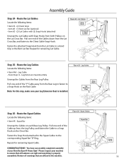
... to a Snap Hook on the Lat Cross Bar. Repeat for remaining Lat Cable. Please inspect your Bowflex Sport® Home Gym! Leg Cable • From Step 14 - You have successfully completed assembly of the "Y" Cable away from the Rear Leg Pulley. Squat Cables Squat Bar Snap Hook Snap Hook... Snap Hooks (attached) Unwrap the Lat Cables with Snap Hooks from the Lat Cable to the Chest Cable Snap Hook. Leg Extension Seat Assembly Unwrap the Cables from the Rear Leg to fasten to the corresponding Squat Bar "D" Ring. Repeat for remaining Squat Cable. Leg Cables Snap ...
... to a Snap Hook on the Lat Cross Bar. Repeat for remaining Lat Cable. Please inspect your Bowflex Sport® Home Gym! Leg Cable • From Step 14 - You have successfully completed assembly of the "Y" Cable away from the Rear Leg Pulley. Squat Cables Squat Bar Snap Hook Snap Hook... Snap Hooks (attached) Unwrap the Lat Cables with Snap Hooks from the Lat Cable to the Chest Cable Snap Hook. Leg Extension Seat Assembly Unwrap the Cables from the Rear Leg to fasten to the corresponding Squat Bar "D" Ring. Repeat for remaining Squat Cable. Leg Cables Snap ...

