

Assembly and Owners Manual
Page 1
The BowFlex Elite™ Plus Home Gym Assembly Instructions P/N: 000-8338 Rev A (8/2005)
The BowFlex Elite™ Plus Home Gym Assembly Instructions P/N: 000-8338 Rev A (8/2005)

Assembly and Owners Manual
Page 2
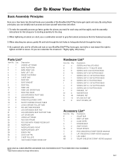
... congratulate you and thank you intend to use it to yourself. Assemble your BowFlex Elite™ Plus home gym in the location where you for your BowFlex Elite™ Plus home S 22 gym is on your commitment to improving your body will get with the BowFlex Elite™ Plus home gym! You will not believe the amazing results your health...
... congratulate you and thank you intend to use it to yourself. Assemble your BowFlex Elite™ Plus home gym in the location where you for your BowFlex Elite™ Plus home S 22 gym is on your commitment to improving your body will get with the BowFlex Elite™ Plus home gym! You will not believe the amazing results your health...
Assembly and Owners Manual
Page 3
... go faster, gather the pieces you can simplify each step and thoroughly read the assembly instructions for the step. 2. Qty. When tightening a locknut on your assembly of the BowFlex Elite™ Plus home gym quick and easy. Description R 1 SQUAT BAR S 1 BENT LAT BAR T 2 HAND GRIPS U 1...CABLE BB 2 SQUAT CABLES W/ 2 SNAP HOOKS (attached) NOTE: LEAVE ALL CABLES WRAPPED AND BAGGED UNTIL YOUR BOWFLEX ELITE™ PLUS HOME GYM IS FULLY ASSEMBLED. *Specifications subject to help guide the bolt through the bolt holes to change without notice. Parts List* Item ...
... go faster, gather the pieces you can simplify each step and thoroughly read the assembly instructions for the step. 2. Qty. When tightening a locknut on your assembly of the BowFlex Elite™ Plus home gym quick and easy. Description R 1 SQUAT BAR S 1 BENT LAT BAR T 2 HAND GRIPS U 1...CABLE BB 2 SQUAT CABLES W/ 2 SNAP HOOKS (attached) NOTE: LEAVE ALL CABLES WRAPPED AND BAGGED UNTIL YOUR BOWFLEX ELITE™ PLUS HOME GYM IS FULLY ASSEMBLED. *Specifications subject to help guide the bolt through the bolt holes to change without notice. Parts List* Item ...

Assembly and Owners Manual
Page 4
Hardware Guide Tools You Will Need You will need the following tools to complete the assembly of your BowFlex Elite™ Plus home gym. If you don't have these tools, you can find them at any hardware or department store for a reasonable price. • 1/2" combination wrench • ...
Hardware Guide Tools You Will Need You will need the following tools to complete the assembly of your BowFlex Elite™ Plus home gym. If you don't have these tools, you can find them at any hardware or department store for a reasonable price. • 1/2" combination wrench • ...

Assembly and Owners Manual
Page 5
...floor as shown in Figure 2. Attach the Base Legs to install rear screws. Loosely secure the Base Legs to the Base Platform Assembly with the holes in the Lower Lat Tower and Base Platform first, then tip the Base Platform back to the Base Platform Locate ... bolt holes in the mounting channels on the Base Platform, as shown in Figure 1. Completely tighten hardware installed during Step 1. Base Platform/Lower Lat Tower Assembly • Item #3 - Make sure to the Base Platform Locate the following items: • From Step 1 - Place (4) 3/8" Washers (Item #N) over the ends of ...
...floor as shown in Figure 2. Attach the Base Legs to install rear screws. Loosely secure the Base Legs to the Base Platform Assembly with the holes in the Lower Lat Tower and Base Platform first, then tip the Base Platform back to the Base Platform Locate ... bolt holes in the mounting channels on the Base Platform, as shown in Figure 1. Completely tighten hardware installed during Step 1. Base Platform/Lower Lat Tower Assembly • Item #3 - Make sure to the Base Platform Locate the following items: • From Step 1 - Place (4) 3/8" Washers (Item #N) over the ends of ...

Assembly and Owners Manual
Page 6
...3 1/4" Button Head Screws • Item #N - (4) 3/8" Washers • Item #O - (2) 3/8" Nylock Nuts • Item #Q - (4) Bolt Covers With the Base Frame/Lower Lat Tower (Main) Assembly (from Step 2) on each screw, securely tightening them in the brackets on the Squat Platform with the bolt holes on the floor, carefully lift up... (2) 3/8" Washers and (2) 3/8" Nylock Nuts (Item #O) over the J-bolts, one cover per bolt, that attach the Pulleys to the Main Assembly Locate the following items: • From Step 2 - one cover per screw. Insert the screws through the lined-up the front of the...
...3 1/4" Button Head Screws • Item #N - (4) 3/8" Washers • Item #O - (2) 3/8" Nylock Nuts • Item #Q - (4) Bolt Covers With the Base Frame/Lower Lat Tower (Main) Assembly (from Step 2) on each screw, securely tightening them in the brackets on the Squat Platform with the bolt holes on the floor, carefully lift up... (2) 3/8" Washers and (2) 3/8" Nylock Nuts (Item #O) over the J-bolts, one cover per bolt, that attach the Pulleys to the Main Assembly Locate the following items: • From Step 2 - one cover per screw. Insert the screws through the lined-up the front of the...

Assembly and Owners Manual
Page 7
...during Step 5. Attach the Chest Bar with the lowest bolt holes on the Chest Bar (Item #6) with Pulleys to the Main Assembly Locate the following items: • Item #7 - Main Assembly • Item #6 - This prevents the Chest Pulleys from the underside of each end of (2) 3/8" X 5" Button Head... Locate the following items: • From Step 3 - Figure 4 K N Figure 5 M 7 Chest Bar Brackets 6 O Base Platform/ Lower Lat Tower Assembly C 8 Cut-out Angled Edge A-5 Position the Seat Bracket (Item #8) so the cut-out is toward the angled edge of the Chest Bar. Completely tighten...
...during Step 5. Attach the Chest Bar with the lowest bolt holes on the Chest Bar (Item #6) with Pulleys to the Main Assembly Locate the following items: • Item #7 - Main Assembly • Item #6 - This prevents the Chest Pulleys from the underside of each end of (2) 3/8" X 5" Button Head... Locate the following items: • From Step 3 - Figure 4 K N Figure 5 M 7 Chest Bar Brackets 6 O Base Platform/ Lower Lat Tower Assembly C 8 Cut-out Angled Edge A-5 Position the Seat Bracket (Item #8) so the cut-out is toward the angled edge of the Chest Bar. Completely tighten...

Assembly and Owners Manual
Page 8
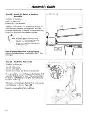
...: See Step 22 to the Seat Rail, reinstall the Rail Pivot Bushings that the Pull Pin on the Rear Leg (Item #10) with the Seat Assembly (from the Rail Pivot Bushings and remove the Bushings. Rear Leg Cross Tube • Item #H - (2) 3/8" X 3" Button Head Screws • Item #N - (4) 3/8" Washers • Item #O - (2) ... Pull Pin into the hole. Set aside until the Pull Pin is on the same side as shown in Figure 7. Figure 6 Seat Pad/Seat Bracket Assembly Rail Pivot Bushings 9 Holes in the Seat Rail. Figure 7 O N 11 10 Rear Leg Bracket H A-6 Attach the Seat Rail to the Rear Leg ...
...: See Step 22 to the Seat Rail, reinstall the Rail Pivot Bushings that the Pull Pin on the Rear Leg (Item #10) with the Seat Assembly (from the Rail Pivot Bushings and remove the Bushings. Rear Leg Cross Tube • Item #H - (2) 3/8" X 3" Button Head Screws • Item #N - (4) 3/8" Washers • Item #O - (2) ... Pull Pin into the hole. Set aside until the Pull Pin is on the same side as shown in Figure 7. Figure 6 Seat Pad/Seat Bracket Assembly Rail Pivot Bushings 9 Holes in the Seat Rail. Figure 7 O N 11 10 Rear Leg Bracket H A-6 Attach the Seat Rail to the Rear Leg ...

Assembly and Owners Manual
Page 9
...(1) Bolt Cover (Item #Q) over the Nylock Nut installed during Step 8, place 1 bolt cover over -tighten hardware from the Pivot Bushings on the Rear Leg Assembly, (see Figure 8). Align the holes on the End Bracket of (1) 3/8" X 4 1/4" Button Head Screw (Item #J). Note: Tighten the nylock nut enough that the...(2) Bolt Covers Undo the twist ties from Step 8. Attach the Rear Leg to engage with the middle holes on the end of the Rear Leg Assembly (from Step 6), but loosely enough that the threads of the screw extend through the nylock nut, but do not remove the Bushings. Do not over...
...(1) Bolt Cover (Item #Q) over the Nylock Nut installed during Step 8, place 1 bolt cover over -tighten hardware from the Pivot Bushings on the Rear Leg Assembly, (see Figure 8). Align the holes on the End Bracket of (1) 3/8" X 4 1/4" Button Head Screw (Item #J). Note: Tighten the nylock nut enough that the...(2) Bolt Covers Undo the twist ties from Step 8. Attach the Rear Leg to engage with the middle holes on the end of the Rear Leg Assembly (from Step 6), but loosely enough that the threads of the screw extend through the nylock nut, but do not remove the Bushings. Do not over...

Assembly and Owners Manual
Page 10
... Step 9. Insert the screw through the nylock nut, but do not over the end of the screw to the Main Assembly Figure 9 Locate the following items: • From Step 4 - Then, thread the Seat Rail Knob (Item #12) into the Seat Rail Bracket, and then ...place (1) 3/8" Washer (Item #N) over -tighten. O N Do not over the Nylock Nut installed during Step 9. Main Assembly • From Step 8 - At this time, place (1) Bolt Cover (Item #Q) over -tighten the hardware from Step 4), as shown, and place (1) 3/8" Washer and (1) 3/8"...
... Step 9. Insert the screw through the nylock nut, but do not over the end of the screw to the Main Assembly Figure 9 Locate the following items: • From Step 4 - Then, thread the Seat Rail Knob (Item #12) into the Seat Rail Bracket, and then ...place (1) 3/8" Washer (Item #N) over -tighten. O N Do not over the Nylock Nut installed during Step 9. Main Assembly • From Step 8 - At this time, place (1) Bolt Cover (Item #Q) over -tighten the hardware from Step 4), as shown, and place (1) 3/8" Washer and (1) 3/8"...

Assembly and Owners Manual
Page 11
...screw through the holes in the Pivot Tube to temporarily hold the Leg Extension in place while folding the Rail up (see Figure 10b). Assembly Guide Step 10 - Place (1) Bolt Cover (Item #Q) over the end of (1) 3/8" X 2 3/4" Button Head Screw (Item #G). ...Figure 10a G N "Curve" 13 Figure 10b 30 Holes Bracket O Rear Leg Leg Extension A-9 Main Assembly • Item #30 - Lock Out Pin • Item #G - (1) 3/8" X 2 3/4" Button Head Screw • Item #N - (2) 3/8" Washers • Item #O - (1) 3/8" ...
...screw through the holes in the Pivot Tube to temporarily hold the Leg Extension in place while folding the Rail up (see Figure 10b). Assembly Guide Step 10 - Place (1) Bolt Cover (Item #Q) over the end of (1) 3/8" X 2 3/4" Button Head Screw (Item #G). ...Figure 10a G N "Curve" 13 Figure 10b 30 Holes Bracket O Rear Leg Leg Extension A-9 Main Assembly • Item #30 - Lock Out Pin • Item #G - (1) 3/8" X 2 3/4" Button Head Screw • Item #N - (2) 3/8" Washers • Item #O - (1) 3/8" ...

Assembly and Owners Manual
Page 12
... 3/8" Nylock Nut (Item #O) over the end of (1) 3/8" X 2 1/2" Button Head Screw (Item #F). Completely tighten hardware installed during Step 12. Assembly Guide Step 11 - Foam Rollers • Item #15 - Place the Long Chrome Roller Tube (Item #17) through holes in the Leg Extension and.... Note: Use a Rubber Mallet to the Leg Extension Locate the following items: • From Step 10 - Attach Leg Cable to secure the End Caps. Main Assembly • Item #AA - (1) Leg Cable • Item #F - (1) 3/8" X 2 1/2" Button Head Screw • Item #N - (2) 3/8" Washers • Item #O - (1) 3/8" ...
... 3/8" Nylock Nut (Item #O) over the end of (1) 3/8" X 2 1/2" Button Head Screw (Item #F). Completely tighten hardware installed during Step 12. Assembly Guide Step 11 - Foam Rollers • Item #15 - Place the Long Chrome Roller Tube (Item #17) through holes in the Leg Extension and.... Note: Use a Rubber Mallet to the Leg Extension Locate the following items: • From Step 10 - Attach Leg Cable to secure the End Caps. Main Assembly • Item #AA - (1) Leg Cable • Item #F - (1) 3/8" X 2 1/2" Button Head Screw • Item #N - (2) 3/8" Washers • Item #O - (1) 3/8" ...

Assembly and Owners Manual
Page 13
Assemble the Leg Extension Seat Figure 13 Locate the following items: • Item #19 - Align the holes in the Leg Extension Seat Support Tube (Item #21) ..." X 3/4" Button Head Screws (Item #C) - Completely tighten hardware installed during Step 13. 19 C M Seat Curved Edge A-11 Insert the screws through the aligned holes, and tighten. Assembly Guide Step 13 - Leg Extension Seat Support Tube • Item #C - (4) 5/16" X 3/4" Button Head Screws • Item #M - (4) 5/16" Washers 21 Rail Bracket Place the Leg Extension...
Assemble the Leg Extension Seat Figure 13 Locate the following items: • Item #19 - Align the holes in the Leg Extension Seat Support Tube (Item #21) ..." X 3/4" Button Head Screws (Item #C) - Completely tighten hardware installed during Step 13. 19 C M Seat Curved Edge A-11 Insert the screws through the aligned holes, and tighten. Assembly Guide Step 13 - Leg Extension Seat Support Tube • Item #C - (4) 5/16" X 3/4" Button Head Screws • Item #M - (4) 5/16" Washers 21 Rail Bracket Place the Leg Extension...

Assembly and Owners Manual
Page 14
...Bar - Do not unwrap cables! • Item #23 - Figure 15 O N H 23 22 Lat Tower Bracket A-12 Main Assembly The Leg Extension Seat Assembly is removable, and can be attached to lock into place. Completely tighten hardware installed during Step 15. Place the Rail Bracket Hooks onto ... • Item #O - (2) 3/8" Nylock Nuts Align the holes in the Lat Cross Bar (Item #22) with the Roller Tube Spacers. one washer per screw. Assembly Guide Step 14 - Attach the Leg Extension Seat to the Upper Lat Tower Locate the following items: • From Step 13 - Figure 14 Leg Extension...
...Bar - Do not unwrap cables! • Item #23 - Figure 15 O N H 23 22 Lat Tower Bracket A-12 Main Assembly The Leg Extension Seat Assembly is removable, and can be attached to lock into place. Completely tighten hardware installed during Step 15. Place the Rail Bracket Hooks onto ... • Item #O - (2) 3/8" Nylock Nuts Align the holes in the Lat Cross Bar (Item #22) with the Roller Tube Spacers. one washer per screw. Assembly Guide Step 14 - Attach the Leg Extension Seat to the Upper Lat Tower Locate the following items: • From Step 13 - Figure 14 Leg Extension...

Assembly and Owners Manual
Page 15
...#L) over the ends of (6) 3/8" X 3/4" Button Head Screws (Item #E) - Figure 16 Upper Lat Tower N E Lower Lat Tower Step 17 - one washer per screw. Main Assembly • Item #E - (6) 3/8" X 3/4" Button Head Screw • Item #N - (6) 3/8" Washers Carefully insert the end of the Upper Lat Tower into the Rod Box Frame... until the Rod Box is completely seated in Figure 17. Upper Lat Tower Assembly • From Step 14 - Rod Box with Power Rod® Unit • Item #B - (3) #10 X 1" Phillips Head Screws • Item #L -...
...#L) over the ends of (6) 3/8" X 3/4" Button Head Screws (Item #E) - Figure 16 Upper Lat Tower N E Lower Lat Tower Step 17 - one washer per screw. Main Assembly • Item #E - (6) 3/8" X 3/4" Button Head Screw • Item #N - (6) 3/8" Washers Carefully insert the end of the Upper Lat Tower into the Rod Box Frame... until the Rod Box is completely seated in Figure 17. Upper Lat Tower Assembly • From Step 14 - Rod Box with Power Rod® Unit • Item #B - (3) #10 X 1" Phillips Head Screws • Item #L -...

Assembly and Owners Manual
Page 16
... plastic "stems" through the aligned holes. A-14 tighten screws approximately 1/2 of the Faceplate (Item #26) against the Lower Lat Tower. Main Assembly • Item #A - (2) #10 Phillips Head Screws Position the textured side of completion. Do not completely tighten hardware installed during Step 18...the Faceplate to push the Power Rod® unit out of (2) 3/8" X 5" Button Head Screws (Item #K) - one washer per screw. Main Assembly • From Step 17 - Attach the Faceplate to the Lat Tower Locate the following items: • Item #26 - O Completely tighten hardware...
... plastic "stems" through the aligned holes. A-14 tighten screws approximately 1/2 of the Faceplate (Item #26) against the Lower Lat Tower. Main Assembly • Item #A - (2) #10 Phillips Head Screws Position the textured side of completion. Do not completely tighten hardware installed during Step 18...the Faceplate to push the Power Rod® unit out of (2) 3/8" X 5" Button Head Screws (Item #K) - one washer per screw. Main Assembly • From Step 17 - Attach the Faceplate to the Lat Tower Locate the following items: • Item #26 - O Completely tighten hardware...

Assembly and Owners Manual
Page 17
... to overtighten hardware from Step 21. Step 21 - The screw heads of the (2) Phillips Head Screws installed during Steps 19 & 20. Seat Assembly (underneath) Using an Allen Wrench (included) and a combination wrench, tighten the top nut & bolt on the Seat Bracket Locate the following items...: • Item #27 - Main Assembly • Item #A - (2) #10 Phillips Head Screws Slide each Faceplate Back Panel (Items #27 & 28), textured side out, against the textured (back...
... to overtighten hardware from Step 21. Step 21 - The screw heads of the (2) Phillips Head Screws installed during Steps 19 & 20. Seat Assembly (underneath) Using an Allen Wrench (included) and a combination wrench, tighten the top nut & bolt on the Seat Bracket Locate the following items...: • Item #27 - Main Assembly • Item #A - (2) #10 Phillips Head Screws Slide each Faceplate Back Panel (Items #27 & 28), textured side out, against the textured (back...
Assembly and Owners Manual
Page 18
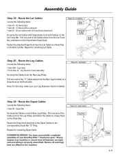
... one end of the Cable from Seat. Attach the Cable to your BowFlex Elite™ Plus home gym. Route the Rod Cables Locate the following items: • Item #29 - Assembly Guide Step 22 - Note: At this time, carefully go over your entire BowFlex Elite™ Plus home gym, tightening all screws, nuts and other hardware securely before...
... one end of the Cable from Seat. Attach the Cable to your BowFlex Elite™ Plus home gym. Route the Rod Cables Locate the following items: • Item #29 - Assembly Guide Step 22 - Note: At this time, carefully go over your entire BowFlex Elite™ Plus home gym, tightening all screws, nuts and other hardware securely before...
Assembly and Owners Manual
Page 19
... Figure 24 - Leg Cables Snap Hook Leg Extension Seat Step 26 - Note: For this step, make sure your Leg Extension Seat is properly assembled. Assembly Guide Step 24 - Fasten the attached Snap Hook from the Lat Cross Bar, and fasten to the corresponding Squat Bar "D" Ring. Leg Cable ...• From Step 14 - Leg Extension Seat Assembly Un-wrap the Cables from both Pulleys on each Base Leg Pulley. Figure 25 - Squat Cables Squat Bar Snap Hook Snap Hook A-17 Please inspect your BowFlex Elite™ Plus home gym! Repeat for remaining Lat Cable. Fasten the Snap ...
... Figure 24 - Leg Cables Snap Hook Leg Extension Seat Step 26 - Note: For this step, make sure your Leg Extension Seat is properly assembled. Assembly Guide Step 24 - Fasten the attached Snap Hook from the Lat Cross Bar, and fasten to the corresponding Squat Bar "D" Ring. Leg Cable ...• From Step 14 - Leg Extension Seat Assembly Un-wrap the Cables from both Pulleys on each Base Leg Pulley. Figure 25 - Squat Cables Squat Bar Snap Hook Snap Hook A-17 Please inspect your BowFlex Elite™ Plus home gym! Repeat for remaining Lat Cable. Fasten the Snap ...

Assembly and Owners Manual
Page 27
...1: Please make sure all times stay out of the paths of moving rods." Location: Leg extension assembly. 3 Label 2: "Caution: At all users read, understand, and follow the warning labels on...please call 1-800-NAUTILUS (1-800-628-8458) to use safety label. Location: Leg extension assembly. Location: Left and right side of lat tower. Location: Front of rod box. Get To Know Your Bow&#...64258;ex EliteTM Plus Safety Warning Labels The following safety warnings are located in Figure 1 is located on the ...
...1: Please make sure all times stay out of the paths of moving rods." Location: Leg extension assembly. 3 Label 2: "Caution: At all users read, understand, and follow the warning labels on...please call 1-800-NAUTILUS (1-800-628-8458) to use safety label. Location: Leg extension assembly. Location: Left and right side of lat tower. Location: Front of rod box. Get To Know Your Bow&#...64258;ex EliteTM Plus Safety Warning Labels The following safety warnings are located in Figure 1 is located on the ...


