User Manual
Page 5
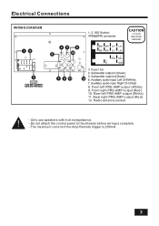
Electrical Connections WIRING DIAGRAM CAUTION +12V DC NEGATIVE GROUND 15A 15A 15 8. Do not attach the control panel to the chassis before wiring is 200mA. 3 The maximum current of the Amp Remote trigger is complete. - Radio antenna socket - Rear left PRE-AMP output (White) 9. Rear right PRE-AMP output (Red) 12. Only use speakers with 4 ohm impedance. - Front right PRE-AMP output (Red) 10. Front left PRE-AMP output (White) 11.
Electrical Connections WIRING DIAGRAM CAUTION +12V DC NEGATIVE GROUND 15A 15A 15 8. Do not attach the control panel to the chassis before wiring is 200mA. 3 The maximum current of the Amp Remote trigger is complete. - Radio antenna socket - Rear left PRE-AMP output (White) 9. Rear right PRE-AMP output (Red) 12. Only use speakers with 4 ohm impedance. - Front right PRE-AMP output (Red) 10. Front left PRE-AMP output (White) 11.
User Manual V2
Page 5
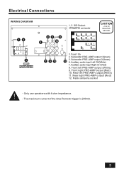
Rear left PRE-AMP output (White) 9. Only use speakers with 4 ohm impedance. - Front left PRE-AMP output (White) 11. The maximum current of the Amp Remote trigger is 200mA. 3 Rear right PRE-AMP output (Red) 12. Radio antenna socket - Electrical Connections WIRING DIAGRAM CAUTION +12V DC NEGATIVE GROUND 15A 15A 15 8. Front right PRE-AMP output (Red) 10.
Rear left PRE-AMP output (White) 9. Only use speakers with 4 ohm impedance. - Front left PRE-AMP output (White) 11. The maximum current of the Amp Remote trigger is 200mA. 3 Rear right PRE-AMP output (Red) 12. Radio antenna socket - Electrical Connections WIRING DIAGRAM CAUTION +12V DC NEGATIVE GROUND 15A 15A 15 8. Front right PRE-AMP output (Red) 10.


