Installation guide
Page 2
...in this installation guide carefully. Please read this installation guide Please take the time to EN 60825-1:1994 + A11. Save your LIFESTYLE® media center and Acoustimass® module enclosures: The lightning flash with arrowhead symbol, within an equilateral triangle, is intended to alert the ...user to the presence of uninsulated dangerous voltage within the media center is classified as lighted candles, should not be placed on the system, is located on the Important Safety Information sheet enclosed ...
...in this installation guide carefully. Please read this installation guide Please take the time to EN 60825-1:1994 + A11. Save your LIFESTYLE® media center and Acoustimass® module enclosures: The lightning flash with arrowhead symbol, within an equilateral triangle, is intended to alert the ...user to the presence of uninsulated dangerous voltage within the media center is classified as lighted candles, should not be placed on the system, is located on the Important Safety Information sheet enclosed ...
Installation guide
Page 3
System: (circle one) LIFESTYLE® 18 system LIFESTYLE® 28 system LIFESTYLE® 38 system LIFESTYLE® 48 system Media center serial number Acoustimass module serial number Dealer name Dealer phone Purchase date Be sure to the copyright protection ...used without prior written permission. "DTS" and "DTS Digital Surround" are registered trademarks of this guide. ©2004 Bose Corporation. and is limited solely to Bose. Reverse engineering or disassembly is protected by Macrovision Corporation, and is prohibited. Confidential Unpublished Works. ©1992-1997 Dolby...
System: (circle one) LIFESTYLE® 18 system LIFESTYLE® 28 system LIFESTYLE® 38 system LIFESTYLE® 48 system Media center serial number Acoustimass module serial number Dealer name Dealer phone Purchase date Be sure to the copyright protection ...used without prior written permission. "DTS" and "DTS Digital Surround" are registered trademarks of this guide. ©2004 Bose Corporation. and is limited solely to Bose. Reverse engineering or disassembly is protected by Macrovision Corporation, and is prohibited. Confidential Unpublished Works. ©1992-1997 Dolby...
Installation guide
Page 4
... Cube® speakers 12 Making the two-wire connections for cube or cube array speakers 13 Connecting the Acoustimass module to the media center 15 Connecting the antennas 16 Connecting the FM antenna 16 Connecting the AM antenna 16 Connecting to a cable radio provider 16 Connecting... other components 29 Connecting record/playback equipment 29 Connecting other playback equipment 29 Using digital audio connections 30 Other jacks on the media center panel 31 Connecting an optional antenna extender 31 Connecting the optional IR emitter cable 31 Data port for system backups 31 Serial ...
... Cube® speakers 12 Making the two-wire connections for cube or cube array speakers 13 Connecting the Acoustimass module to the media center 15 Connecting the antennas 16 Connecting the FM antenna 16 Connecting the AM antenna 16 Connecting to a cable radio provider 16 Connecting... other components 29 Connecting record/playback equipment 29 Connecting other playback equipment 29 Using digital audio connections 30 Other jacks on the media center panel 31 Connecting an optional antenna extender 31 Connecting the optional IR emitter cable 31 Data port for system backups 31 Serial ...
Installation guide
Page 5
..., cable or satellite boxes, DVD changers, game consoles, and recording equipment, to the Bose address list included in different countries. Refer to make an even more versatile home theater ... LIFESTYLE® 38, and LIFESTYLE® 48 systems have one of the three types of the system. Your Operating Guide offers information on the next two pages will serve as the center ...the use of your system. First you become familiar with your system. Unpacking After unpacking your media center, cube speakers, and Acoustimass® module. The drawings on page 32 before you : ...
..., cable or satellite boxes, DVD changers, game consoles, and recording equipment, to the Bose address list included in different countries. Refer to make an even more versatile home theater ... LIFESTYLE® 38, and LIFESTYLE® 48 systems have one of the three types of the system. Your Operating Guide offers information on the next two pages will serve as the center ...the use of your system. First you become familiar with your system. Unpacking After unpacking your media center, cube speakers, and Acoustimass® module. The drawings on page 32 before you : ...
Installation guide
Page 6
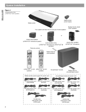
... Seek Shuffle Repeat 1 2 3 4 5 6 7 8 9 Info Last 0 uMusic Rating Similar Whole CD CD # Playlist Rubber feet for cube speakers LIFESTYLE® 18, 28 LIFESTYLE® 38, 48 systems systems Acoustimass® module Rubber feet for Acoustimass module Media center power supply AC power cord Acoustimass module AC power cord 120 VAC power cord 230 VAC power cord...
... Seek Shuffle Repeat 1 2 3 4 5 6 7 8 9 Info Last 0 uMusic Rating Similar Whole CD CD # Playlist Rubber feet for cube speakers LIFESTYLE® 18, 28 LIFESTYLE® 38, 48 systems systems Acoustimass® module Rubber feet for Acoustimass module Media center power supply AC power cord Acoustimass module AC power cord 120 VAC power cord 230 VAC power cord...
Installation guide
Page 7
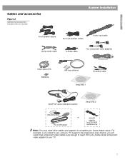
... on/off sensor or SCART adapter for 220-240V systems only Note: You may need three component video cables long enough to reach from your media center component video adapter to complete your TV. 7 For example, if you intend to use, and your TV supports the progressive scan feature, you will need...
... on/off sensor or SCART adapter for 220-240V systems only Note: You may need three component video cables long enough to reach from your media center component video adapter to complete your TV. 7 For example, if you intend to use, and your TV supports the progressive scan feature, you will need...
Installation guide
Page 11
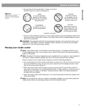
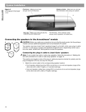
... (Figure 6). Placing your dealer or call Bose® customer service. Also, be sure you should not store tapes directly on the bottom of the media center (Figure 7). • Place the media center close enough to connect your components, see your media center Note: If the serial number on or ...of the bottom surface. Note: For convenience, until your system, is completely installed, you may wish to place the media center where you want to the Bose address list included with the connectors facing the floor. English System Installation Figure 6 Right and wrong placements for the ...
... (Figure 6). Placing your dealer or call Bose® customer service. Also, be sure you should not store tapes directly on the bottom of the media center (Figure 7). • Place the media center close enough to connect your components, see your media center Note: If the serial number on or ...of the bottom surface. Note: For convenience, until your system, is completely installed, you may wish to place the media center where you want to the Bose address list included with the connectors facing the floor. English System Installation Figure 6 Right and wrong placements for the ...
Installation guide
Page 12
Display window - LIFESTYLE® DVD systems include five speakers. Make sure you have enough room to...Connecting the speakers to the Acoustimass® module A B CAUTION: Before you make any connections, be sure that the media center, the Acoustimass module, and any additional equipment are properly oriented for polarity and the plug is located here. Make sure... at the other end with L (left) or R (right) markings. 12 The positive and negative wires of the media center Front door - Make sure you can see this The IR Emitter, which use a plug-in cable connect, or cube...
Display window - LIFESTYLE® DVD systems include five speakers. Make sure you have enough room to...Connecting the speakers to the Acoustimass® module A B CAUTION: Before you make any connections, be sure that the media center, the Acoustimass module, and any additional equipment are properly oriented for polarity and the plug is located here. Make sure... at the other end with L (left) or R (right) markings. 12 The positive and negative wires of the media center Front door - Make sure you can see this The IR Emitter, which use a plug-in cable connect, or cube...
Installation guide
Page 15
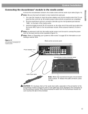
...in place. To release the cable connector, press the tab. English System Installation Connecting the Acoustimass® module to the media center Connect the Acoustimass module to insert the power adapter cord into the Speakers jack labeled "Main" on the Acoustimass module. ... into the Audio INPUT jack on the back of the media center. 3. Note: Be sure that each jack. 1. Figure 11 Acoustimass connection to the Acoustimass module. Excessive strain on the connection to media center Media center connector panel Power adapter cord 1 Acoustimass module connector panel Audio...
...in place. To release the cable connector, press the tab. English System Installation Connecting the Acoustimass® module to the media center Connect the Acoustimass module to insert the power adapter cord into the Speakers jack labeled "Main" on the Acoustimass module. ... into the Audio INPUT jack on the back of the media center. 3. Note: Be sure that each jack. 1. Figure 11 Acoustimass connection to the Acoustimass module. Excessive strain on the connection to media center Media center connector panel Power adapter cord 1 Acoustimass module connector panel Audio...

Installation guide
Page 16
... antenna jack. 2. Stand the loop antenna on a wall, follow the instructions enclosed with the antenna. 1. Experiment with the orientation of the media center. This connection is received by your television. Figure 12 Connections for assistance. Place the antenna as possible. Note: AM radio reception may be...jack. Move the AM loop antenna as far as possible, at least 20 inches (50 cm), from the media center, and at least 2 feet (60 cm) from the media center and other components as far from the Acoustimass® module. Follow all safety instructions supplied with the antenna. If...
... antenna jack. 2. Stand the loop antenna on a wall, follow the instructions enclosed with the antenna. 1. Experiment with the orientation of the media center. This connection is received by your television. Figure 12 Connections for assistance. Place the antenna as possible. Note: AM radio reception may be...jack. Move the AM loop antenna as far as possible, at least 20 inches (50 cm), from the media center, and at least 2 feet (60 cm) from the media center and other components as far from the Acoustimass® module. Follow all safety instructions supplied with the antenna. If...
Installation guide
Page 17
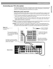
...system. This may have a digital TV, you to your TV remote control to select VIDEO 1 to view DVDs and see system menus Media Center 17 In the example below show basic connections to notice which has a unique snap fit connector on the rear panel of connections will allow... fixed (FIX) and variable (VAR) outputs, use the ones for connecting additional components to view DVDs and see LIFESTYLE® system menus. It may either be sure to the media center and TV. Making the audio connection Using the supplied stereo audio cable, connect the left (L) and right (R) audio...
...system. This may have a digital TV, you to your TV remote control to select VIDEO 1 to view DVDs and see system menus Media Center 17 In the example below show basic connections to notice which has a unique snap fit connector on the rear panel of connections will allow... fixed (FIX) and variable (VAR) outputs, use the ones for connecting additional components to view DVDs and see LIFESTYLE® system menus. It may either be sure to the media center and TV. Making the audio connection Using the supplied stereo audio cable, connect the left (L) and right (R) audio...
Installation guide
Page 18
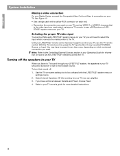
... for more than once, depending on -screen setting (not to control the TV. Use the TV on which connects the media center to your TV should be turned off or set the LIFESTYLE® remote to be called TV/VIDEO, Source, or Input. With the TV remote control, press the TV input button...
... for more than once, depending on -screen setting (not to control the TV. Use the TV on which connects the media center to your TV should be turned off or set the LIFESTYLE® remote to be called TV/VIDEO, Source, or Input. With the TV remote control, press the TV input button...
Installation guide
Page 19
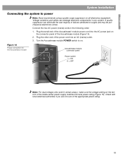
... outlet. 3. Note: For dual voltage units (sold in certain areas), make sure the voltage setting on the connector panel of the media center power supply matches the local power rating (Figure 15). Check with local electrical authorities if you are not sure of failures attributed to... ON O = OFF L R POWER 100-120/200-240VAC 50/60 Hz 350W MAX. English System Installation Connecting the system to power Note: Bose recommends using a quality surge suppressor on . Turn the Acoustimass module POWER switch to on all electronics equipment. Voltage variations and spikes can eliminate the...
... outlet. 3. Note: For dual voltage units (sold in certain areas), make sure the voltage setting on the connector panel of the media center power supply matches the local power rating (Figure 15). Check with local electrical authorities if you are not sure of failures attributed to... ON O = OFF L R POWER 100-120/200-240VAC 50/60 Hz 350W MAX. English System Installation Connecting the system to power Note: Bose recommends using a quality surge suppressor on . Turn the Acoustimass module POWER switch to on all electronics equipment. Voltage variations and spikes can eliminate the...
Installation guide
Page 20
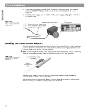
...power jack Media center connection panel Installing the remote control batteries Slide the battery compartment cover off of the back of the factory-preset miniature switches. See your TV. English System Installation 4. Your remote control will need to be "taught" to prevent conflicts with other LIFESTYLE ®...so now (Figure 15). 5. Note: Do not change the settings of the remote. See your Operating Guide for the media center Media center power supply Be sure the power supply cord is fully extended; it closed. Alkaline batteries are recommended. Figure 15 Power ...
...power jack Media center connection panel Installing the remote control batteries Slide the battery compartment cover off of the back of the factory-preset miniature switches. See your TV. English System Installation 4. Your remote control will need to be "taught" to prevent conflicts with other LIFESTYLE ®...so now (Figure 15). 5. Note: Do not change the settings of the remote. See your Operating Guide for the media center Media center power supply Be sure the power supply cord is fully extended; it closed. Alkaline batteries are recommended. Figure 15 Power ...

Installation guide
Page 22
You will explain the procedure you are to the LIFESTYLE® system media center. 3. Keep the headset and discs together in their instructions, the installation of the media center as shown below. Insert Setup Disc 1 into the tray (label side up the media center front cover and press the Open/Close button. 4. When Disc 2 indicates, connect the ADAPTiQ...
You will explain the procedure you are to the LIFESTYLE® system media center. 3. Keep the headset and discs together in their instructions, the installation of the media center as shown below. Insert Setup Disc 1 into the tray (label side up the media center front cover and press the Open/Close button. 4. When Disc 2 indicates, connect the ADAPTiQ...
Installation guide
Page 23
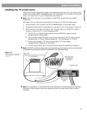
... jack on and off manually. 23 Change this automatic feature as you have tested and enabled this from "TV not detected" to turn on the LIFESTYLE® system remote. D. Test the sensor and enable the feature. Access Video/TV power status. In the menu navigate to control your TV" ... use the mounting strip to permanently mount the sensor until you follow the steps below: 1. With larger TVs you need to be turned on the media center. 2. See "Programming your TV separately. As one person moves the sensor near the rear vent area of TV TV on . English System Installation ...
... jack on and off manually. 23 Change this automatic feature as you have tested and enabled this from "TV not detected" to turn on the LIFESTYLE® system remote. D. Test the sensor and enable the feature. Access Video/TV power status. In the menu navigate to control your TV" ... use the mounting strip to permanently mount the sensor until you follow the steps below: 1. With larger TVs you need to be turned on the media center. 2. See "Programming your TV separately. As one person moves the sensor near the rear vent area of TV TV on . English System Installation ...
Installation guide
Page 24
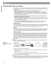
...note which jack you use the supplied Video cable (with yellow connectors) to go directly to the TV. Figure 20 The Bose component video adapter Media center S-VIDEO OUTPUT COMPOSITE VIDEO OUTPUT Component video adapter Video cables TV Component video jacks Y (Green) Pr (Red) Pb (...coaxial digital (single cable with your local electronics store or authorized Bose® dealer. Video-grade cables from the media center to the S-Video input on the following pages show variations that came with your media center. Component video If your want to use the system's progressive scan...
...note which jack you use the supplied Video cable (with yellow connectors) to go directly to the TV. Figure 20 The Bose component video adapter Media center S-VIDEO OUTPUT COMPOSITE VIDEO OUTPUT Component video adapter Video cables TV Component video jacks Y (Green) Pr (Red) Pb (...coaxial digital (single cable with your local electronics store or authorized Bose® dealer. Video-grade cables from the media center to the S-Video input on the following pages show variations that came with your media center. Component video If your want to use the system's progressive scan...
Installation guide
Page 25
...a VCR to the media center. If your media center is the type of the media center provides audio and video connections for higher DVD picture quality. Contact your local electronics store or authorized Bose® dealer. Most VCRs have already used the video and audio cables supplied with your LIFESTYLE® system, or... to the TV. The composite connection made in Step 2 above will pass the VCR video to the media center (Composite Video IN). Then use an S-Video cable to connect the media center (Video OUT) to your TV, for your VCR. You can use another input on the TV and ...
...a VCR to the media center. If your media center is the type of the media center provides audio and video connections for higher DVD picture quality. Contact your local electronics store or authorized Bose® dealer. Most VCRs have already used the video and audio cables supplied with your LIFESTYLE® system, or... to the TV. The composite connection made in Step 2 above will pass the VCR video to the media center (Composite Video IN). Then use an S-Video cable to connect the media center (Video OUT) to your TV, for your VCR. You can use another input on the TV and ...

Installation guide
Page 26
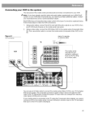
... Bose® dealer. Figure 22 Set top box and VCR Cable TV, satellite, or antenna cable If the CBL/SAT box has only a composite VIDEO OUT jack, connect that jack is unavailable, connect the VCR directly to the TV. Use another S-VIDEO cable to connect the S-VIDEO OUT jack on the media center.... Select the CBL/SAT sound source. If the cable/satellite box has an S-VIDEO OUT jack, connect it to the S-VIDEO IN jack on the media center. 2. English Reference Connecting your TV (or the TV input to which you directly connected the VCR) and select the VCR sound source. Connect a VCR to...
... Bose® dealer. Figure 22 Set top box and VCR Cable TV, satellite, or antenna cable If the CBL/SAT box has only a composite VIDEO OUT jack, connect that jack is unavailable, connect the VCR directly to the TV. Use another S-VIDEO cable to connect the S-VIDEO OUT jack on the media center.... Select the CBL/SAT sound source. If the cable/satellite box has an S-VIDEO OUT jack, connect it to the S-VIDEO IN jack on the media center. 2. English Reference Connecting your TV (or the TV input to which you directly connected the VCR) and select the VCR sound source. Connect a VCR to...
Installation guide
Page 27
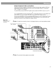
...VIDEO 4 on your LIFESTYLE® system remote. Component video adapter Component video adapter Note: Two comonent video adapters are provided. 27 Connect the VCR (Audio L and R OUT) to "Component video" on page 24, if necessary. Refer to the TV Audio IN jacks on the media center and select the ...TV source on your LIFESTYLE® system remote. Select that TV input. Select CBL/SAT on your TV. English Figure 23 Component video connection Reference Using...
...VIDEO 4 on your LIFESTYLE® system remote. Component video adapter Component video adapter Note: Two comonent video adapters are provided. 27 Connect the VCR (Audio L and R OUT) to "Component video" on page 24, if necessary. Refer to the TV Audio IN jacks on the media center and select the ...TV source on your LIFESTYLE® system remote. Select that TV input. Select CBL/SAT on your TV. English Figure 23 Component video connection Reference Using...


