Installation guide
Page 4
... sensor 23 Reference 24 Using alternate video connections 24 Connecting your VCR to the system 25 Connecting your cable/satellite box to the system 26 Using Component video connections 27 Connecting a game console 28 Connecting other components 29 Connecting record/playback equipment 29 Connecting other playback equipment 29 Using digital audio connections 30 Other jacks on the media center...
... sensor 23 Reference 24 Using alternate video connections 24 Connecting your VCR to the system 25 Connecting your cable/satellite box to the system 26 Using Component video connections 27 Connecting a game console 28 Connecting other components 29 Connecting record/playback equipment 29 Connecting other playback equipment 29 Using digital audio connections 30 Other jacks on the media center...
Installation guide
Page 5
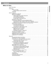
... room connections, most include the AdaptiQ® audio calibration system, and the LIFESTYLE® 38, and LIFESTYLE® 48 systems have the uMusic® intelligent playback system. However, if you wish to extend your system's sound to other rooms, read the special considerations in "Expanding your system to make any part of a Bose® LIFESTYLE®...
... room connections, most include the AdaptiQ® audio calibration system, and the LIFESTYLE® 38, and LIFESTYLE® 48 systems have the uMusic® intelligent playback system. However, if you wish to extend your system's sound to other rooms, read the special considerations in "Expanding your system to make any part of a Bose® LIFESTYLE®...
Installation guide
Page 11
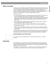
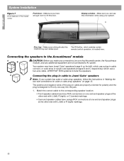
...audio tapes, and other sound sources (TV and VCR) to record it to Bose. Placing your media center Note: If the serial number on the front of this guide. Select a location for easy cable connections. Ventilation openings DO NOT stand the module on its slightly curved back end, which... module. DO NOT stand the module on the floor. Allow enough room to the Bose address list included with the connectors facing the floor. If you need additional audio or video cables to connect your components, see your system, is completely installed, you may wish to place the...
...audio tapes, and other sound sources (TV and VCR) to record it to Bose. Placing your media center Note: If the serial number on the front of this guide. Select a location for easy cable connections. Ventilation openings DO NOT stand the module on its slightly curved back end, which... module. DO NOT stand the module on the floor. Allow enough room to the Bose address list included with the connectors facing the floor. If you need additional audio or video cables to connect your components, see your system, is completely installed, you may wish to place the...
Installation guide
Page 12
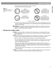
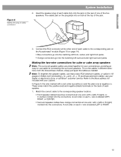
...and speaker plugs at one way into the jack. 1. English System Installation Figure 7 Front features of the plug-in cable are not connected to the corresponding speaker location: • Front speaker cables have enough room to Jewel Cube® speakers Note: If your system. ...) markings. • Surround speaker cables have orange RCA connectors at the other end with L (left ), which use a two-wire cable. LIFESTYLE® DVD systems include five speakers. The positive and negative wires of the media center Front door - Match the correct cable to AC power.
...and speaker plugs at one way into the jack. 1. English System Installation Figure 7 Front features of the plug-in cable are not connected to the corresponding speaker location: • Front speaker cables have enough room to Jewel Cube® speakers Note: If your system. ...) markings. • Surround speaker cables have orange RCA connectors at the other end with L (left ), which use a two-wire cable. LIFESTYLE® DVD systems include five speakers. The positive and negative wires of the media center Front door - Match the correct cable to AC power.
Installation guide
Page 13
...marked with L (left), R (right), or C (center) molded into the matching left surround and right surround jacks. Making the two-wire connections for cube or cube array speakers Note: The surround speaker cables are joined together for your convenience, providing an easy-to the corresponding jack on... apart the cables as needed. To purchase extension cables, see your system. Connect the RCA connector at one is positive (+) and the plain one end, with your dealer or electronics store, or call Bose® customer service. Refer to the corresponding speaker location. • Front ...
...marked with L (left), R (right), or C (center) molded into the matching left surround and right surround jacks. Making the two-wire connections for cube or cube array speakers Note: The surround speaker cables are joined together for your convenience, providing an easy-to the corresponding jack on... apart the cables as needed. To purchase extension cables, see your system. Connect the RCA connector at one is positive (+) and the plain one end, with your dealer or electronics store, or call Bose® customer service. Refer to the corresponding speaker location. • Front ...
Installation guide
Page 14
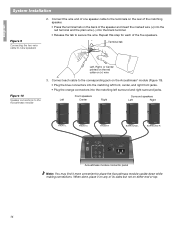
... FRONT C FRONT R SURROUND L SURROUND R AUDIO INPUT OUTPUTS TO CUBE SPEAKERS FRONT SURROUND L C L R R POWER 100-120/200-240VAC 50/60 Hz 350W MAX. Connect each of the matching speaker. • Press the terminal tab on either end or top. 14 Terminal tab Left, Right, or Center printed on the... red collar on (+) wire Figure 10 Speaker connections to cube speakers 2. Repeat this step for each cable to the corresponding jack on the Acoustimass® module (Figure 10). • Plug ...
... FRONT C FRONT R SURROUND L SURROUND R AUDIO INPUT OUTPUTS TO CUBE SPEAKERS FRONT SURROUND L C L R R POWER 100-120/200-240VAC 50/60 Hz 350W MAX. Connect each of the matching speaker. • Press the terminal tab on either end or top. 14 Terminal tab Left, Right, or Center printed on the... red collar on (+) wire Figure 10 Speaker connections to cube speakers 2. Repeat this step for each cable to the corresponding jack on the Acoustimass® module (Figure 10). • Plug ...
Installation guide
Page 15
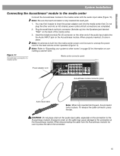
... press the tab. You may cause damage to insert the power adapter cord into the Audio INPUT jack on connecting a second room. When properly inserted, it easier to the connection at the Acoustimass module. CAUTION: Do not place strain on the audio input cable, especially on the other ...center power cord; Note: Be sure that each connector is built into each jack. 1. Insert the telephone-style RJ-45 connector on the connection to media center Media center connector panel Power adapter cord 1 Acoustimass module connector panel Audio input cable Note: When fully inserted into an AC ...
... press the tab. You may cause damage to insert the power adapter cord into the Audio INPUT jack on connecting a second room. When properly inserted, it easier to the connection at the Acoustimass module. CAUTION: Do not place strain on the audio input cable, especially on the other ...center power cord; Note: Be sure that each connector is built into each jack. 1. Insert the telephone-style RJ-45 connector on the connection to media center Media center connector panel Power adapter cord 1 Acoustimass module connector panel Audio input cable Note: When fully inserted into an AC ...

Installation guide
Page 16
...Some cable TV providers make FM radio signals available through the cable service to the FM antenna jack. CAUTION: Do not attempt to connect a television cable to your home. Place the antenna as possible. Experiment with the orientation of the loop for the AM and FM... antenna. If necessary, contact a qualified installer. 16 Follow all safety instructions supplied with the AM antenna. 3. English System Installation Connecting the antennas You should connect the additional AM and FM antennas, included with your system, to the FM antenna jack on the back panel of the media...
...Some cable TV providers make FM radio signals available through the cable service to the FM antenna jack. CAUTION: Do not attempt to connect a television cable to your home. Place the antenna as possible. Experiment with the orientation of the loop for the AM and FM... antenna. If necessary, contact a qualified installer. 16 Follow all safety instructions supplied with the AM antenna. 3. English System Installation Connecting the antennas You should connect the additional AM and FM antennas, included with your system, to the FM antenna jack on the back panel of the media...
Installation guide
Page 17
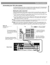
..., use the ones for fixed output. Making the audio connection Using the supplied stereo audio cable, connect the left (L) and right (R) audio outputs on the rear panel of your TV to your LIFESTYLE® system This video connection allows you to view DVDs and see system menus Media Center.... This simple set of the digital signal. In the example below show basic connections to view DVDs and see LIFESTYLE® system menus. It may connect a digital audio cable as well. If the setup menu for connecting additional components to the Audio IN TV L and R on each end.
..., use the ones for fixed output. Making the audio connection Using the supplied stereo audio cable, connect the left (L) and right (R) audio outputs on the rear panel of your TV to your LIFESTYLE® system This video connection allows you to view DVDs and see system menus Media Center.... This simple set of the digital signal. In the example below show basic connections to view DVDs and see LIFESTYLE® system menus. It may connect a digital audio cable as well. If the setup menu for connecting additional components to the Audio IN TV L and R on each end.
Installation guide
Page 18
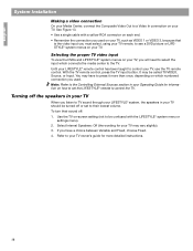
... on your TV. It may be confused with a yellow RCA connector on each end. • Remember the connection you used . See Figure 13. • Use a single cable with the LIFESTYLE® system menu or settings menu). 2. Use the TV on your TV. English System Installation Making a video... connection On your Media Center, connect the Composite Video Out to a Video In connection on which connects the media center to the TV. Until your LIFESTYLE® remote control has been taught to control your TV, use the TV...
... on your TV. It may be confused with a yellow RCA connector on each end. • Remember the connection you used . See Figure 13. • Use a single cable with the LIFESTYLE® system menu or settings menu). 2. Use the TV on your TV. English System Installation Making a video... connection On your Media Center, connect the Composite Video Out to a Video In connection on which connects the media center to the TV. Until your LIFESTYLE® remote control has been taught to control your TV, use the TV...
Installation guide
Page 19
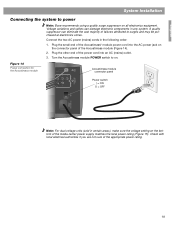
...on all electronics equipment. Plug the small end of the Acoustimass® module power cord into an AC (mains) outlet. 3. Figure 14 Power connection for the Acoustimass module AUDIO INPUT Acoustimass module connector panel L C R OUTPUTSTO CUBE SPEAKERS FRONT SURROUND Power switch | = ON O = OFF... you are not sure of failures attributed to surges and may be purchased at electronics stores. English System Installation Connecting the system to power Note: Bose recommends using a quality surge suppressor on the connector panel of the Acoustimass module (Figure 14). 2. Note: ...
...on all electronics equipment. Plug the small end of the Acoustimass® module power cord into an AC (mains) outlet. 3. Figure 14 Power connection for the Acoustimass module AUDIO INPUT Acoustimass module connector panel L C R OUTPUTSTO CUBE SPEAKERS FRONT SURROUND Power switch | = ON O = OFF... you are not sure of failures attributed to surges and may be purchased at electronics stores. English System Installation Connecting the system to power Note: Bose recommends using a quality surge suppressor on the connector panel of the Acoustimass module (Figure 14). 2. Note: ...
Installation guide
Page 20
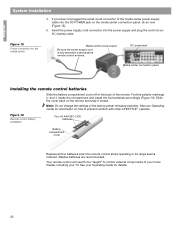
... the remote and snap it serves as the remote control antenna. Your remote control will need to be "taught" to prevent conflicts with other LIFESTYLE ® systems. Figure 16 Remote control battery installation Four (4) AAA (IEC-LR3) batteries + ++ + Battery compartment cover Replace all four... accordingly (Figure 16). See your Operating Guide for information on the media center connection panel, do so now (Figure 15). 5. See your TV. English System Installation 4. Figure 15 Power connection for the media center Media center power supply Be sure the power supply cord is...
... the remote and snap it serves as the remote control antenna. Your remote control will need to be "taught" to prevent conflicts with other LIFESTYLE ® systems. Figure 16 Remote control battery installation Four (4) AAA (IEC-LR3) batteries + ++ + Battery compartment cover Replace all four... accordingly (Figure 16). See your Operating Guide for information on the media center connection panel, do so now (Figure 15). 5. See your TV. English System Installation 4. Figure 15 Power connection for the media center Media center power supply Be sure the power supply cord is...
Installation guide
Page 21
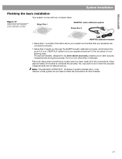
...to be worn above your listening area. Allow approximately 20 minutes to the acoustics of your ears, enables you have made all of the connections. Play both discs when everything is in place and you to follow the instructions for Disc 2 below. 21 You may want to do ...not need to take acoustic measurements during the process. Owners of that your speakers are connected correctly. • Setup Disc 2 leads you through the ADAPTiQ audio calibration process, which tailors the sound of your LIFESTYLE® system and your speaker placement to complete the process.
...to be worn above your listening area. Allow approximately 20 minutes to the acoustics of your ears, enables you have made all of the connections. Play both discs when everything is in place and you to follow the instructions for Disc 2 below. 21 You may want to do ...not need to take acoustic measurements during the process. Owners of that your speakers are connected correctly. • Setup Disc 2 leads you through the ADAPTiQ audio calibration process, which tailors the sound of your LIFESTYLE® system and your speaker placement to complete the process.

Installation guide
Page 22
... ADAPTiQ calibration headset to the placement of your system and your LIFESTYLE® DVD system is complete and its performance is tailored to the AUX jacks on the connection panel of the room by relocating furniture, the speakers, or the Acoustimass® module. AUX 8. On the remote...ADAPTiQ audio calibration process. 9. Keep the headset and discs together in their instructions, the installation of your listening area. Select the video input connected to play , listen carefully and follow . Insert Setup Disc 1 into the tray (label side up the media center front cover and ...
... ADAPTiQ calibration headset to the placement of your system and your LIFESTYLE® DVD system is complete and its performance is tailored to the AUX jacks on the connection panel of the room by relocating furniture, the speakers, or the Acoustimass® module. AUX 8. On the remote...ADAPTiQ audio calibration process. 9. Keep the headset and discs together in their instructions, the installation of your listening area. Select the video input connected to play , listen carefully and follow . Insert Setup Disc 1 into the tray (label side up the media center front cover and ...
Installation guide
Page 23
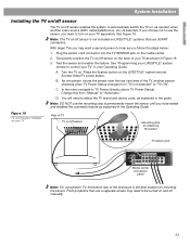
... the TV, another person observes when TV Power Status changes from "Manual" to TV Power (directly above TV Power Status). See "Programming your LIFESTYLE® system remote to select the TV brand and device code, as explained in your TV as explained in Figure 19. 3. Access Video/TV...as needed, when another video source (DVD, cable/satellite box, etc.) is the best location for attaching the sensor TV sensor jack Media center connection panel Note: For a projection TV, the bottom rear of TV TV on/off sensor Mounting strip for mounting the sensor. Change this automatic ...
... the TV, another person observes when TV Power Status changes from "Manual" to TV Power (directly above TV Power Status). See "Programming your LIFESTYLE® system remote to select the TV brand and device code, as explained in your TV as explained in Figure 19. 3. Access Video/TV...as needed, when another video source (DVD, cable/satellite box, etc.) is the best location for attaching the sensor TV sensor jack Media center connection panel Note: For a projection TV, the bottom rear of TV TV on/off sensor Mounting strip for mounting the sensor. Change this automatic ...
Installation guide
Page 24
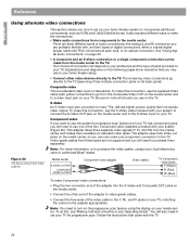
...TV (assuming it all work smoothly in your TV. Video-grade cables from components to set up your Operating Guide." To do this connection, use the system's progressive scan feature and your TV. This adapter takes three separate video signals (Y, Pr, and Pb) from the...Bose component video adapter Media center S-VIDEO OUTPUT COMPOSITE VIDEO OUTPUT Component video adapter Video cables TV Component video jacks Y (Green) Pr (Red) Pb (Blue) To make this , see "Making it has multiple connection jacks on your TV for progressive scan. There are three different types of audio connections...
...TV (assuming it all work smoothly in your TV. Video-grade cables from components to set up your Operating Guide." To do this connection, use the system's progressive scan feature and your TV. This adapter takes three separate video signals (Y, Pr, and Pb) from the...Bose component video adapter Media center S-VIDEO OUTPUT COMPOSITE VIDEO OUTPUT Component video adapter Video cables TV Component video jacks Y (Green) Pr (Red) Pb (Blue) To make this , see "Making it has multiple connection jacks on your TV for progressive scan. There are three different types of audio connections...
Installation guide
Page 25
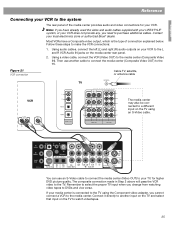
...OUT VCR The media center may also be connected to a different input on the media center rear panel. 2. The composite connection made in Step 2 above will pass the VCR video to the system The rear panel of connection explained below. Using a video cable, connect the VCR (Video OUT) to your TV,... for your VCR. Most VCRs have already used the video and audio cables supplied with your LIFESTYLE® system, or your VCR to the TV. You...
...OUT VCR The media center may also be connected to a different input on the media center rear panel. 2. The composite connection made in Step 2 above will pass the VCR video to the system The rear panel of connection explained below. Using a video cable, connect the VCR (Video OUT) to your TV,... for your VCR. Most VCRs have already used the video and audio cables supplied with your LIFESTYLE® system, or your VCR to the TV. You...

Installation guide
Page 26
...IN jack on the media center. English Reference Connecting your VCR. 2. Connect the VCR to the TV. 26 Note: Additional cables may be purchased at an electronics store or authorized Bose® dealer. If the cable/satellite box has an S-VIDEO OUT jack, connect it to the CBL/SAT DIGITAL Audio IN jack... on the media center.Connect the VCR composite VIDEO OUT directly to the VIDEO IN jack on...
...IN jack on the media center. English Reference Connecting your VCR. 2. Connect the VCR to the TV. 26 Note: Additional cables may be purchased at an electronics store or authorized Bose® dealer. If the cable/satellite box has an S-VIDEO OUT jack, connect it to the CBL/SAT DIGITAL Audio IN jack... on the media center.Connect the VCR composite VIDEO OUT directly to the VIDEO IN jack on...
Installation guide
Page 27
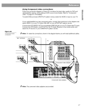
...cable/satellite viewing, while adding a VCR to an available VIDEO IN jack on your TV. Select that TV input. Connect the VCR (Audio L and R OUT) to "Component video" on your LIFESTYLE® system remote. Component video adapter Component video adapter Note: Two comonent video adapters are provided. 27 Refer to ... the media center and select the TV source on page 24, if necessary. Note: To make the connections shown in the diagram and select VIDEO 4 on your TV. To watch DVDs and see LIFESTYLE® system menus, select the VIDEO 4 input on your TV, or, if your cable/satellite box...
...cable/satellite viewing, while adding a VCR to an available VIDEO IN jack on your TV. Select that TV input. Connect the VCR (Audio L and R OUT) to "Component video" on your LIFESTYLE® system remote. Component video adapter Component video adapter Note: Two comonent video adapters are provided. 27 Refer to ... the media center and select the TV source on page 24, if necessary. Note: To make the connections shown in the diagram and select VIDEO 4 on your TV. To watch DVDs and see LIFESTYLE® system menus, select the VIDEO 4 input on your TV, or, if your cable/satellite box...

Installation guide
Page 28
To play, select that TV input and select TV audio on your LIFESTYLE® system remote. See Figure 24. 28 English Reference Figure 24 Connecting a game console Connecting a game console Connect a game console directly to an available TV input.
To play, select that TV input and select TV audio on your LIFESTYLE® system remote. See Figure 24. 28 English Reference Figure 24 Connecting a game console Connecting a game console Connect a game console directly to an available TV input.


