The Bose® Lifestyle® amplifier - Owner's guide
Page 6
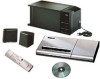
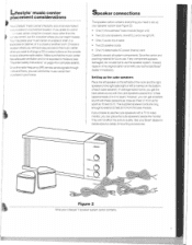
...er. Note: Locate the serial number on the bottom panel of the shipping carton 30-ft audio input cable PN197406 Lifestyle® stereo amplifier Owner's guide Power cord* USA/Canada (120V) * The Lifestyle® stereo amplifier includes a 120V AC (mains) power cord for use in ... UK/Singapore (230V) Australia (240V) plug adaptor Note: Use only the power cord supplied with a simple solution when you can enjoy Bose quality sound and Lifestyle® system convenience in the amplifier, ensures full, rich stereo sound, even when the speakers are playing at low volumes. ...
...er. Note: Locate the serial number on the bottom panel of the shipping carton 30-ft audio input cable PN197406 Lifestyle® stereo amplifier Owner's guide Power cord* USA/Canada (120V) * The Lifestyle® stereo amplifier includes a 120V AC (mains) power cord for use in ... UK/Singapore (230V) Australia (240V) plug adaptor Note: Use only the power cord supplied with a simple solution when you can enjoy Bose quality sound and Lifestyle® system convenience in the amplifier, ensures full, rich stereo sound, even when the speakers are playing at low volumes. ...
The Bose® Lifestyle® amplifier - Owner's guide
Page 7
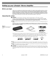
...for your Lifestyle® stereo amplifier and mount it according to limit its temperature. • DO NOT place the amplifier on surfaces that are not sturdy enough, or that the amplifier is located within the reach of the supplied 30-foot audio input ... a wall (Figure 4), remove the rubber feet and use outdoors or on page 6 for recommended mounting hardware. Setting Up Your Lifestyle® Stereo Amplifier Selecting a location for your Lifestyle® stereo amplifier Select a location for your amplifier: • Locate the amplifier indoors and...
...for your Lifestyle® stereo amplifier and mount it according to limit its temperature. • DO NOT place the amplifier on surfaces that are not sturdy enough, or that the amplifier is located within the reach of the supplied 30-foot audio input ... a wall (Figure 4), remove the rubber feet and use outdoors or on page 6 for recommended mounting hardware. Setting Up Your Lifestyle® Stereo Amplifier Selecting a location for your Lifestyle® stereo amplifier Select a location for your amplifier: • Locate the amplifier indoors and...
The Bose® Lifestyle® amplifier - Owner's guide
Page 9
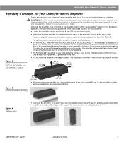
... cable into the L (left) INPUT jack. At the other connections. 1. Figure 6 Cable connections between a multi-room interface and the Lifestyle® stereo amplifier Lifestyle® stereo amplifier rear panel Multi-room interface rear panel 4 Ω MINIMUM LL R L SYSTEM RR CONTROL L R +-...multi-room interface CAUTION: Before making any connections, turn the Lifestyle® system off and disconnect the music center from the AC (mains) power outlet. Insert the single multi-pin connector at one end of the audio input cable into the R (right) INPUT jack of the...
... cable into the L (left) INPUT jack. At the other connections. 1. Figure 6 Cable connections between a multi-room interface and the Lifestyle® stereo amplifier Lifestyle® stereo amplifier rear panel Multi-room interface rear panel 4 Ω MINIMUM LL R L SYSTEM RR CONTROL L R +-...multi-room interface CAUTION: Before making any connections, turn the Lifestyle® system off and disconnect the music center from the AC (mains) power outlet. Insert the single multi-pin connector at one end of the audio input cable into the R (right) INPUT jack of the...
The Bose® Lifestyle® amplifier - Owner's guide
Page 11
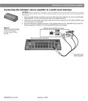
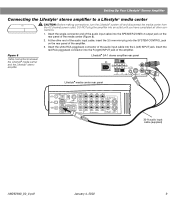
... the amplifier. 3. At the other connections. 1. Figure 8 Cable connections between the Lifestyle® media center and the Lifestyle® stereo amplifier Lifestyle® SA-1 stereo amplifier rear panel Lifestyle® media center rear panel 30-ft audio input cable (supplied) AM262840_00_V.pdf January 4, 2002 9 Insert the red RCA piggyback connector into...
... the amplifier. 3. At the other connections. 1. Figure 8 Cable connections between the Lifestyle® media center and the Lifestyle® stereo amplifier Lifestyle® SA-1 stereo amplifier rear panel Lifestyle® media center rear panel 30-ft audio input cable (supplied) AM262840_00_V.pdf January 4, 2002 9 Insert the red RCA piggyback connector into...
The Bose® Lifestyle® amplifier - Owner's guide
Page 13
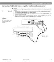
... INPUT Model 20 music center rear panel 30-ft audio input cable (supplied) AM262840_00_V.pdf January 4, 2002 11 Insert the white RCA piggyback connector of the supplied cable into the SYSTEM CONTROL jack on the rear panel of the amplifier. Lifestyle® stereo amplifier rear panel 4 &#..., turn the Lifestyle® system off and disconnect the music center from the AC (mains) power outlet. DO NOT plug the amplifier into the R (right) INPUT jack of the music center (Figure 10). 2. Insert the single multi-pin connector at one end of the audio input cable into...
... INPUT Model 20 music center rear panel 30-ft audio input cable (supplied) AM262840_00_V.pdf January 4, 2002 11 Insert the white RCA piggyback connector of the supplied cable into the SYSTEM CONTROL jack on the rear panel of the amplifier. Lifestyle® stereo amplifier rear panel 4 &#..., turn the Lifestyle® system off and disconnect the music center from the AC (mains) power outlet. DO NOT plug the amplifier into the R (right) INPUT jack of the music center (Figure 10). 2. Insert the single multi-pin connector at one end of the audio input cable into...
The Bose® Lifestyle® amplifier - Owner's guide
Page 15
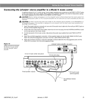
...2 ~ POWER 12VAC IN 1.0A ANTENNA SEE INSTRUCTION MANUAL Fixed speaker outputs 30-ft audio input cable (supplied) Acoustimass module cable AM262840_00_V.pdf January 4, 2002 13 Setting Up Your Lifestyle® Stereo Amplifier Connecting the Lifestyle® stereo amplifier to a Model 5 music center In systems using ...mm mini-plug into the SYSTEM CONTROL 2 jack on the rear of the audio input cable into the L (left) FIXED OUTPUT jack. 5. CAUTION: DO NOT connect the audio input cable for the Lifestyle® stereo amplifier to work properly with the fixed output...
...2 ~ POWER 12VAC IN 1.0A ANTENNA SEE INSTRUCTION MANUAL Fixed speaker outputs 30-ft audio input cable (supplied) Acoustimass module cable AM262840_00_V.pdf January 4, 2002 13 Setting Up Your Lifestyle® Stereo Amplifier Connecting the Lifestyle® stereo amplifier to a Model 5 music center In systems using ...mm mini-plug into the SYSTEM CONTROL 2 jack on the rear of the audio input cable into the L (left) FIXED OUTPUT jack. 5. CAUTION: DO NOT connect the audio input cable for the Lifestyle® stereo amplifier to work properly with the fixed output...

The Bose® Lifestyle® amplifier - Owner's guide
Page 18
... for service, or contact Bose Customer Service. For additional help, see the troubleshooting information in and turned on the audio input cable.) • Disconnect any openings. Troubleshooting If you do Neither speaker plays • Make sure the Lifestyle® music center and ...may use caulking, apply it only after installing the Lifestyle® stereo amplifier, follow the guidelines below. It is designed only for home theater (Lifestyle® 12 or Lifestyle® 8 systems), make sure the audio input cable is inserted into any headphones. •...
... for service, or contact Bose Customer Service. For additional help, see the troubleshooting information in and turned on the audio input cable.) • Disconnect any openings. Troubleshooting If you do Neither speaker plays • Make sure the Lifestyle® music center and ...may use caulking, apply it only after installing the Lifestyle® stereo amplifier, follow the guidelines below. It is designed only for home theater (Lifestyle® 12 or Lifestyle® 8 systems), make sure the audio input cable is inserted into any headphones. •...
The Bose® Lifestyle® amplifier - Owner's guide
Page 20
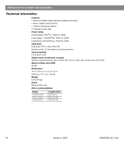
W x 51/2 in . Maintaining Your Lifestyle® Stereo Amplifier Technical information Features • Bose® proprietary digital signal processing technology • Built-in digital volume control • Thermal overload protection • Protective rubber ...feet Power rating USA/Canada: 120V 50/60 Hz, 220W Dual voltage: 115/230V 50/60 Hz, 220W International: 220-240V 50/60 Hz, 220W Input jacks Dual audio...
W x 51/2 in . Maintaining Your Lifestyle® Stereo Amplifier Technical information Features • Bose® proprietary digital signal processing technology • Built-in digital volume control • Thermal overload protection • Protective rubber ...feet Power rating USA/Canada: 120V 50/60 Hz, 220W Dual voltage: 115/230V 50/60 Hz, 220W International: 220-240V 50/60 Hz, 220W Input jacks Dual audio...
Owner's guide
Page 7
...and the right speaker on the right side (right or left (L)and oneright (R) • One (1) audio input cable • Two (2) speaker cords • One (1) detachable AC power (mains) cord ...Important safety instructions' on the bottom of mounting accessories. ..&11026e- • Figure 2 What your Lifestyle' 3 speaker system carton contains. If you choose to control music center using the consoles keys rather...remote control, put it easily. If you prefer to use . Youmay place your Bose' dealer for complete details). Since theradio-frequency(RF) remote sends signals through walls and...
...and the right speaker on the right side (right or left (L)and oneright (R) • One (1) audio input cable • Two (2) speaker cords • One (1) detachable AC power (mains) cord ...Important safety instructions' on the bottom of mounting accessories. ..&11026e- • Figure 2 What your Lifestyle' 3 speaker system carton contains. If you choose to control music center using the consoles keys rather...remote control, put it easily. If you prefer to use . Youmay place your Bose' dealer for complete details). Since theradio-frequency(RF) remote sends signals through walls and...

Owner's guide
Page 9
... connect positive to positive and negative to negative. 1. Connecting the cube speakers to the bass module CAUTION: Be sure allcomponents(Lifestyle' music center andthe Acouslimase bassmodule)areunpluggedfrom the power outletbeforeyoubeginhooking up the speaker system. Repeat steps 2 and 3 for the right ...The wire marked with a stripe or a red collar is more than ..-) feet (9 m) from the music center, purchase a Bose' audio out extension cable (EC-11, Bose' part no strands of the cover (see Figure 6). 3. To make the connection, push each cube speaker by alternating pressure at...
... connect positive to positive and negative to negative. 1. Connecting the cube speakers to the bass module CAUTION: Be sure allcomponents(Lifestyle' music center andthe Acouslimase bassmodule)areunpluggedfrom the power outletbeforeyoubeginhooking up the speaker system. Repeat steps 2 and 3 for the right ...The wire marked with a stripe or a red collar is more than ..-) feet (9 m) from the music center, purchase a Bose' audio out extension cable (EC-11, Bose' part no strands of the cover (see Figure 6). 3. To make the connection, push each cube speaker by alternating pressure at...

Owner's guide
Page 10
...jack. • Black connector plug into the SYSTEM CONTROL jack. Connect the other end of the audio input cable to the jacks on the back of the cable to your Lifestyle' music center. • Red connector pluginto theR(right)SPEAKERS A OUTPUT jack. • White ...illustration. 3 3.k ita Figure 7 Connections between the bass module and the music center. 10 Connecting the bass module to the Lifestyle music center (SeeFigure 7) 1. The audio input cable has three connectors at each end: red, white. Note: Ifyou haveaddedan audioinput extension cable, do notplugin this black ...
...jack. • Black connector plug into the SYSTEM CONTROL jack. Connect the other end of the audio input cable to the jacks on the back of the cable to your Lifestyle' music center. • Red connector pluginto theR(right)SPEAKERS A OUTPUT jack. • White ...illustration. 3 3.k ita Figure 7 Connections between the bass module and the music center. 10 Connecting the bass module to the Lifestyle music center (SeeFigure 7) 1. The audio input cable has three connectors at each end: red, white. Note: Ifyou haveaddedan audioinput extension cable, do notplugin this black ...

Owner's guide
Page 13
...speaker system to the corresponding positive and negative terminals on the lett and right sties of mounting accessories. but connect your Bose' dealer for Bose Lifestyle rrevered speakers Ce complete information on the other end of wire from any terminal touch any other (See Figure 10) ...or a red collar is always negative (--). The speaker carton contains: • One (1) LEFT (powered) speaker with attached power cord and audio input cable • One(1)RIGHT (accessory) speaker with speaker terminals on thebacksof the speakers. These correspond to secure the wire.
...speaker system to the corresponding positive and negative terminals on the lett and right sties of mounting accessories. but connect your Bose' dealer for Bose Lifestyle rrevered speakers Ce complete information on the other end of wire from any terminal touch any other (See Figure 10) ...or a red collar is always negative (--). The speaker carton contains: • One (1) LEFT (powered) speaker with attached power cord and audio input cable • One(1)RIGHT (accessory) speaker with speaker terminals on thebacksof the speakers. These correspond to secure the wire.

Owner's guide
Page 14
...red plug at the other end of the extension cable intotheR(right)SPEAKERSB OUTPUT jack onthe back of the left speaker for theL(left ) speaker's audio input cable into the corresponding red and black jacks on the left speaker into the SPEAKERS 8 OUTPUT jack for the correct voltage. 3. On ...dual voltage models, set the voltage selector switch on ' the back of the Lifestyle* music center. Finishing the speaker setup 1. Insert the red and black plugs from the left speaker counterclockwise to its lowest position. 2. Your...
...red plug at the other end of the extension cable intotheR(right)SPEAKERSB OUTPUT jack onthe back of the left speaker for theL(left ) speaker's audio input cable into the corresponding red and black jacks on the left speaker into the SPEAKERS 8 OUTPUT jack for the correct voltage. 3. On ...dual voltage models, set the voltage selector switch on ' the back of the Lifestyle* music center. Finishing the speaker setup 1. Insert the red and black plugs from the left speaker counterclockwise to its lowest position. 2. Your...

Owner's guide
Page 15
... CE. ® A I eNse e er e. 0 a Y •0 2 L. to 100-foot stereo cable with a Lifestyle' music system. 1f vermin.* J ( Err ''' Figure 12 Finished hookup with male-to left. 1. Insert the audio cables red plug into your lifestyle' music center'sR(right)FIXED OUTPUT jack.Insert theblack or white plug into the Wave.... 2. At the other end of the same cable, insert the red plug into theL (left to -male RCA plugs, or contact Bose Corporation directly (see "Customer Service," page 39). Insert the black or white plug into its left ). Connections for a 25- Connecting the radio...
... CE. ® A I eNse e er e. 0 a Y •0 2 L. to 100-foot stereo cable with a Lifestyle' music system. 1f vermin.* J ( Err ''' Figure 12 Finished hookup with male-to left. 1. Insert the audio cables red plug into your lifestyle' music center'sR(right)FIXED OUTPUT jack.Insert theblack or white plug into the Wave.... 2. At the other end of the same cable, insert the red plug into theL (left to -male RCA plugs, or contact Bose Corporation directly (see "Customer Service," page 39). Insert the black or white plug into its left ). Connections for a 25- Connecting the radio...

Owner's guide
Page 19
... a TV. FIXED and VARIABLE - Insert the black or white plug into the Lifestyle music center's right TAPE PLAY INPUT. Connecting other end of the same cable into the Lifestyle' music center'sR(right) TAPEREC OUTPUT. Lc r , 7 A tk..-. Insert... Figure 18). Mary manufacturers supply one end of the same cable into theright AUDIO OUTPUTof the CD player or tape deck. These cables are two sets of the same cable into the left... AUDIO OUTPUT. Insert the red plug at the other end of outputs - use the FIXED ...
... a TV. FIXED and VARIABLE - Insert the black or white plug into the Lifestyle music center's right TAPE PLAY INPUT. Connecting other end of the same cable into the Lifestyle' music center'sR(right) TAPEREC OUTPUT. Lc r , 7 A tk..-. Insert... Figure 18). Mary manufacturers supply one end of the same cable into theright AUDIO OUTPUTof the CD player or tape deck. These cables are two sets of the same cable into the left... AUDIO OUTPUT. Insert the red plug at the other end of outputs - use the FIXED ...

Owner's guide
Page 20
...VCR, Laserdisc, or other end of the same cable into theR(right)VIDEO SOUNDINPUT of your Lifestyle music center. The jack will need an external phcno preampli• eft fier.Consult your Bose dealer to the SPEAKERS 8 listening area, if speakers are connected. Insert the black or white... plug into the right AUDIO OUTPUT of your TV. Insert theblack or white pluginto the left AUDIO OUTPUT. you will accept most popular headphone models...
...VCR, Laserdisc, or other end of the same cable into theR(right)VIDEO SOUNDINPUT of your Lifestyle music center. The jack will need an external phcno preampli• eft fier.Consult your Bose dealer to the SPEAKERS 8 listening area, if speakers are connected. Insert the black or white... plug into the right AUDIO OUTPUT of your TV. Insert theblack or white pluginto the left AUDIO OUTPUT. you will accept most popular headphone models...

Owner's guide
Page 28
...'sbatteries whenitstops operatingoritsoperatingrangeseemsreduced. as indicated. it clicks into place. Then: • Check tobe surebatteries are two sets of audio outputs - Refer toFigure 25 onpage 29. Set the speaker switches in the battery compartment. Note: Ifyouarereplacingoldbatteries, lift themoutand ... SPEAKERS A and B - Youmay use , thisoccurs everyyearor two. Open the remote control's battery cover. 2. Using the standard Lifestyle' remote control Before using the deluxe remote control, match its house-code switch settings to control either SPEAKERS A or B. You ...
...'sbatteries whenitstops operatingoritsoperatingrangeseemsreduced. as indicated. it clicks into place. Then: • Check tobe surebatteries are two sets of audio outputs - Refer toFigure 25 onpage 29. Set the speaker switches in the battery compartment. Note: Ifyouarereplacingoldbatteries, lift themoutand ... SPEAKERS A and B - Youmay use , thisoccurs everyyearor two. Open the remote control's battery cover. 2. Using the standard Lifestyle' remote control Before using the deluxe remote control, match its house-code switch settings to control either SPEAKERS A or B. You ...

Owner's guide
Page 33
...Figure 27 Youcanaim yourCE-1ControlExpander unit directly at the comps•- 'ou want to their cables allow. or 8-foot (2 or 2.5 m) audio cables. Referto 14'hen touse theinfraredextension cable,"page 34. If youplace your unit farther from your CD changer and tape deck. furniture, and ...'s owner's manual, your CD changer and tape deck. Note: BeforeyousetupyourCE-1ControlExpanderunit, follow theinstructions onpages 19-20 to the Lifestyles music center. place the CE Contra Expander unit within easy reach. Choosing a convenient location Place your CD changer and tape...
...Figure 27 Youcanaim yourCE-1ControlExpander unit directly at the comps•- 'ou want to their cables allow. or 8-foot (2 or 2.5 m) audio cables. Referto 14'hen touse theinfraredextension cable,"page 34. If youplace your unit farther from your CD changer and tape deck. furniture, and ...'s owner's manual, your CD changer and tape deck. Note: BeforeyousetupyourCE-1ControlExpanderunit, follow theinstructions onpages 19-20 to the Lifestyles music center. place the CE Contra Expander unit within easy reach. Choosing a convenient location Place your CD changer and tape...

Owner's guide
Page 41
TAPE HeadP• rte: 320 minimum impedance SYS CONTROL: for use with Bose' powered speakers and accessories Remote control range Dimensions Music center 15'Wx9"Dx2.51-1 (38 cm x 23 cm x6 cm) Cube speakers 4.5'W x 3.5'0 x 4.51H (11 cmx9cmx ... Music center inputs TAPE: 3Vmaximum AUX, VIDEO-SOUND: av maximum FM antenna: 750 AM a 12!in RDA... )2V -AC, 1.0 A Outputs Venable audo: SPEAKERS A and B Fixed audio: FIXED.
TAPE HeadP• rte: 320 minimum impedance SYS CONTROL: for use with Bose' powered speakers and accessories Remote control range Dimensions Music center 15'Wx9"Dx2.51-1 (38 cm x 23 cm x6 cm) Cube speakers 4.5'W x 3.5'0 x 4.51H (11 cmx9cmx ... Music center inputs TAPE: 3Vmaximum AUX, VIDEO-SOUND: av maximum FM antenna: 750 AM a 12!in RDA... )2V -AC, 1.0 A Outputs Venable audo: SPEAKERS A and B Fixed audio: FIXED.


