The Bose® Lifestyle® amplifier - Owner's guide
Page 5
... a Model 20 music center 11 Connecting the Lifestyle® stereo amplifier to a Model 5 music center 13 Connecting speakers to your Lifestyle® stereo amplifier 14 Checking to a Lifestyle® media center 9 Setting up your system 15 Maintaining Your Lifestyle® Stereo Amplifier Cleaning the amplifier 16 Protecting outdoor wiring 16 Troubleshooting 16 Customer service 17 Warranty...
... a Model 20 music center 11 Connecting the Lifestyle® stereo amplifier to a Model 5 music center 13 Connecting speakers to your Lifestyle® stereo amplifier 14 Checking to a Lifestyle® media center 9 Setting up your system 15 Maintaining Your Lifestyle® Stereo Amplifier Cleaning the amplifier 16 Protecting outdoor wiring 16 Troubleshooting 16 Customer service 17 Warranty...
The Bose® Lifestyle® amplifier - Owner's guide
Page 7
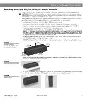
...allow for air flow. Figure 2 Required clearance between the amplifier and any heat-sensitive surface, such as electrical wiring or plumbing. It is neither designed nor tested for recommended mounting hardware. Although the amplifier does not need to be ...placed indoors. AM262840_00_V.pdf January 4, 2002 5 The amplifier must be situated close to either your Lifestyle® system or the accessory speakers, consider the following guidelines. If adequate ventilation is not provided, the amplifier will automatically protect itself by reducing...
...allow for air flow. Figure 2 Required clearance between the amplifier and any heat-sensitive surface, such as electrical wiring or plumbing. It is neither designed nor tested for recommended mounting hardware. Although the amplifier does not need to be ...placed indoors. AM262840_00_V.pdf January 4, 2002 5 The amplifier must be situated close to either your Lifestyle® system or the accessory speakers, consider the following guidelines. If adequate ventilation is not provided, the amplifier will automatically protect itself by reducing...
The Bose® Lifestyle® amplifier - Owner's guide
Page 16
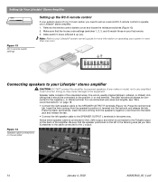
... way. Note: Refer to your Lifestyle® system owner's guide for more than one room. For recommended wire sizes and lengths, see "Wire recommendations" on the amplifier 14 January 4, 2002 AM262840_00_V.pdf Insert the wire coming from the speaker's negative (-) terminal into the red...match those in the listening area (as you need to set up a second RC-5 remote control to operate your Lifestyle® stereo amplifier. 1. Insert the wire coming from the speaker's positive (+) terminal into the black jack and release the tab. • Connect the left ) output, and ...
... way. Note: Refer to your Lifestyle® system owner's guide for more than one room. For recommended wire sizes and lengths, see "Wire recommendations" on the amplifier 14 January 4, 2002 AM262840_00_V.pdf Insert the wire coming from the speaker's negative (-) terminal into the red...match those in the listening area (as you need to set up a second RC-5 remote control to operate your Lifestyle® stereo amplifier. 1. Insert the wire coming from the speaker's positive (+) terminal into the black jack and release the tab. • Connect the left ) output, and ...

The Bose® Lifestyle® amplifier - Owner's guide
Page 18
...You may become dusty over time. If the problem still exists, contact your Lifestyle® stereo amplifier" on page 14. 16 January 4, 2002 AM262840_00_V.pdf Protecting outdoor wiring Although some Bose® speakers are firmly connected at hardware stores. For additional help, see the ...to outdoor weather conditions, the bare ends of the speaker wire can be affected by exposure to AUX is turned on. • If using a Model 5 music center for indoor use caulking, apply it only after installing the Lifestyle® stereo amplifier, follow the guidelines ...
...You may become dusty over time. If the problem still exists, contact your Lifestyle® stereo amplifier" on page 14. 16 January 4, 2002 AM262840_00_V.pdf Protecting outdoor wiring Although some Bose® speakers are firmly connected at hardware stores. For additional help, see the ...to outdoor weather conditions, the bare ends of the speaker wire can be affected by exposure to AUX is turned on. • If using a Model 5 music center for indoor use caulking, apply it only after installing the Lifestyle® stereo amplifier, follow the guidelines ...
The Bose® Lifestyle® amplifier - Owner's guide
Page 19
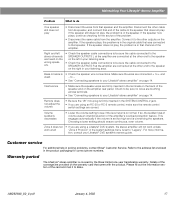
...;er" on the warranty card that speaker and the amplifier. Warranty period The Lifestyle® stereo amplifier is • Check the speaker wire connections. Right and left stereo channels are heard on the wrong speakers. • Check the speaker cable connections to be sure the cable... in the product packaging for the source of the speaker and on the right in the original cable that was an intentional action of the cable to the speaker that speaker. Bass or treble is covered by the Bose limited one-year transferable warranty. tion, consult your ...
...;er" on the warranty card that speaker and the amplifier. Warranty period The Lifestyle® stereo amplifier is • Check the speaker wire connections. Right and left stereo channels are heard on the wrong speakers. • Check the speaker cable connections to be sure the cable... in the product packaging for the source of the speaker and on the right in the original cable that was an intentional action of the cable to the speaker that speaker. Bass or treble is covered by the Bose limited one-year transferable warranty. tion, consult your ...
Owner's guide
Page 42
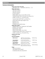
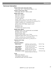
...to input FM antenna: 75 Ω AM antenna: 12µH TV SENSOR: Scan frequency sensing Media center outputs SPEAKER ZONES 1 and 2: Variable audio, user selectable RECORD L and R: Fixed audio RECORD DIGITAL: SPDIF OPTICAL OUTPUT: ...65 ft (20m) Dimensions/Weights Media Center: 15.8" W x 11.0" D x 3.5" H (40.1 cm x 27.9 cm x 8.9 cm) 8.2 lb (3.7 kg) Cube speakers: (2-wire conn.) 3.1" W x 4.0" D x 6.2" H (7.8 cm x 10.2 cm x 15.7 cm) 2.4 lb (1.1 kg) Cube speakers: (plug-in conn.) 2.2" W x 3.2" D x 4.4" H (5.6 cm x 8.1 cm x 11.2 cm) 1.0 lb (0.5 kg) Acoustimass module: 8.0" W x 24.5" ...
...to input FM antenna: 75 Ω AM antenna: 12µH TV SENSOR: Scan frequency sensing Media center outputs SPEAKER ZONES 1 and 2: Variable audio, user selectable RECORD L and R: Fixed audio RECORD DIGITAL: SPDIF OPTICAL OUTPUT: ...65 ft (20m) Dimensions/Weights Media Center: 15.8" W x 11.0" D x 3.5" H (40.1 cm x 27.9 cm x 8.9 cm) 8.2 lb (3.7 kg) Cube speakers: (2-wire conn.) 3.1" W x 4.0" D x 6.2" H (7.8 cm x 10.2 cm x 15.7 cm) 2.4 lb (1.1 kg) Cube speakers: (plug-in conn.) 2.2" W x 3.2" D x 4.4" H (5.6 cm x 8.1 cm x 11.2 cm) 1.0 lb (0.5 kg) Acoustimass module: 8.0" W x 24.5" ...
Installation guide
Page 3
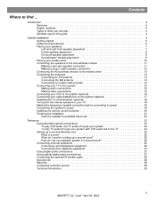
...speakers 7 Left and right front speaker placement 7 Center speaker placement 8 Surround speaker placement 8 Acoustimass® module placement 9 Placing your media center 10 Connecting the speakers to the Acoustimass module 11 Making a two-wire speaker connection 11 Making a plug-in cable speaker...the TV on/off detector (optional 18 Turning off the internal speakers in your TV 18 Making the temporary headset connection before connecting to... for setting up a second zone 25 How do I set up a speaker system in a second zone 25 Connecting external equipment 26 Connecting record/playback...
...speakers 7 Left and right front speaker placement 7 Center speaker placement 8 Surround speaker placement 8 Acoustimass® module placement 9 Placing your media center 10 Connecting the speakers to the Acoustimass module 11 Making a two-wire speaker connection 11 Making a plug-in cable speaker...the TV on/off detector (optional 18 Turning off the internal speakers in your TV 18 Making the temporary headset connection before connecting to... for setting up a second zone 25 How do I set up a speaker system in a second zone 25 Connecting external equipment 26 Connecting record/playback...
Installation guide
Page 11
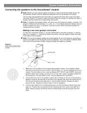
... connectors into the matching left ), R (right), or C (center) molded into the connectors. Front speaker cables have blue connectors at one speaker cable to secure the wire. Refer to the Bose address list included with your system will either have orange connectors at one end, with a red collar ...your dealer or electronics store, or call Bose® customer service. To run the cables in different directions from the Acoustimass module, simply pull apart the cables as needed. Press the terminal tab on page 12). Surround speaker cables have a two-wire cable connector (Figure 7) or a ...
... connectors into the matching left ), R (right), or C (center) molded into the connectors. Front speaker cables have blue connectors at one speaker cable to secure the wire. Refer to the Bose address list included with your system will either have orange connectors at one end, with a red collar ...your dealer or electronics store, or call Bose® customer service. To run the cables in different directions from the Acoustimass module, simply pull apart the cables as needed. Press the terminal tab on page 12). Surround speaker cables have a two-wire cable connector (Figure 7) or a ...

Installation guide
Page 12
... or R (right) molded into both the RCA connectors and the speaker connectors at the top of each cable fully into the jack on the Acoustimass® module (Figure 9). Front speakers Left Center Right Surround speakers Left Right To FRONT L To FRONT C To FRONT R To SURROUND... A plug-in cable type speaker Making a plug-in cable speaker connection In a plug-in cable connection (Figure 8), the positive and negative wires are oriented to ensure proper polarity. 3 Figure 9 Speaker connections to the corresponding speaker location. Insert the speaker connector of each of the ...
... or R (right) molded into both the RCA connectors and the speaker connectors at the top of each cable fully into the jack on the Acoustimass® module (Figure 9). Front speakers Left Center Right Surround speakers Left Right To FRONT L To FRONT C To FRONT R To SURROUND... A plug-in cable type speaker Making a plug-in cable speaker connection In a plug-in cable connection (Figure 8), the positive and negative wires are oriented to ensure proper polarity. 3 Figure 9 Speaker connections to the corresponding speaker location. Insert the speaker connector of each of the ...

Installation guide
Page 14
... SENSOR IR EMITTER SERIAL DATA 33V DC POWER 1.1A RECORD TAPE AUX VCR TV AM L L L L L FM 75 ANTENNA 1 OPTICAL OPTICAL R R R R R VIDEO INPUTS COMPOSITE S-VIDEO 2 SPEAKER ZONES INPUT OUTPUT DIGITAL AUDIO OUTPUTS DIGITAL DIGITAL DIGITAL AUDIO INPUTS DIGITAL COMPOSITE S-VIDEO VIDEO OUTPUTS Connecting an FM antenna Plug the connector on the... connection is received by the media center. Spread out the antenna arms. Change the orientation of the antenna arms to unwrap the bundled antenna wires and straighten them as much as possible. Note: Outdoor antennas may be used.
... SENSOR IR EMITTER SERIAL DATA 33V DC POWER 1.1A RECORD TAPE AUX VCR TV AM L L L L L FM 75 ANTENNA 1 OPTICAL OPTICAL R R R R R VIDEO INPUTS COMPOSITE S-VIDEO 2 SPEAKER ZONES INPUT OUTPUT DIGITAL AUDIO OUTPUTS DIGITAL DIGITAL DIGITAL AUDIO INPUTS DIGITAL COMPOSITE S-VIDEO VIDEO OUTPUTS Connecting an FM antenna Plug the connector on the... connection is received by the media center. Spread out the antenna arms. Change the orientation of the antenna arms to unwrap the bundled antenna wires and straighten them as much as possible. Note: Outdoor antennas may be used.
Installation guide
Page 29
... to input FM antenna: 75 Ω AM antenna: 12µH TV SENSOR: Scan frequency sensing Media center outputs SPEAKER ZONES 1 and 2: Variable audio, user selectable RECORD L and R: Fixed audio RECORD DIGITAL: SPDIF OPTICAL OUTPUT: SPDIF...sync on Y Remote control range 65 ft (20 m) Dimensions/Weights Media Center: 15.8" W x 11.0" D x 3.5" H (40.1 cm x 27.9 cm x 8.9 cm) Cube speakers: (2-wire conn.) 3.1" W x 4.0" D x 6.2" H (7.8 cm x 10.2 cm x 15.7 cm) Cube speakers: (plug-in conn.) 2.2" W x 3.2" D x 4.4" H (5.6 cm x 8.1 cm x 11.2 cm) Acoustimass® module: 8.0" W x 24.5" D x 16.0" H...
... to input FM antenna: 75 Ω AM antenna: 12µH TV SENSOR: Scan frequency sensing Media center outputs SPEAKER ZONES 1 and 2: Variable audio, user selectable RECORD L and R: Fixed audio RECORD DIGITAL: SPDIF OPTICAL OUTPUT: SPDIF...sync on Y Remote control range 65 ft (20 m) Dimensions/Weights Media Center: 15.8" W x 11.0" D x 3.5" H (40.1 cm x 27.9 cm x 8.9 cm) Cube speakers: (2-wire conn.) 3.1" W x 4.0" D x 6.2" H (7.8 cm x 10.2 cm x 15.7 cm) Cube speakers: (plug-in conn.) 2.2" W x 3.2" D x 4.4" H (5.6 cm x 8.1 cm x 11.2 cm) Acoustimass® module: 8.0" W x 24.5" D x 16.0" H...


