Owner's guide
Page 8
...does not require a comb filter to the type of a title. A video interface standard that sends/receives commands on 12-cm optical discs. Often referred to video with black borders at the top and bottom of the digital audio signal used for both the American Black...PAL - S-video - A component analog video signal containing one of music on a four-pin mini-DIN connector. Most televisions do not have S-video inputs. A single video signal that developed both CD and laserdisc. IR - An acronym for National Television System Committee. It is the form of the ...
...does not require a comb filter to the type of a title. A video interface standard that sends/receives commands on 12-cm optical discs. Often referred to video with black borders at the top and bottom of the digital audio signal used for both the American Black...PAL - S-video - A component analog video signal containing one of music on a four-pin mini-DIN connector. Most televisions do not have S-video inputs. A single video signal that developed both CD and laserdisc. IR - An acronym for National Television System Committee. It is the form of the ...
Owner's guide
Page 32
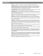
... 1 2 3 4 5 6 7 8 9 Previous 0 PLAYBACK Stop Pause Play Shuffle Repeat Speakers 2-3-5 AUDIO Surround -+ Settings Settings (source) System Setup Enter System Setup Display Brightness Display Language DVD Setup Optical Source Optical Input Record Out Format TV Power Remote Control Setup Send IR Commands Receive IR Commands Tuner Spacing Video Format Video Black Level Video Output Zone 1 Protocol...
... 1 2 3 4 5 6 7 8 9 Previous 0 PLAYBACK Stop Pause Play Shuffle Repeat Speakers 2-3-5 AUDIO Surround -+ Settings Settings (source) System Setup Enter System Setup Display Brightness Display Language DVD Setup Optical Source Optical Input Record Out Format TV Power Remote Control Setup Send IR Commands Receive IR Commands Tuner Spacing Video Format Video Black Level Video Output Zone 1 Protocol...
Owner's guide
Page 33
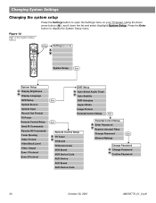
... that came with your TV separately. Not used in the selected language. This setting may be useful to teach LIFESTYLE® remote commands to match the input from external equipment are not received by your TV, VCR and AUX components. Extended Sets a black level that ...may be preferred for other Bose powered speaker systems. AM259776_01_V.pdf October 30, 2001 31 English Presents on the RECORD DIGITAL OUTPUT. Original PCM No processing applied for this system. TV / AUX / Assigns the OPTICAL INPUT to the USA standard. On Your system sends IR...
... that came with your TV separately. Not used in the selected language. This setting may be useful to teach LIFESTYLE® remote commands to match the input from external equipment are not received by your TV, VCR and AUX components. Extended Sets a black level that ...may be preferred for other Bose powered speaker systems. AM259776_01_V.pdf October 30, 2001 31 English Presents on the RECORD DIGITAL OUTPUT. Original PCM No processing applied for this system. TV / AUX / Assigns the OPTICAL INPUT to the USA standard. On Your system sends IR...
Owner's guide
Page 42
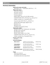
...1Vp-p with sync 75 Ω S-VIDEO: Luminance 1Vp-p, Chrominance 0.3Vp-p Component video: NTSC or PAL 1Vp-p with sync on Y OPTICAL INPUT: SPDIF digital, mapped to input FM antenna: 75 Ω AM antenna: 12µH TV SENSOR: Scan frequency sensing Media center outputs SPEAKER ZONES 1 and 2: ...Variable audio, user selectable RECORD L and R: Fixed audio RECORD DIGITAL: SPDIF OPTICAL OUTPUT: SPDIF, -15 to -21 dbm COMPOSITE VIDEO: NTSC or...
...1Vp-p with sync 75 Ω S-VIDEO: Luminance 1Vp-p, Chrominance 0.3Vp-p Component video: NTSC or PAL 1Vp-p with sync on Y OPTICAL INPUT: SPDIF digital, mapped to input FM antenna: 75 Ω AM antenna: 12µH TV SENSOR: Scan frequency sensing Media center outputs SPEAKER ZONES 1 and 2: ...Variable audio, user selectable RECORD L and R: Fixed audio RECORD DIGITAL: SPDIF OPTICAL OUTPUT: SPDIF, -15 to -21 dbm COMPOSITE VIDEO: NTSC or...

Installation guide
Page 13
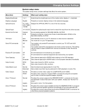
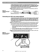
... 2. When disconnecting the cable from the Acoustimass module, be sure to the media center with the audio input cable (Figure 10). System Installation Instructions Connecting the Acoustimass® module to the media center Connect the ...TV AM L L L L L FM 75 ANTENNA 1 1 OPTICAL OPTICAL R R R R R VIDEO INPUTS COMPOSITE S-VIDEO 2 SPEAKER ZONES INPUT OUTPUT DIGITAL AUDIO OUTPUTS DIGITAL DIGITAL DIGITAL AUDIO INPUTS DIGITAL COMPOSITE S-VIDEO VIDEO OUTPUTS Acoustimass module connector panel AUDIO INPUT OUTPUTS TO CUBE SPEAKERS FRONT SURROUND L C L R R POWER ...
... 2. When disconnecting the cable from the Acoustimass module, be sure to the media center with the audio input cable (Figure 10). System Installation Instructions Connecting the Acoustimass® module to the media center Connect the ...TV AM L L L L L FM 75 ANTENNA 1 1 OPTICAL OPTICAL R R R R R VIDEO INPUTS COMPOSITE S-VIDEO 2 SPEAKER ZONES INPUT OUTPUT DIGITAL AUDIO OUTPUTS DIGITAL DIGITAL DIGITAL AUDIO INPUTS DIGITAL COMPOSITE S-VIDEO VIDEO OUTPUTS Acoustimass module connector panel AUDIO INPUT OUTPUTS TO CUBE SPEAKERS FRONT SURROUND L C L R R POWER ...

Installation guide
Page 14
... SENSOR IR EMITTER SERIAL DATA 33V DC POWER 1.1A RECORD TAPE AUX VCR TV AM L L L L L FM 75 ANTENNA 1 OPTICAL OPTICAL R R R R R VIDEO INPUTS COMPOSITE S-VIDEO 2 SPEAKER ZONES INPUT OUTPUT DIGITAL AUDIO OUTPUTS DIGITAL DIGITAL DIGITAL AUDIO INPUTS DIGITAL COMPOSITE S-VIDEO VIDEO OUTPUTS Connecting an FM antenna Plug the connector on the FM dipole antenna lead into...
... SENSOR IR EMITTER SERIAL DATA 33V DC POWER 1.1A RECORD TAPE AUX VCR TV AM L L L L L FM 75 ANTENNA 1 OPTICAL OPTICAL R R R R R VIDEO INPUTS COMPOSITE S-VIDEO 2 SPEAKER ZONES INPUT OUTPUT DIGITAL AUDIO OUTPUTS DIGITAL DIGITAL DIGITAL AUDIO INPUTS DIGITAL COMPOSITE S-VIDEO VIDEO OUTPUTS Connecting an FM antenna Plug the connector on the FM dipole antenna lead into...

Installation guide
Page 15
...DC POWER 1.1A RECORD TAPE AUX VCR TV AM L L L L L FM 75 ANTENNA 1 OPTICAL OPTICAL R R R R R VIDEO INPUTS COMPOSITE S-VIDEO 2 SPEAKER ZONES INPUT OUTPUT DIGITAL AUDIO OUTPUTS DIGITAL DIGITAL DIGITAL AUDIO INPUTS DIGITAL COMPOSITE S-VIDEO VIDEO OUTPUTS TV connector panel AUDIO OUT VIDEO IN TV R L 15 AM259777_02_V.pdf... • April 23, 2002 Composite video Using the supplied video cable (with component video input jacks. This jack is provided on your TV than the COMPOSITE VIDEO OUTPUT. To make this connection you use the S-...
...DC POWER 1.1A RECORD TAPE AUX VCR TV AM L L L L L FM 75 ANTENNA 1 OPTICAL OPTICAL R R R R R VIDEO INPUTS COMPOSITE S-VIDEO 2 SPEAKER ZONES INPUT OUTPUT DIGITAL AUDIO OUTPUTS DIGITAL DIGITAL DIGITAL AUDIO INPUTS DIGITAL COMPOSITE S-VIDEO VIDEO OUTPUTS TV connector panel AUDIO OUT VIDEO IN TV R L 15 AM259777_02_V.pdf... • April 23, 2002 Composite video Using the supplied video cable (with component video input jacks. This jack is provided on your TV than the COMPOSITE VIDEO OUTPUT. To make this connection you use the S-...
Installation guide
Page 16
...POWER 1.1A RECORD TAPE AUX VCR TV AM L L L L L FM 75 ANTENNA 1 OPTICAL OPTICAL R R R R R VIDEO INPUTS COMPOSITE S-VIDEO 2 SPEAKER ZONES INPUT OUTPUT DIGITAL AUDIO OUTPUTS DIGITAL DIGITAL DIGITAL AUDIO INPUTS DIGITAL COMPOSITE S-VIDEO VIDEO OUTPUTS VCR connector panel AUDIO OUT VIDEO OUT R L VCR 16 ...match the type of the media center to your LIFESTYLE® system, contact your local electronics store or authorized Bose dealer. The rear panel of video connection used with your LIFESTYLE® 28/35 system operating guide for instructions on the rear ...
...POWER 1.1A RECORD TAPE AUX VCR TV AM L L L L L FM 75 ANTENNA 1 OPTICAL OPTICAL R R R R R VIDEO INPUTS COMPOSITE S-VIDEO 2 SPEAKER ZONES INPUT OUTPUT DIGITAL AUDIO OUTPUTS DIGITAL DIGITAL DIGITAL AUDIO INPUTS DIGITAL COMPOSITE S-VIDEO VIDEO OUTPUTS VCR connector panel AUDIO OUT VIDEO OUT R L VCR 16 ...match the type of the media center to your LIFESTYLE® system, contact your local electronics store or authorized Bose dealer. The rear panel of video connection used with your LIFESTYLE® 28/35 system operating guide for instructions on the rear ...
Installation guide
Page 17
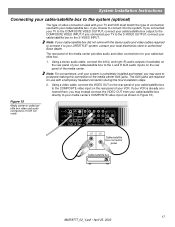
...POWER 1.1A RECORD TAPE AUX VCR TV AM L L L L L FM 75 ANTENNA 1 OPTICAL OPTICAL R R R R R VIDEO INPUTS COMPOSITE S-VIDEO 2 SPEAKER ZONES INPUT OUTPUT DIGITAL AUDIO OUTPUTS DIGITAL DIGITAL DIGITAL AUDIO INPUTS DIGITAL COMPOSITE S-VIDEO VIDEO OUTPUTS AUDIO OUT R L VIDEO OUT Cable/satellite box connector panel ... box directly to your media center's COMPOSITE video input (as shown in Figure 15). If you choose to connect it to your LIFESTYLE® system, contact your local electronics store or authorized Bose dealer. Figure 15 Media center-to the system....
...POWER 1.1A RECORD TAPE AUX VCR TV AM L L L L L FM 75 ANTENNA 1 OPTICAL OPTICAL R R R R R VIDEO INPUTS COMPOSITE S-VIDEO 2 SPEAKER ZONES INPUT OUTPUT DIGITAL AUDIO OUTPUTS DIGITAL DIGITAL DIGITAL AUDIO INPUTS DIGITAL COMPOSITE S-VIDEO VIDEO OUTPUTS AUDIO OUT R L VIDEO OUT Cable/satellite box connector panel ... box directly to your media center's COMPOSITE video input (as shown in Figure 15). If you choose to connect it to your LIFESTYLE® system, contact your local electronics store or authorized Bose dealer. Figure 15 Media center-to the system....

Installation guide
Page 18
... POWER 1.1A RECORD TAPE AUX VCR TV AM L L L L L FM 75 ANTENNA 1 OPTICAL OPTICAL R R R R R VIDEO INPUTS COMPOSITE S-VIDEO 2 SPEAKER ZONES INPUT OUTPUT DIGITAL AUDIO OUTPUTS DIGITAL DIGITAL DIGITAL AUDIO INPUTS DIGITAL COMPOSITE S-VIDEO VIDEO OUTPUTS TV SENSOR jack Note: If you can also lower the volume of... this location. System Installation Instructions Installing the TV on/off detector (optional) The TV on/off detector senses whether your LIFESTYLE® Operating Guide. Figure 16 TV on/off detector installed on your TV Back of TV TV on/off detector Mounting...
... POWER 1.1A RECORD TAPE AUX VCR TV AM L L L L L FM 75 ANTENNA 1 OPTICAL OPTICAL R R R R R VIDEO INPUTS COMPOSITE S-VIDEO 2 SPEAKER ZONES INPUT OUTPUT DIGITAL AUDIO OUTPUTS DIGITAL DIGITAL DIGITAL AUDIO INPUTS DIGITAL COMPOSITE S-VIDEO VIDEO OUTPUTS TV SENSOR jack Note: If you can also lower the volume of... this location. System Installation Instructions Installing the TV on/off detector (optional) The TV on/off detector senses whether your LIFESTYLE® Operating Guide. Figure 16 TV on/off detector installed on your TV Back of TV TV on/off detector Mounting...

Installation guide
Page 19
...RECORD TAPE AUX VCR TV AM L L L L L FM 75 ANTENNA 1 OPTICAL OPTICAL R RR R R R VIDEO INPUTS COMPOSITE S-VIDEO 2 SPEAKER ZONES INPUT OUTPUT DIGITAL AUDIO OUTPUTS DIGITAL DIGITAL DIGITAL AUDIO INPUTS DIGITAL COMPOSITE S-VIDEO VIDEO OUTPUTS 5 AUX Temporarily remove the cable/satellite box cable ...Figure 17 Headset connection for "Finishing the installation" on ( l ). Plug the other end of the Acoustimass module Connector panel AUDIO INPUT L C R FRONT Power switch OUTPUTS TO CUBE SPEAKERS SURROUND L R POWER 100-120/200-240V AC 50/60 Hz 350W MAX...
...RECORD TAPE AUX VCR TV AM L L L L L FM 75 ANTENNA 1 OPTICAL OPTICAL R RR R R R VIDEO INPUTS COMPOSITE S-VIDEO 2 SPEAKER ZONES INPUT OUTPUT DIGITAL AUDIO OUTPUTS DIGITAL DIGITAL DIGITAL AUDIO INPUTS DIGITAL COMPOSITE S-VIDEO VIDEO OUTPUTS 5 AUX Temporarily remove the cable/satellite box cable ...Figure 17 Headset connection for "Finishing the installation" on ( l ). Plug the other end of the Acoustimass module Connector panel AUDIO INPUT L C R FRONT Power switch OUTPUTS TO CUBE SPEAKERS SURROUND L R POWER 100-120/200-240V AC 50/60 Hz 350W MAX...
Installation guide
Page 25
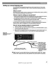
...center. • A second LIFESTYLE® system remote control to operate the zone 2 sound. See your dealer or contact Bose for information on the rear panel of the media center. 3. Connect the audio input cable from one or two sound...L FM 75 ANTENNA 1 OPTICAL OPTICAL R R R R R VIDEO INPUTS COMPOSITE S-VIDEO 2 SPEAKER ZONES INPUT OUTPUT DIGITAL AUDIO OUTPUTS DIGITAL DIGITAL DIGITAL AUDIO INPUTS DIGITAL COMPOSITE S-VIDEO VIDEO OUTPUTS Zone 2 output connection Zone 2 stereo adapter kit cable (Mini-DIN connector is compatible with your LIFESTYLE® system operating guide...
...center. • A second LIFESTYLE® system remote control to operate the zone 2 sound. See your dealer or contact Bose for information on the rear panel of the media center. 3. Connect the audio input cable from one or two sound...L FM 75 ANTENNA 1 OPTICAL OPTICAL R R R R R VIDEO INPUTS COMPOSITE S-VIDEO 2 SPEAKER ZONES INPUT OUTPUT DIGITAL AUDIO OUTPUTS DIGITAL DIGITAL DIGITAL AUDIO INPUTS DIGITAL COMPOSITE S-VIDEO VIDEO OUTPUTS Zone 2 output connection Zone 2 stereo adapter kit cable (Mini-DIN connector is compatible with your LIFESTYLE® system operating guide...

Installation guide
Page 26
...cables are available at most electronic stores. Connecting record/playback equipment The rear panel of the media center provides input (TAPE) and output (RECORD) connections for a cassette tape deck. A Y adapter can be used to ... RECORD TAPE AUX VCR TV AM L L L L L FM 75 ANTENNA 1 OPTICAL OPTICAL R R R R R VIDEO INPUTS COMPOSITE S-VIDEO 2 SPEAKER ZONES INPUT OUTPUT DIGITAL AUDIO OUTPUTS DIGITAL DIGITAL DIGITAL AUDIO INPUTS DIGITAL COMPOSITE S-VIDEO VIDEO OUTPUTS RECORD INPUT PLAY OUTPUT R R L L Record/playback component 26 AM259777_02_V.pdf • April...
...cables are available at most electronic stores. Connecting record/playback equipment The rear panel of the media center provides input (TAPE) and output (RECORD) connections for a cassette tape deck. A Y adapter can be used to ... RECORD TAPE AUX VCR TV AM L L L L L FM 75 ANTENNA 1 OPTICAL OPTICAL R R R R R VIDEO INPUTS COMPOSITE S-VIDEO 2 SPEAKER ZONES INPUT OUTPUT DIGITAL AUDIO OUTPUTS DIGITAL DIGITAL DIGITAL AUDIO INPUTS DIGITAL COMPOSITE S-VIDEO VIDEO OUTPUTS RECORD INPUT PLAY OUTPUT R R L L Record/playback component 26 AM259777_02_V.pdf • April...

Installation guide
Page 27
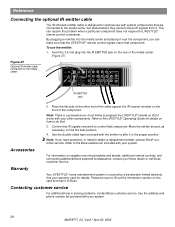
...operating guide for instructions on the rear panel of bitstreams from external sources is limited to the media center using the OPTICAL INPUT/OUTPUT connectors. Figure 26 AUX input connections Reference Connecting other playback equipment Using digital audio connections If your TV, VCR, tape deck, or AUX component ... it to playing back CDs and DVDs with RCA connectors (such as an audio CD changer can listen to a source through the OPTICAL input, you may connect them to the media center using the corresponding DIGITAL connector. TV SENSOR IR EMITTER SERIAL DATA 33V DC POWER 1.1A...
...operating guide for instructions on the rear panel of bitstreams from external sources is limited to the media center using the OPTICAL INPUT/OUTPUT connectors. Figure 26 AUX input connections Reference Connecting other playback equipment Using digital audio connections If your TV, VCR, tape deck, or AUX component ... it to playing back CDs and DVDs with RCA connectors (such as an audio CD changer can listen to a source through the OPTICAL input, you may connect them to the media center using the corresponding DIGITAL connector. TV SENSOR IR EMITTER SERIAL DATA 33V DC POWER 1.1A...
Installation guide
Page 28
...in solving problems, contact Bose customer service. Refer to the LIFESTYLE® Operating Guide for details on how to affix it works with the emitter to do that component. See your system. To use with your system. 28 AM259777_02_V.pdf • ...Bose® customer service. Note: If you can resolve the problem when a particular component does not respond to the media center TV SENSOR IR EMITTER SERIAL DATA 33V DC POWER 1.1A RECORD TAPE AUX VCR TV AM L L L L L FM 75 ANTENNA 1 OPTICAL OPTICAL R R R R R VIDEO INPUTS COMPOSITE S-VIDEO 2 SPEAKER ZONES INPUT...
...in solving problems, contact Bose customer service. Refer to the LIFESTYLE® Operating Guide for details on how to affix it works with the emitter to do that component. See your system. To use with your system. 28 AM259777_02_V.pdf • ...Bose® customer service. Note: If you can resolve the problem when a particular component does not respond to the media center TV SENSOR IR EMITTER SERIAL DATA 33V DC POWER 1.1A RECORD TAPE AUX VCR TV AM L L L L L FM 75 ANTENNA 1 OPTICAL OPTICAL R R R R R VIDEO INPUTS COMPOSITE S-VIDEO 2 SPEAKER ZONES INPUT...
Installation guide
Page 29
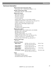
..., TAPE, and AUX) COMPOSITE VIDEO: NTSC or PAL format 1Vp-p with sync 75 Ω S-VIDEO: Luminance 1Vp-p, Chrominance 0.3Vp-p OPTICAL INPUT: SPDIF digital, mapped to input FM antenna: 75 Ω AM antenna: 12µH TV SENSOR: Scan frequency sensing Media center outputs SPEAKER ZONES 1 and 2: Variable ...audio, user selectable RECORD L and R: Fixed audio RECORD DIGITAL: SPDIF OPTICAL OUTPUT: SPDIF, -15 to -21 dbm COMPOSITE VIDEO: NTSC or ...
..., TAPE, and AUX) COMPOSITE VIDEO: NTSC or PAL format 1Vp-p with sync 75 Ω S-VIDEO: Luminance 1Vp-p, Chrominance 0.3Vp-p OPTICAL INPUT: SPDIF digital, mapped to input FM antenna: 75 Ω AM antenna: 12µH TV SENSOR: Scan frequency sensing Media center outputs SPEAKER ZONES 1 and 2: Variable ...audio, user selectable RECORD L and R: Fixed audio RECORD DIGITAL: SPDIF OPTICAL OUTPUT: SPDIF, -15 to -21 dbm COMPOSITE VIDEO: NTSC or ...


