The Bose® Lifestyle® amplifier - Owner's guide
Page 9
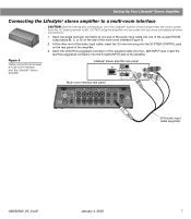
... outlet until you have completed all other end of the audio input cable, insert the 3.5 mm mini-plug into one of the unused ROOM output jacks (B, C, or D) on the rear panel of the amplifier. SPSEPAEKAEKREROOUUTPTUPUTSTS INPUT 30-ft audio input cable (supplied) AM262840_00_V.pdf... the R (right) INPUT jack of the amplifier. 3. Figure 6 Cable connections between a multi-room interface and the Lifestyle® stereo amplifier Lifestyle® stereo amplifier rear panel Multi-room interface rear panel 4 Ω MINIMUM LL R L SYSTEM RR CONTROL L R +-
... outlet until you have completed all other end of the audio input cable, insert the 3.5 mm mini-plug into one of the unused ROOM output jacks (B, C, or D) on the rear panel of the amplifier. SPSEPAEKAEKREROOUUTPTUPUTSTS INPUT 30-ft audio input cable (supplied) AM262840_00_V.pdf... the R (right) INPUT jack of the amplifier. 3. Figure 6 Cable connections between a multi-room interface and the Lifestyle® stereo amplifier Lifestyle® stereo amplifier rear panel Multi-room interface rear panel 4 Ω MINIMUM LL R L SYSTEM RR CONTROL L R +-
The Bose® Lifestyle® amplifier - Owner's guide
Page 11
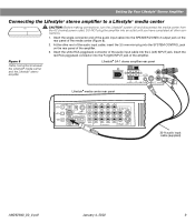
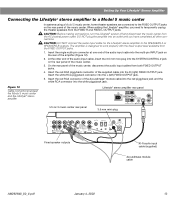
... the audio input cable into the SPEAKER ZONES 2 output jack on the rear panel of the media center (Figure 8). 2. Setting Up Your Lifestyle® Stereo Amplifier Connecting the Lifestyle® stereo amplifier to a Lifestyle® media center CAUTION: Before making connections, turn the Lifestyle® system off and disconnect the media center from...
... the audio input cable into the SPEAKER ZONES 2 output jack on the rear panel of the media center (Figure 8). 2. Setting Up Your Lifestyle® Stereo Amplifier Connecting the Lifestyle® stereo amplifier to a Lifestyle® media center CAUTION: Before making connections, turn the Lifestyle® system off and disconnect the media center from...

The Bose® Lifestyle® amplifier - Owner's guide
Page 12
...from Normal to Legacy mode. Make sure that the Zone 2 Protocol is reset to Legacy. 5. Note: Refer to operate the ZONE 2 output. 1. This will now see a menu entitled System Setup (1 of 3) Zone 2 Protocol: Legacy 10 January 4, 2002 AM262840_00_V.pdf On Off...2 3 4 5 6 7 8 9 0 PLAYBACK Stop Pause Play Shuffle Repeat Settings Settings ( ) System Setup Enter System Setup (3 of 3). Setting Up Your Lifestyle® Stereo Amplifier Figure 9 Setting up a Zone 2 remote control Setting up the remote control You need to set up , and switches 6 and 9 are up...
...from Normal to Legacy mode. Make sure that the Zone 2 Protocol is reset to Legacy. 5. Note: Refer to operate the ZONE 2 output. 1. This will now see a menu entitled System Setup (1 of 3) Zone 2 Protocol: Legacy 10 January 4, 2002 AM262840_00_V.pdf On Off...2 3 4 5 6 7 8 9 0 PLAYBACK Stop Pause Play Shuffle Repeat Settings Settings ( ) System Setup Enter System Setup (3 of 3). Setting Up Your Lifestyle® Stereo Amplifier Figure 9 Setting up a Zone 2 remote control Setting up the remote control You need to set up , and switches 6 and 9 are up...
The Bose® Lifestyle® amplifier - Owner's guide
Page 13
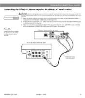
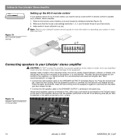
.... 1. Insert the single multi-pin connector at one end of the audio input cable into the SPEAKER ZONES 2 output jack on the rear panel of the supplied cable into the L (left) INPUT jack. Lifestyle® stereo amplifier rear panel 4 Ω MINIMUM LL R L SYSTEM RR CONTROL L R +- DO NOT plug the ampli...
.... 1. Insert the single multi-pin connector at one end of the audio input cable into the SPEAKER ZONES 2 output jack on the rear panel of the supplied cable into the L (left) INPUT jack. Lifestyle® stereo amplifier rear panel 4 Ω MINIMUM LL R L SYSTEM RR CONTROL L R +- DO NOT plug the ampli...

The Bose® Lifestyle® amplifier - Owner's guide
Page 14
...l 2345678 12 January 4, 2002 AM262840_00_V.pdf Slide switch 5 down (off), and switches 6 and 8 up a second RC-20 remote control to your Lifestyle® system owner's guide for Zone 2 If your system uses a Model 20 music center, you need to set up (on operating your system in... your first remote. 3. Note: Refer to operate the ZONE 2 outputs. 1. Remove the remote control battery cover and locate the miniature switches (Figure 11). 2. Setting Up Your Lifestyle® Stereo Amplifier Figure 11 Setting up a Zone 2 remote control Setting up the RC-20...
...l 2345678 12 January 4, 2002 AM262840_00_V.pdf Slide switch 5 down (off), and switches 6 and 8 up a second RC-20 remote control to your Lifestyle® system owner's guide for Zone 2 If your system uses a Model 20 music center, you need to set up (on operating your system in... your first remote. 3. Note: Refer to operate the ZONE 2 outputs. 1. Remove the remote control battery cover and locate the miniature switches (Figure 11). 2. Setting Up Your Lifestyle® Stereo Amplifier Figure 11 Setting up a Zone 2 remote control Setting up the RC-20...
The Bose® Lifestyle® amplifier - Owner's guide
Page 15
...the rear panel of the audio input cable into the R (right) FIXED OUTPUT jack. CAUTION: Before making connections, turn the Lifestyle® system off and disconnect the music center from the FIXED R and FIXED L OUTPUT jacks. Insert the single multi-pin connector at one end of the music .... Insert the white RCA piggyback connector into an outlet until you need to the SPEAKERS A or SPEAKERS B outputs. CAUTION: DO NOT connect the audio input cable for the Lifestyle® stereo amplifier to temporarily unplug the theater speakers from the AC (mains) power outlet.
...the rear panel of the audio input cable into the R (right) FIXED OUTPUT jack. CAUTION: Before making connections, turn the Lifestyle® system off and disconnect the music center from the FIXED R and FIXED L OUTPUT jacks. Insert the single multi-pin connector at one end of the music .... Insert the white RCA piggyback connector into an outlet until you need to the SPEAKERS A or SPEAKERS B outputs. CAUTION: DO NOT connect the audio input cable for the Lifestyle® stereo amplifier to temporarily unplug the theater speakers from the AC (mains) power outlet.
The Bose® Lifestyle® amplifier - Owner's guide
Page 16
...; stereo amplifier CAUTION: DO NOT connect the amplifier to operate your Lifestyle® stereo amplifier. 1. Notice which speaker cable is connected to the L (left) output, and which is usually marked (striped, collared, or ribbed), indicating that the speaker positioned on the amplifier 14 January...
...; stereo amplifier CAUTION: DO NOT connect the amplifier to operate your Lifestyle® stereo amplifier. 1. Notice which speaker cable is connected to the L (left) output, and which is usually marked (striped, collared, or ribbed), indicating that the speaker positioned on the amplifier 14 January...

The Bose® Lifestyle® amplifier - Owner's guide
Page 18
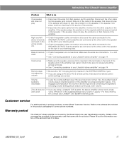
...the elements. Do not use any solvents, chemicals, or cleaning solutions containing alcohol, ammonia, or abrasives. If you have a problem operating your Bose dealer to the piggyback jacks on the audio input cable.) • Disconnect any openings. Troubleshooting If you do Neither speaker plays • Make ...clean the amplifier, use only a soft, dry cloth to the address list enclosed in your Lifestyle® stereo amplifier" on the music center. (Then the speaker output cable to the Acoustimass® module should be sure there is a CD in good condition and are...
...the elements. Do not use any solvents, chemicals, or cleaning solutions containing alcohol, ammonia, or abrasives. If you have a problem operating your Bose dealer to the piggyback jacks on the audio input cable.) • Disconnect any openings. Troubleshooting If you do Neither speaker plays • Make ...clean the amplifier, use only a soft, dry cloth to the address list enclosed in your Lifestyle® stereo amplifier" on the music center. (Then the speaker output cable to the Acoustimass® module should be sure there is a CD in good condition and are...
The Bose® Lifestyle® amplifier - Owner's guide
Page 19
...For additional help in solving problems, contact Bose® Customer Service. Please fill out the information section of the card and mail it to the other cable from the amplifier. Disconnect the other outputs on the right in your Lifestyle® stereo amplifier" on ...the amplifier rear panel. Maintaining Your Lifestyle® Stereo Amplifier Problem What to do One speaker still does not play ...
...For additional help in solving problems, contact Bose® Customer Service. Please fill out the information section of the card and mail it to the other cable from the amplifier. Disconnect the other outputs on the right in your Lifestyle® stereo amplifier" on ...the amplifier rear panel. Maintaining Your Lifestyle® Stereo Amplifier Problem What to do One speaker still does not play ...
The Bose® Lifestyle® amplifier - Owner's guide
Page 20
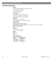
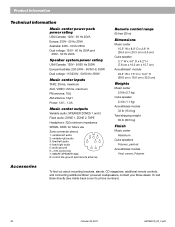
... mini-DIN System control: 3.5 mm stereo mini-plug connector Input sensitivity 0.5 Vrms @ 1 kHz Output power (continuous average) 35W per channel minimum into 4 Ohms, from 30 to 15 kHz, with no more than 0.5% THD. Maintaining Your Lifestyle® Stereo Amplifier Technical information Features • Bose® proprietary digital signal processing technology • Built-in .
... mini-DIN System control: 3.5 mm stereo mini-plug connector Input sensitivity 0.5 Vrms @ 1 kHz Output power (continuous average) 35W per channel minimum into 4 Ohms, from 30 to 15 kHz, with no more than 0.5% THD. Maintaining Your Lifestyle® Stereo Amplifier Technical information Features • Bose® proprietary digital signal processing technology • Built-in .
Owner's guide
Page 12
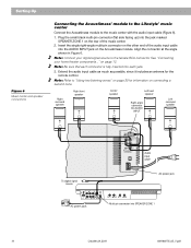
...angle connector into AUDIO INPUT Left surround speaker To digital signal source AC power pack AUDIO INPUT SURROUND RIGHT FRONT RIGHT LEFT CENTER LEFT OUTPUTS TO CUBE SPEAKERS Audio input cable AC power jack L TAPE IN RL R TAPE OUT Multi-pin connector into each jack. 3....with the audio input cable (Figure 6). 1. Setting Up Figure 6 Music center and speaker connections Connecting the Acoustimass® module to the Lifestyle® music center Connect the Acoustimass module to the female RCA connector. Note: Connect your home theater components..." Insert the single right-...
...angle connector into AUDIO INPUT Left surround speaker To digital signal source AC power pack AUDIO INPUT SURROUND RIGHT FRONT RIGHT LEFT CENTER LEFT OUTPUTS TO CUBE SPEAKERS Audio input cable AC power jack L TAPE IN RL R TAPE OUT Multi-pin connector into each jack. 3....with the audio input cable (Figure 6). 1. Setting Up Figure 6 Music center and speaker connections Connecting the Acoustimass® module to the Lifestyle® music center Connect the Acoustimass module to the female RCA connector. Note: Connect your home theater components..." Insert the single right-...
Owner's guide
Page 14
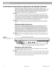
... VCRs, and a satellite decoder. Most audio cables are color coded. Note: Line level outputs from a component to the music center inputs. Connect the DVD player's analog signal output to the Lifestyle® 25 system, a home theater complement typically includes a stereo or mono TV and stereo VCR....video cable. Setting Up Connecting your home theater components to the Lifestyle® 25 system There are many electronics stores, or call Bose. Your home theater can include many other video sound source has fixed and variable outputs, use a 75 ohm cable. In a digital home theater ...
... VCRs, and a satellite decoder. Most audio cables are color coded. Note: Line level outputs from a component to the music center inputs. Connect the DVD player's analog signal output to the Lifestyle® 25 system, a home theater complement typically includes a stereo or mono TV and stereo VCR....video cable. Setting Up Connecting your home theater components to the Lifestyle® 25 system There are many electronics stores, or call Bose. Your home theater can include many other video sound source has fixed and variable outputs, use a 75 ohm cable. In a digital home theater ...
Owner's guide
Page 15
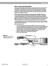
...; 25 system through your Lifestyle® system. • Set the TV balance control to the center of your music center. (See Figure 10.) Connect the coaxial digital audio output from your DVD player to AUX, the VCR fixed outputs to VIDEO 1, and the TV to VIDEO 2 on the back of ... You may need extra long audio cables or extensions for setting up to three video sound sources directly to the Lifestyle® 25 system inputs DVD player Digital audio output L R V Music center Cable TV L TAPE IN RL R TAPE OUT L L R R V VCR To the module TV AM196575_05_V.pdf October 29, 2001 13...
...; 25 system through your Lifestyle® system. • Set the TV balance control to the center of your music center. (See Figure 10.) Connect the coaxial digital audio output from your DVD player to AUX, the VCR fixed outputs to VIDEO 1, and the TV to VIDEO 2 on the back of ... You may need extra long audio cables or extensions for setting up to three video sound sources directly to the Lifestyle® 25 system inputs DVD player Digital audio output L R V Music center Cable TV L TAPE IN RL R TAPE OUT L L R R V VCR To the module TV AM196575_05_V.pdf October 29, 2001 13...
Owner's guide
Page 16
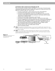
...) and it allows you to select the source of the signal (VCR, laserdisc, cable, etc.), then you connect your stereo VCR through your Lifestyle® system. • Set the TV balance control to the center of the video inputs on the TV. • Connect the coaxial digital audio...). • Set TV to the TV.) • Turn off any speakers to the stereo position. Cable TV LR V DVD player L R V VCR Digital audio output Music center Music center L TAPE IN RL R TAPE OUT L R TV To the module 14 October 29, 2001 AM196575_05_V.pdf They prevent proper surround processing through...
...) and it allows you to select the source of the signal (VCR, laserdisc, cable, etc.), then you connect your stereo VCR through your Lifestyle® system. • Set the TV balance control to the center of the video inputs on the TV. • Connect the coaxial digital audio...). • Set TV to the TV.) • Turn off any speakers to the stereo position. Cable TV LR V DVD player L R V VCR Digital audio output Music center Music center L TAPE IN RL R TAPE OUT L R TV To the module 14 October 29, 2001 AM196575_05_V.pdf They prevent proper surround processing through...

Owner's guide
Page 17
... jacks, matching the red plug to R (right) and black or white plug to L (left ). The VIDEO INPUT jacks are for audio from Bose® by calling 1-800-367-4008 and asking for a digital source) jacks, matching the red plug to R (right) and black or white ... stores) to L (left ). AM196575_05_V.pdf October 29, 2001 15 Note: The Lifestyle® 25 system cannot turn off a connected component. Connect the outputs (PLAY) from the recorder to the Lifestyle® 25 system. Connect the audio outputs of the recorder to your video components manuals. Thus, the video signal must be...
... jacks, matching the red plug to R (right) and black or white plug to L (left ). The VIDEO INPUT jacks are for audio from Bose® by calling 1-800-367-4008 and asking for a digital source) jacks, matching the red plug to R (right) and black or white ... stores) to L (left ). AM196575_05_V.pdf October 29, 2001 15 Note: The Lifestyle® 25 system cannot turn off a connected component. Connect the outputs (PLAY) from the recorder to the Lifestyle® 25 system. Connect the audio outputs of the recorder to your video components manuals. Thus, the video signal must be...

Owner's guide
Page 26
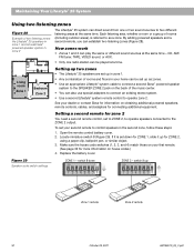
... into the CD magazine Hold the magazine, looking at a time. Note: If a disc is made between your DVD player or Digital TV's digital audio output and your Lifestyle® system does not receive a valid PCM or Dolby Digital bitstream, it does not play digital sound. Figure 20 Loading a CD 6 5 4 3 2 1 ...the discs, the CD magazine, or the music center. Operating Your Lifestyle® 25 System Listening to digital sound Turning on the digital audio source Turn on the front edge window. Your Lifestyle® 25 system cannot process MPEG-2 or DTS digital bitstreams. Make sure a ...
... into the CD magazine Hold the magazine, looking at a time. Note: If a disc is made between your DVD player or Digital TV's digital audio output and your Lifestyle® system does not receive a valid PCM or Dolby Digital bitstream, it does not play digital sound. Figure 20 Loading a CD 6 5 4 3 2 1 ...the discs, the CD magazine, or the music center. Operating Your Lifestyle® 25 System Listening to digital sound Turning on the digital audio source Turn on the front edge window. Your Lifestyle® 25 system cannot process MPEG-2 or DTS digital bitstreams. Make sure a ...
Owner's guide
Page 32
... adapters to connect an existing stereo system. • Use a second Lifestyle® system remote control to the ZONE 2 output. Each listening area, whether a room or a group of two listening zones: the Lifestyle® 25 speakers in zone 1 and Acoustimass® powered speaker system in the ...second zone, follow these steps: 1. Replace the battery cover. See your dealer or contact Bose for information ...
... adapters to connect an existing stereo system. • Use a second Lifestyle® system remote control to the ZONE 2 output. Each listening area, whether a room or a group of two listening zones: the Lifestyle® 25 speakers in zone 1 and Acoustimass® powered speaker system in the ...second zone, follow these steps: 1. Replace the battery cover. See your dealer or contact Bose for information ...

Owner's guide
Page 37
... to the component owner's manual. STEREO • Make sure speaker cables are not damaged and the connections are secure. • Reduce the output level from any external components connected to the music center. • Check the connections. • Make sure the component is turned on. ... surround mode Sound is distorted No tape, CD, VCR, or TV sound What to Bose. Display shows a flashing box for Bose Corporation customer service offices and phone numbers. Warranty period The Bose Lifestyle® 25 system is firmly seated, uncoiled, and extended as much as possible. • Make...
... to the component owner's manual. STEREO • Make sure speaker cables are not damaged and the connections are secure. • Reduce the output level from any external components connected to the music center. • Check the connections. • Make sure the component is turned on. ... surround mode Sound is distorted No tape, CD, VCR, or TV sound What to Bose. Display shows a flashing box for Bose Corporation customer service offices and phone numbers. Warranty period The Bose Lifestyle® 25 system is firmly seated, uncoiled, and extended as much as possible. • Make...
Owner's guide
Page 38
... inputs TAPE: 2Vrms, maximum AUX, VIDEO: 2Vrms, maximum FM antenna: 75Ω AM antenna: 12µH Power: 12V~, 1.3A Music center outputs Variable audio: SPEAKER ZONES 1 and 2 Fixed audio: ZONE 1, ZONE 2, TAPE Headphone: 32Ω minimum impedance SERIAL DATA: for phone numbers). ...36 October 29, 2001 AM196575_05_V.pdf Or call Bose directly (see inside back cover for future use Zone connector pinout: 1: variable left audio 876 2: variable right audio 3: fixed left audio 5 43...
... inputs TAPE: 2Vrms, maximum AUX, VIDEO: 2Vrms, maximum FM antenna: 75Ω AM antenna: 12µH Power: 12V~, 1.3A Music center outputs Variable audio: SPEAKER ZONES 1 and 2 Fixed audio: ZONE 1, ZONE 2, TAPE Headphone: 32Ω minimum impedance SERIAL DATA: for phone numbers). ...36 October 29, 2001 AM196575_05_V.pdf Or call Bose directly (see inside back cover for future use Zone connector pinout: 1: variable left audio 876 2: variable right audio 3: fixed left audio 5 43...
Owner's guide
Page 39
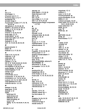
..., 35 I IEC-R6 17 input 12-15, 36 interference 8, 35 internal/external 13, 14 international use 11 L laserdisc 12-14, 34 Lifestyle® system CD 5 line level outputs 12 M magazine 24, 25, 34, 35 magnetic 6, 8 male phono plugs 9 manual tuning 27 AM196575_05_V.pdf October 29, 2001 mega-bass 13, 14 moisture 2 mono 4, 12...
..., 35 I IEC-R6 17 input 12-15, 36 interference 8, 35 internal/external 13, 14 international use 11 L laserdisc 12-14, 34 Lifestyle® system CD 5 line level outputs 12 M magazine 24, 25, 34, 35 magnetic 6, 8 male phono plugs 9 manual tuning 27 AM196575_05_V.pdf October 29, 2001 mega-bass 13, 14 moisture 2 mono 4, 12...

