
Owner's guide
Page 1
The Bose® Acoustimass® 15 Home Theater Speaker System Owner's Guide October 22, 2001 AM194452_06_V.pdf
The Bose® Acoustimass® 15 Home Theater Speaker System Owner's Guide October 22, 2001 AM194452_06_V.pdf
Owner's guide
Page 2
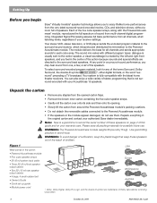
... Integrated Signal Processing and dedicated bass amplification assure hi-fidelity and bass for future reference. 2 October 22, 2001 AM194452_06_V.pdf REFER SERVICING TO QUALIFIED PERSONNEL. Introduction Thank you We appreciate your choice of your home theater receiver's settings. With these Virtually Invisible® speakers you will help you set up and operate your system properly, and enjoy all channels regardless of the Bose® Acoustimass® 15 home theater speaker...
... Integrated Signal Processing and dedicated bass amplification assure hi-fidelity and bass for future reference. 2 October 22, 2001 AM194452_06_V.pdf REFER SERVICING TO QUALIFIED PERSONNEL. Introduction Thank you We appreciate your choice of your home theater receiver's settings. With these Virtually Invisible® speakers you will help you set up and operate your system properly, and enjoy all channels regardless of the Bose® Acoustimass® 15 home theater speaker...
Owner's guide
Page 3
... from the wall outlet before using this equipment has been tested and found to comply with its ventilation openings. 8. This product complies with the apparatus. Do not use this apparatus near any heat sources, such as radiators, heat registers, stoves or other hazards. Clean only with the manufacturer's instructions - To ensure reliable operation of the receiver or radio remote control could result...
... from the wall outlet before using this equipment has been tested and found to comply with its ventilation openings. 8. This product complies with the apparatus. Do not use this apparatus near any heat sources, such as radiators, heat registers, stoves or other hazards. Clean only with the manufacturer's instructions - To ensure reliable operation of the receiver or radio remote control could result...

Owner's guide
Page 4
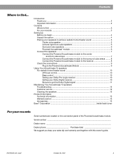
..., be fatal. Use proper power sources - Do not install external antennas near overhead power lines or other electric light or power circuits, nor where an antenna can fall into a proper power source, as described in wire Ground clamp Electric service equipment Antenna discharge unit (NEC Section 810-20) Grounding conductors (NEC Section 810-21) Ground clamps Power service grounding electrode system (NEC ART 250, Part H) Note to...
..., be fatal. Use proper power sources - Do not install external antennas near overhead power lines or other electric light or power circuits, nor where an antenna can fall into a proper power source, as described in wire Ground clamp Electric service equipment Antenna discharge unit (NEC Section 810-20) Grounding conductors (NEC Section 810-21) Ground clamps Power service grounding electrode system (NEC ART 250, Part H) Note to...
Owner's guide
Page 5
... the speakers 7 Connect the Powered Acoustimass module to the center and front cube arrays 7 Connect the Powered Acoustimass module to the surround cube arrays ......... 8 Connect the Powered Acoustimass module to the receiver 8 Check the connections 9 Plug in the Powered Acoustimass Module 9 Using Your Acoustimass 15 speakers For realistic home theater sound 10 LFE level control 10 Bass control ...10 Setting your Dolby Pro-Logic receiver 10 Setting your Dolby Digital receiver 10 Be sure to get the Dolby Digital signal 11 Maintaining Your Acoustimass 15 speakers Troubleshooting ...12...
... the speakers 7 Connect the Powered Acoustimass module to the center and front cube arrays 7 Connect the Powered Acoustimass module to the surround cube arrays ......... 8 Connect the Powered Acoustimass module to the receiver 8 Check the connections 9 Plug in the Powered Acoustimass Module 9 Using Your Acoustimass 15 speakers For realistic home theater sound 10 LFE level control 10 Bass control ...10 Setting your Dolby Pro-Logic receiver 10 Setting your Dolby Digital receiver 10 Be sure to get the Dolby Digital signal 11 Maintaining Your Acoustimass 15 speakers Troubleshooting ...12...
Owner's guide
Page 6
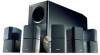
... carton: • Powered Acoustimass module • Five cube speaker arrays • 20' (6 m) system input cable • Three 20' (6 m) front speaker output cables • Two 50' (15 m) rear speaker output cables • 4 large, 4 small rubber feet • Owner's Guide • Quick set up guide • Module power cord USA Europe UK/Singapore Australia * Dolby, Dolby Digital, Dolby Pro-Logic, and the double-D symbol are directed to the surround (rear) speakers. To select surround-encoded program material, look for possible future use them. Your...
... carton: • Powered Acoustimass module • Five cube speaker arrays • 20' (6 m) system input cable • Three 20' (6 m) front speaker output cables • Two 50' (15 m) rear speaker output cables • 4 large, 4 small rubber feet • Owner's Guide • Quick set up guide • Module power cord USA Europe UK/Singapore Australia * Dolby, Dolby Digital, Dolby Pro-Logic, and the double-D symbol are directed to the surround (rear) speakers. To select surround-encoded program material, look for possible future use them. Your...
Owner's guide
Page 7
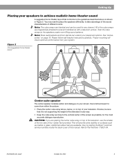
..., for Part Number 178321-04. Figure 2 One suggested home theater layout that it is shown in any channel. Ask for the most accurate dialogue reproduction. You may want to place the speakers differently, to take advantage of the sound characteristics of the screen as marble or glass. Setting Up Placing your speakers to achieve realistic home theater sound A suggested home theater layout Center cube speaker The center speaker localizes...
..., for Part Number 178321-04. Figure 2 One suggested home theater layout that it is shown in any channel. Ask for the most accurate dialogue reproduction. You may want to place the speakers differently, to take advantage of the sound characteristics of the screen as marble or glass. Setting Up Placing your speakers to achieve realistic home theater sound A suggested home theater layout Center cube speaker The center speaker localizes...

Owner's guide
Page 8
..., if possible • Adjust the rear surround speakers to direct the sound to the bottom surface for the module, attach the larger set of four rubber feet to the front and back of sight. CAUTION: To prevent interference, keep the module at least 6 feet (2 m), or as much as 15 feet (5 m) apart. Powered Acoustimass® module Bose® Acoustimass speaker technology takes advantage of...
..., if possible • Adjust the rear surround speakers to direct the sound to the bottom surface for the module, attach the larger set of four rubber feet to the front and back of sight. CAUTION: To prevent interference, keep the module at least 6 feet (2 m), or as much as 15 feet (5 m) apart. Powered Acoustimass® module Bose® Acoustimass speaker technology takes advantage of...

Owner's guide
Page 9
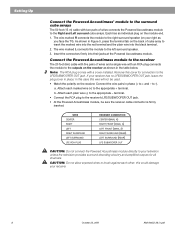
... your receiver. See Figure 5. Setting Up Connect the speakers Connect the cube arrays to the Powered Acoustimass® module, and then connect the module to a receiver output. CAUTION: Never connect the cubes directly to your system. Connect the Powered Acoustimass module to the center and front cube arrays Three individual 20 (6m) foot wire pairs connect the Powered Acoustimass module to comfortably reach the speakers. The cables may result in -wall installation. The supplied cables make...
... your receiver. See Figure 5. Setting Up Connect the speakers Connect the cube arrays to the Powered Acoustimass® module, and then connect the module to a receiver output. CAUTION: Never connect the cubes directly to your system. Connect the Powered Acoustimass module to the center and front cube arrays Three individual 20 (6m) foot wire pairs connect the Powered Acoustimass module to comfortably reach the speakers. The cables may result in -wall installation. The supplied cables make...
Owner's guide
Page 10
... (15 m) cable with two pairs of wires connects the Powered Acoustimass module to the appropriate + terminal. WIRE CENTER RIGHT LEFT RIGHT SURROUND LEFT SURROUND LFE RCA PLUG RECEIVER CONNECTION CENTER (MAIN, A) RIGHT FRONT (MAIN, A) LEFT FRONT (MAIN, A) RIGHT SURROUND (REAR) LEFT SURROUND (REAR) LFE SUBWOOFER OUT CAUTION: Do not connect the Powered Acoustimass module directly to your television unless the television provides surround decoding circuitry and amplified outputs for connection to the LFE/SUBWOOFER OUT jack. The wire marked R connects the...
... (15 m) cable with two pairs of wires connects the Powered Acoustimass module to the appropriate + terminal. WIRE CENTER RIGHT LEFT RIGHT SURROUND LEFT SURROUND LFE RCA PLUG RECEIVER CONNECTION CENTER (MAIN, A) RIGHT FRONT (MAIN, A) LEFT FRONT (MAIN, A) RIGHT SURROUND (REAR) LEFT SURROUND (REAR) LFE SUBWOOFER OUT CAUTION: Do not connect the Powered Acoustimass module directly to your television unless the television provides surround decoding circuitry and amplified outputs for connection to the LFE/SUBWOOFER OUT jack. The wire marked R connects the...
Owner's guide
Page 11
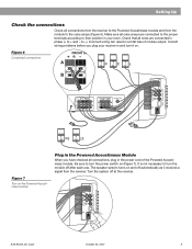
... their position in your receiver in and turn it receives a signal from the module to turn the power switch on . Turn the system off after each use. AM194452_06_V.pdf October 22, 2001 9 Incorrect wiring can result in the power cord of module output. Figure 6 Completed connections FRONT SPEAKE R 3+ RIGHT +3 FRONT SPEAKERS R L SURROUND SPEAKERS R REAR L CENTER LFE/SUBWOOFER OUT Figure 7 Turn on the Powered Acoustimass module Plug in the Powered Acoustimass Module When you plug your room. Be sure...
... their position in your receiver in and turn it receives a signal from the module to turn the power switch on . Turn the system off after each use. AM194452_06_V.pdf October 22, 2001 9 Incorrect wiring can result in the power cord of module output. Figure 6 Completed connections FRONT SPEAKE R 3+ RIGHT +3 FRONT SPEAKERS R L SURROUND SPEAKERS R REAR L CENTER LFE/SUBWOOFER OUT Figure 7 Turn on the Powered Acoustimass module Plug in the Powered Acoustimass Module When you plug your room. Be sure...
Owner's guide
Page 12
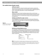
... Dolby Digital receiver Your Acoustimass 15 speakers are fully compatible with the LFE level control, you are full-range, or LARGE speakers on the Digital screen menu. Turning down the control will add bass to regulate the presence of each speaker. The cube speakers are using. Speaker Setting at receiver Left and Right Front Large Center Large Left and Right Surround Large Subwoofer ON LFE (low frequency effects) ON (at maximum setting) Note: The Acoustimass 15 speaker system incorporates an automatic protection...
... Dolby Digital receiver Your Acoustimass 15 speakers are fully compatible with the LFE level control, you are full-range, or LARGE speakers on the Digital screen menu. Turning down the control will add bass to regulate the presence of each speaker. The cube speakers are using. Speaker Setting at receiver Left and Right Front Large Center Large Left and Right Surround Large Subwoofer ON LFE (low frequency effects) ON (at maximum setting) Note: The Acoustimass 15 speaker system incorporates an automatic protection...
Owner's guide
Page 13
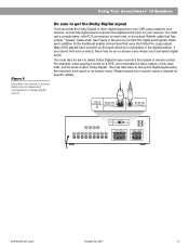
... get the Dolby Digital signal To be an on screen menu where you must use a coaxial cable, with RCA connectors on -screen menu. AC-3 DIGITAL IN PLAY IN (OPTICAL) PLAY IN (COAXIAL) AC-3 DIGITAL IN PLAY IN (OPTICAL) PLAY IN (COAXIAL) FRONT SPEAKERS R L SURROUND SPEAKERS R REAR L CENTER AM194452_06_V.pdf October 22, 2001 11 Using Your Acoustimass® 15 Speakers Figure 9 Use either the optical or coaxial digital sound cables and connections for specific details. You must select a video output, in addition to set up the digital signal using the receiver's front panel or on...
... get the Dolby Digital signal To be an on screen menu where you must use a coaxial cable, with RCA connectors on -screen menu. AC-3 DIGITAL IN PLAY IN (OPTICAL) PLAY IN (COAXIAL) AC-3 DIGITAL IN PLAY IN (OPTICAL) PLAY IN (COAXIAL) FRONT SPEAKERS R L SURROUND SPEAKERS R REAR L CENTER AM194452_06_V.pdf October 22, 2001 11 Using Your Acoustimass® 15 Speakers Figure 9 Use either the optical or coaxial digital sound cables and connections for specific details. You must select a video output, in addition to set up the digital signal using the receiver's front panel or on...

Owner's guide
Page 14
... the audio source selected is turned ON. If you are easily damaged if reasonable care is not damaged. • Reduce the volume of external components connected to the receiver. • Make sure the speaker connections at the receiver or amplifier are correct at the receiver (video, CD, DVD, tuner). • Check the speaker connections. • Turn the Powered Acoustimass module ON. • For digital sound, be sure a coaxial or optical cable connects the digital output of the DVD player with the digital input...
... the audio source selected is turned ON. If you are easily damaged if reasonable care is not damaged. • Reduce the volume of external components connected to the receiver. • Make sure the speaker connections at the receiver or amplifier are correct at the receiver (video, CD, DVD, tuner). • Check the speaker connections. • Turn the Powered Acoustimass module ON. • For digital sound, be sure a coaxial or optical cable connects the digital output of the DVD player with the digital input...
Owner's guide
Page 15
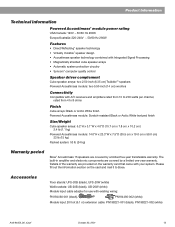
...® computer quality control Speaker driver complement Cube speaker arrays: two 2.50-inch (6.35 cm) TwiddlerTM speakers Powered Acoustimass module: two 5.50-inch (14 cm) woofers Connectivity Compatible with A/V receivers and amplifiers rated from 10 to 200 watts per channel, rated from 4 to Bose. Accessories Floor stands: UFS-20B (black), UFS-20W (white) Wall brackets: UB-20B (black), UB-20W (white) Module input cable adapter for use with your system...
...® computer quality control Speaker driver complement Cube speaker arrays: two 2.50-inch (6.35 cm) TwiddlerTM speakers Powered Acoustimass module: two 5.50-inch (14 cm) woofers Connectivity Compatible with A/V receivers and amplifiers rated from 10 to 200 watts per channel, rated from 4 to Bose. Accessories Floor stands: UFS-20B (black), UFS-20W (white) Wall brackets: UB-20B (black), UB-20W (white) Module input cable adapter for use with your system...
Owner's guide
Page 17
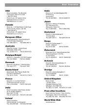
...011) 648 4462 FAX (011) 648 4463 Ireland Bose Corporation Carrickmacross, Co Monaghan TEL (042) 9661988 FAX (042) 9661998 Bose® Corporation Italia Bose S.p.A., Via della Magliana 876 00148 Roma www.bose.iT TEL 06-65670802 FAX 06-65680167 Japan Bose K.K., Shibuya YT Building 28-3 Maruyama-cho Shibuya-ku... 4 S-43153 Mölndal TEL 31-878850 FAX 31-274891 United Kingdom Bose Limited 1 Ambley Green Gillingham Business Park Gillingham, Kent ME8 ONJ TEL 0870-741-4500 FAX 0870-741-4545 From other locations Bose Customer Service, 1 New York Ave. Framingham, MA 01701-9168 USA TEL (508) ...
...011) 648 4462 FAX (011) 648 4463 Ireland Bose Corporation Carrickmacross, Co Monaghan TEL (042) 9661988 FAX (042) 9661998 Bose® Corporation Italia Bose S.p.A., Via della Magliana 876 00148 Roma www.bose.iT TEL 06-65670802 FAX 06-65680167 Japan Bose K.K., Shibuya YT Building 28-3 Maruyama-cho Shibuya-ku... 4 S-43153 Mölndal TEL 31-878850 FAX 31-274891 United Kingdom Bose Limited 1 Ambley Green Gillingham Business Park Gillingham, Kent ME8 ONJ TEL 0870-741-4500 FAX 0870-741-4545 From other locations Bose Customer Service, 1 New York Ave. Framingham, MA 01701-9168 USA TEL (508) ...

Owner's guide
Page 18
© 2000 Bose Corporation, The Mountain, Framingham, MA 01701-9168 USA 194452 AM Rev. 06 JN98831
© 2000 Bose Corporation, The Mountain, Framingham, MA 01701-9168 USA 194452 AM Rev. 06 JN98831


